Under Construction!!!
My Clayton & Lambert Lead Melter
or my
Rocket Stove Restovication
Please Read: Click on the small pics to see full size versions of them then use your back button in your browser to return here...
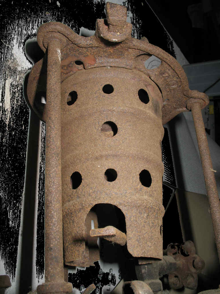
Fig. 1 At the Flea Market |
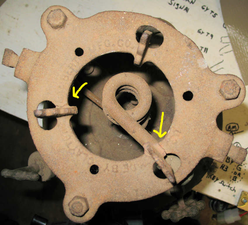
Fig. 2 Top View |
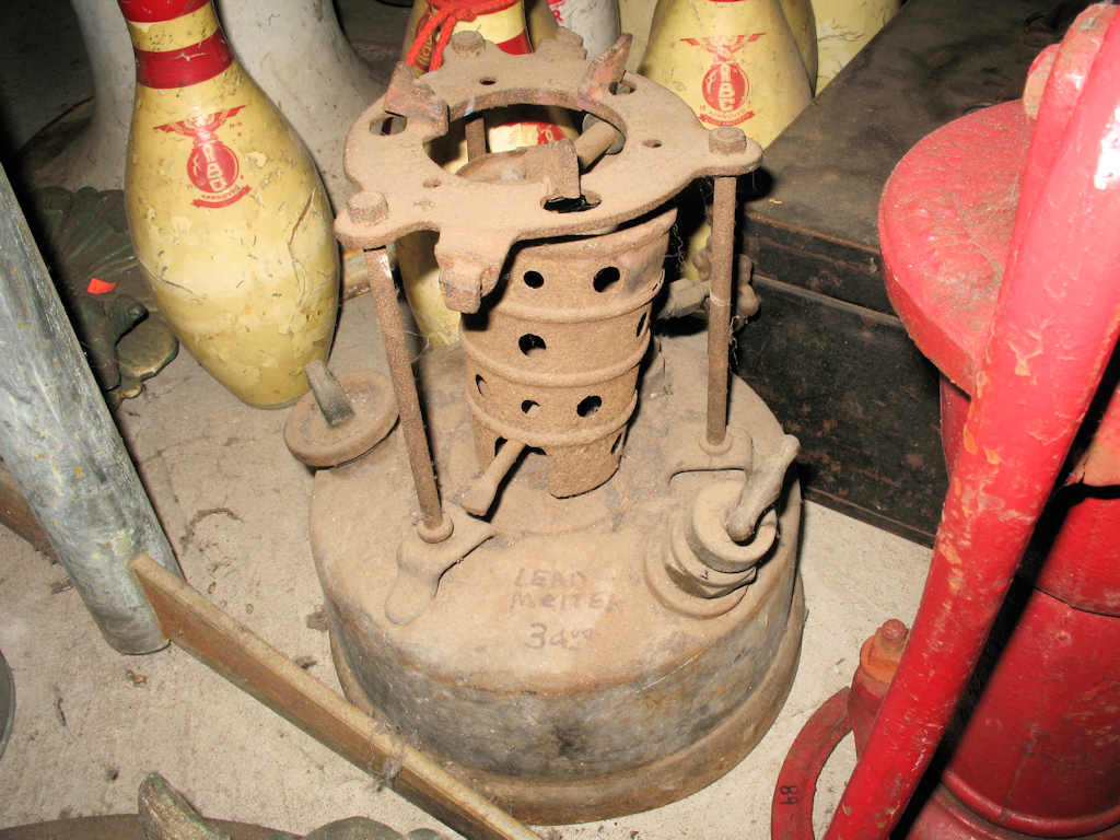
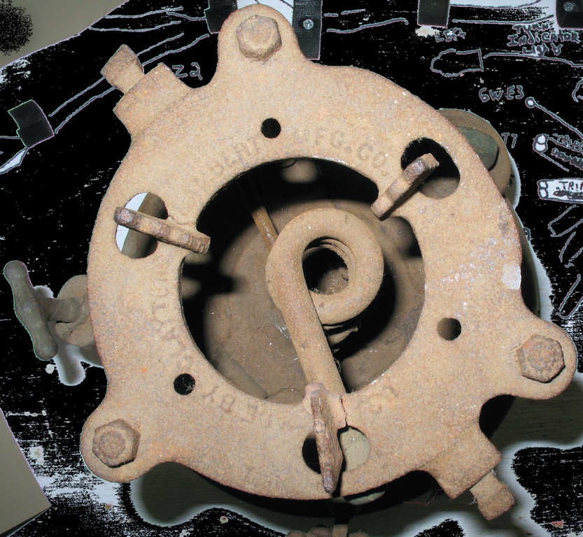
Picked this up for $30 at a flea market. It was a total impulse buy. I didn't even know what it really was! Turns out it's missing the carrying handle, the starter cup, and the melting pot. I now know I overpaid by about $20... Fig. 1 shows the stove as I found it in the store. Fig. 2 is a view looking straight down on the pot holder. You can see the simple vaporizer coil (generator).
So what is it you may ask? This is basically a large gasoline powered blow torch that plumbers used to melt lead for sealing joints in pipes. This one has been well used as indicated by the cracked cast iron pot holder and the flame eroded wind screen.
Evaluating the Stove
Fig. 3 |
Fig. 4 |
Fig. 5 |
Fig. 6 |
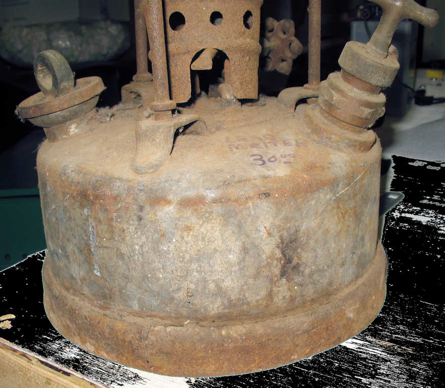
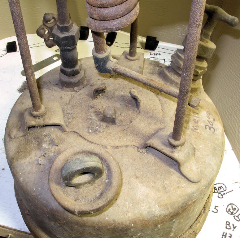
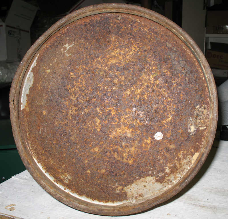
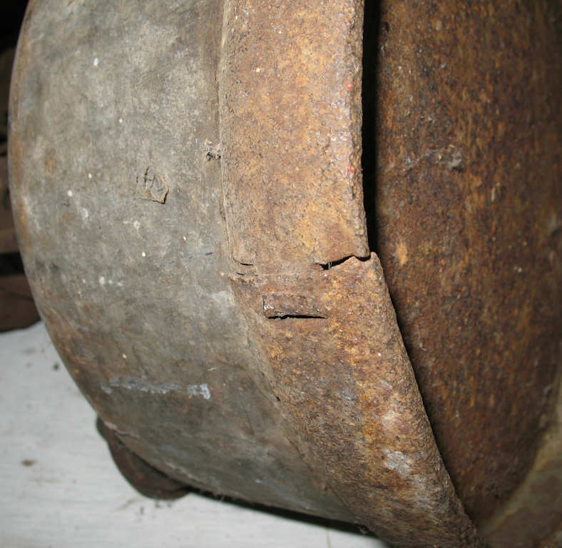
Fig. 3-4 shows how dirty this poor stove was when found. I at first thought this stove was rusted badly from exposure to water, but soon realized that the "rust pitting" on the tops of the pot support legs, pot support, and wind screen were probably "flame erosion" from heavy use? What led me to this conclusion was the fact that the fount itself has little corrosion beyond surface rust. The trim ring shown in Fig. 6 is probably the worst of the rust.
Fig. 7
|
Fig. 8
|
Fig. 9
|
The cast iron pot holder has a couple of heat cracks as shown in Fig. 7. These cracks do not affect the ability to hold a pot full of lead.
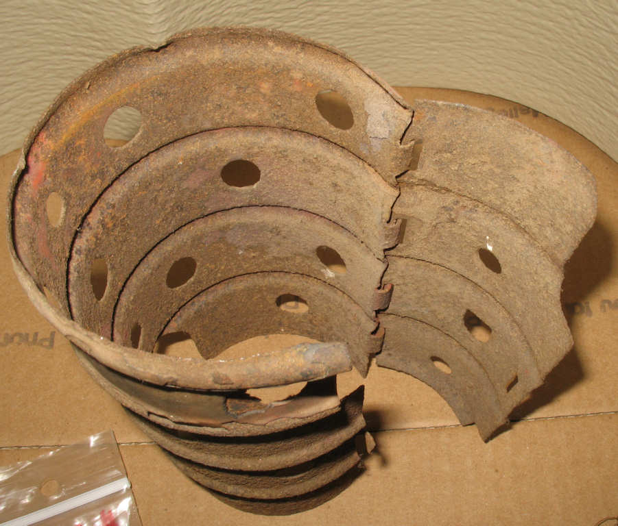
I started this project by removing the wind screen that surrounds the vaporizer coil. See Fig. 8. The top of this screen fits a groove in the bottom of the cast pot holder (See Fig. 9) and sits on top of the pre-heater cup. It has a hinged "door" to allow it to be installed around the coil and latches together when installed. I put it in the de-rust tank and moved on to taking all the plumbing fittings off the tank.
It wasn't until I started taking off the plumbing fittings that I realized that they were solid brass! Those will clean up nice!
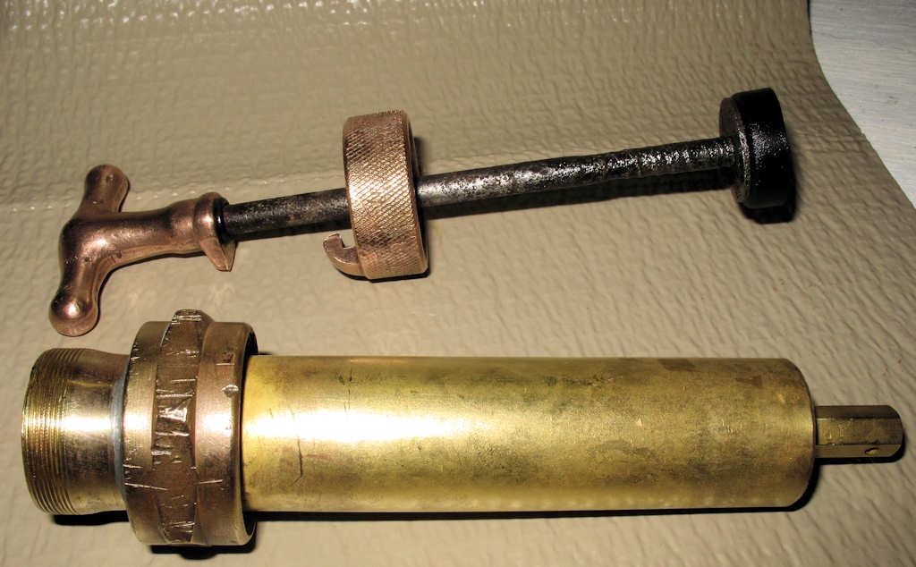
Fig. 10 Pump Assembly |
Fig. 11 Removing Knurled Pump Guide |
Fig. 12 Rusty Pump |
Fig. 13 |
Fig.14 Dried out leather |
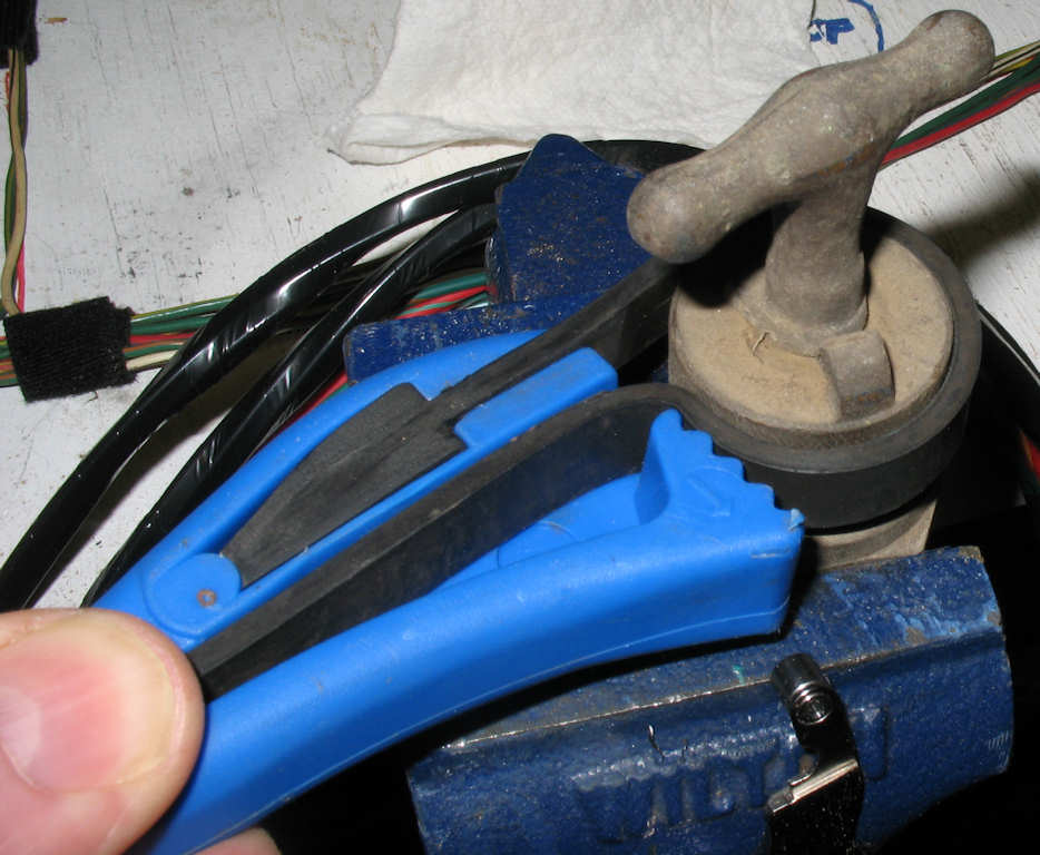
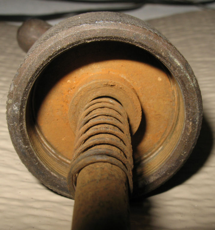
OK so lets take this thing apart. I started by removing the pump assembly. Someone had use a pair of channel locks on it as you can see in Fig. 10. I used a large adjustable wrench and it came right off. I clamped the pump assembly in a small vice and used a small strap wrench to remove the pump guide. Figs. 12-14 show the rusty, and dried out parts of the pump.
Fig. 15 Nice! |
Fig. 16 Clean Pump |
I washed the parts with hot soapy water, placed some of them in warm vinegar and put the pump leather into some light weight oil to soak for a while. After about an hour I pulled them out and went over them with 0000 steel wool. Wow! What a difference! See Fig. 15. Even the inside of the pump was shiny brass... I of course had to try the pump to see if the leather cup worked after years of being dry and it did! I was able to pressurize the tank easily but... I had the dreaded haunted pump handle... (It would rise all by itself after pumping. :-) ) This indicated that the NRV was leaking and needed attention. On to NRV disassembly.
Fig. 17 NRV Assembly |
Fig. 18 Removing |
Fig. 19 Disassembled |
Fig. 20 Pip Placement and Shape |
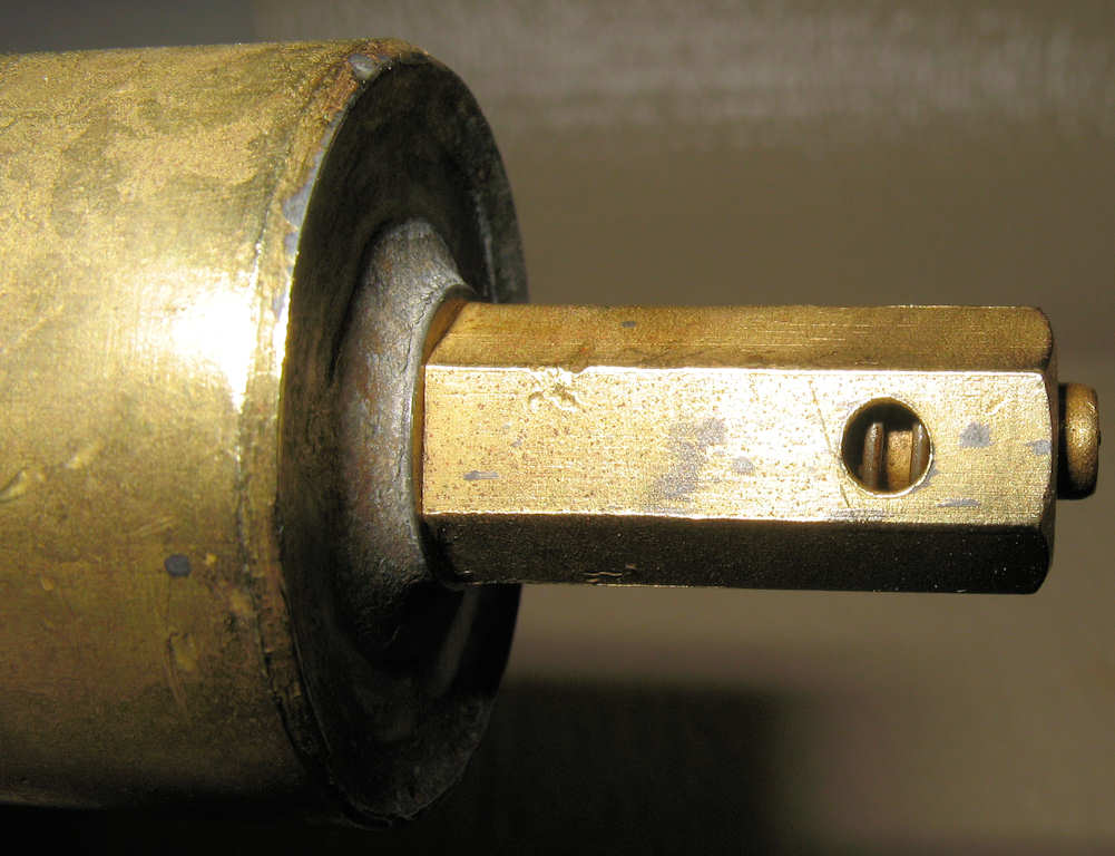
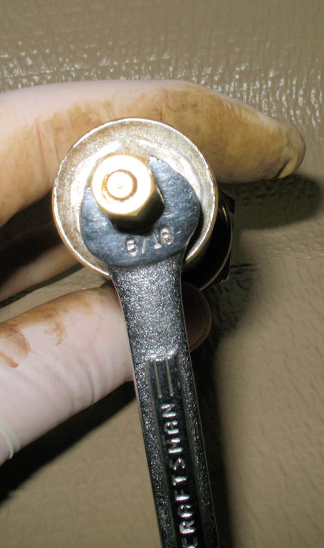
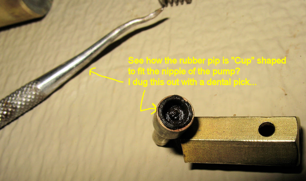
Fig. 17 shows the location of the NRV. A 5/16" wrench is used to remove it, revealing 4 simple pieces (including the rubber pip). See Fig. 19-20. The pip is sort of cup shaped and the nipple of the pump fits into it. My pip was hard, but crumbled easily when poked with a dental pick. I dug it all out, then started looking for a replacement pip. A new friend I made on the stove forum graciously sent me several pips one of which seemed to fit but was NOT cup shaped. It sort of worked but did not completely stop the leak. It just slowed it down. I took it apart again and slightly stretched the spring and tried it again. Still leaking... Grrrr..... I elected to move forward hoping that maybe the pip would "take a set" and finally seal. As of 12/9/2010 it still leaks... I'll find something eventually that is thick and soft enough, and fuel resistant....
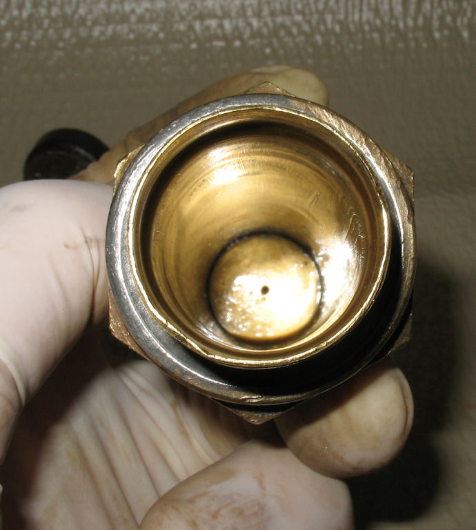
Fig. 21 Before Cleaning |
Fig. 22 Lead Seal |
Fig. 23
|
Fig. 24 After Cleaning |
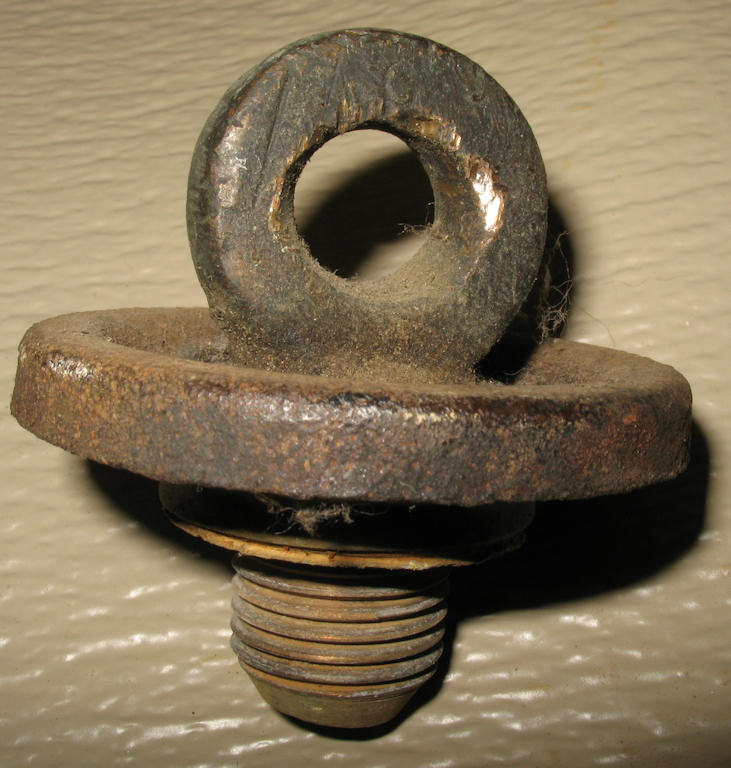
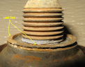
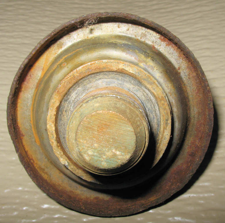
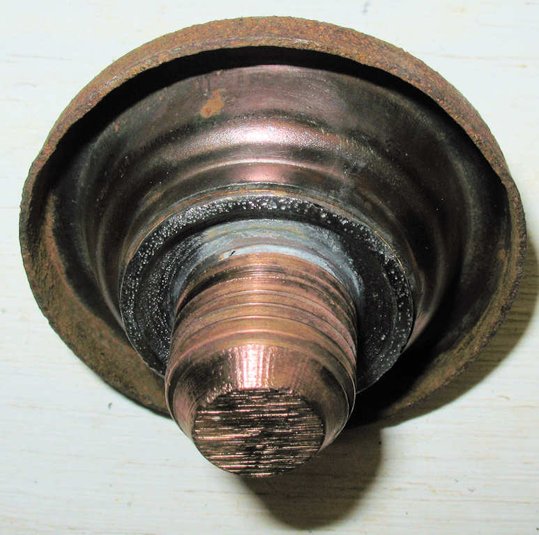
The odd fill cap was next. While cleaning the cap, you will notice the lead seal. See Fig. 23. In order to make a tight seal with the lip of the fill port, this seal must be tightly compressed. In case you were wondering about the super thick washer thingy? It's for putting a screwdriver or other tool into to aid in tightening it up firmly. The cap is part steel and part brass.
Continue to Page #2