Fig. 1
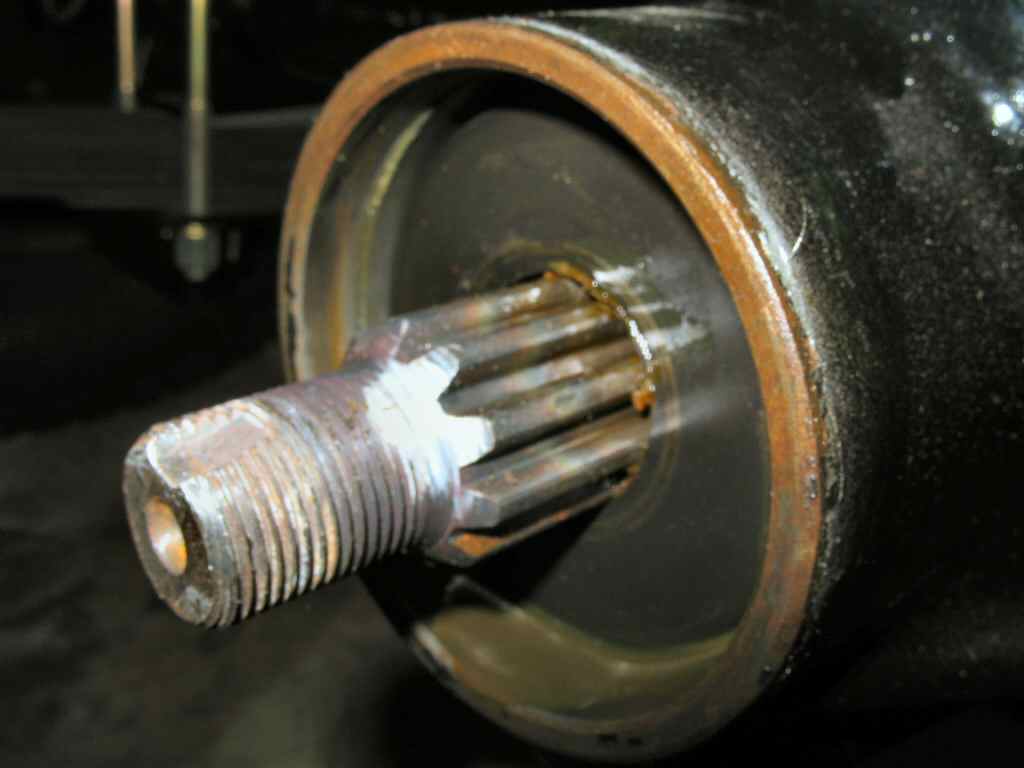
Testing 4 sp shaft Fit
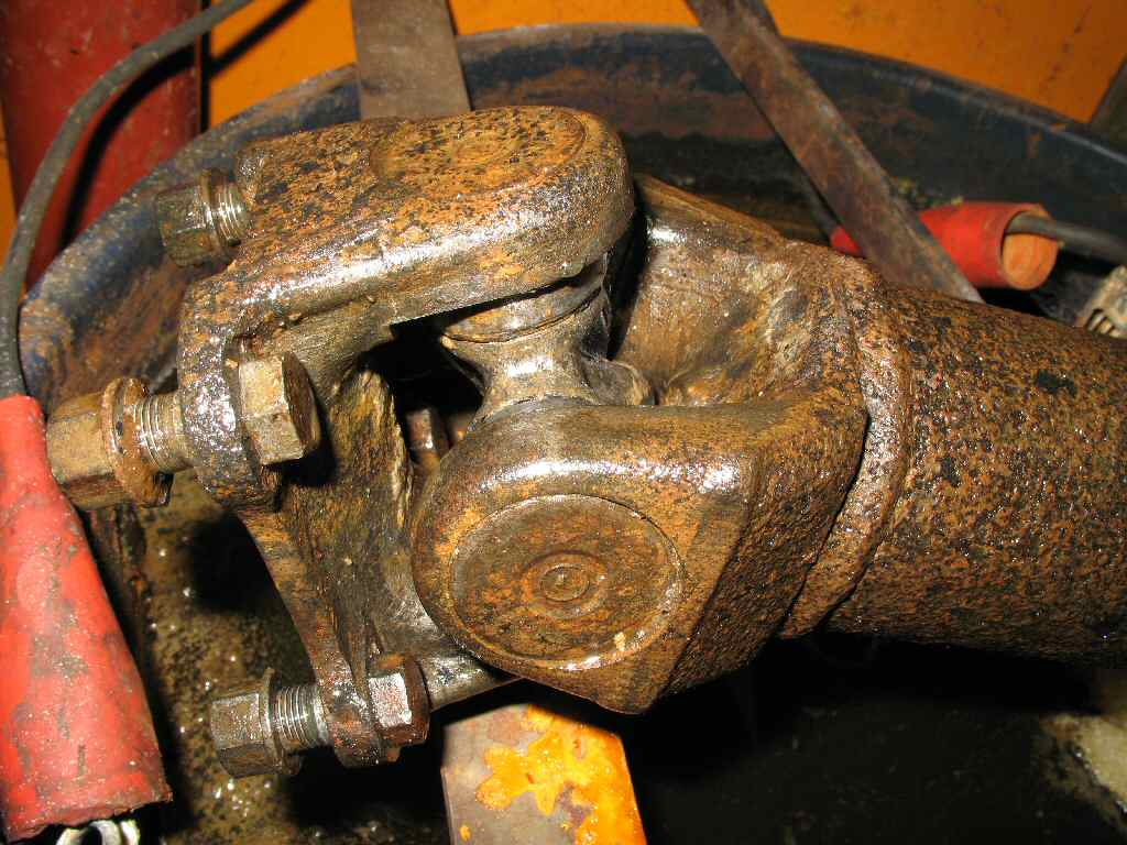
Fig. 2
De-Rusting 1
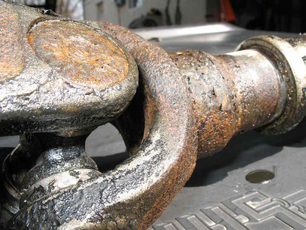
Fig. 3
De-Rust 2
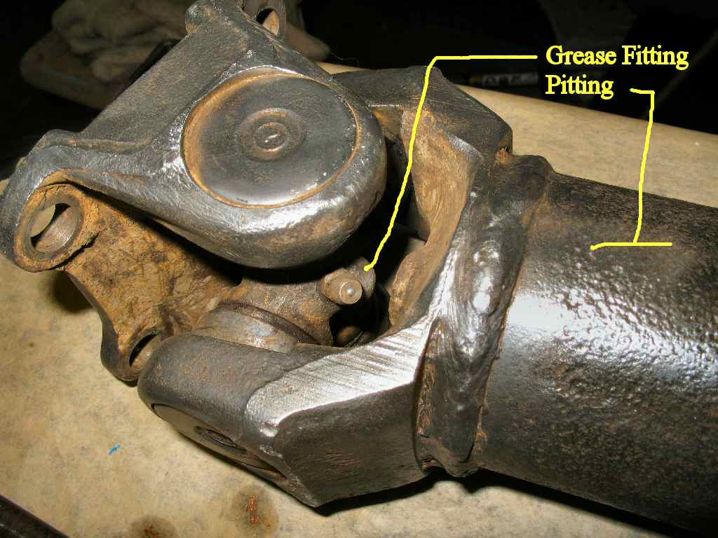
Fig. 4
Mostly Clean 1
Fig. 1 Testing 4 sp shaft Fit |
Fig. 2 De-Rusting 1 |
Fig. 3 De-Rust 2 |
Fig. 4 Mostly Clean 1 |
I decided I wanted to run the 4 sp drive shafts (since I had a good set) so I wouldn't have to have my 3 speed shafts cut. The 4 speed shafts are also stronger then the 3 speed version. Of course nothing being easy on this old Cruiser or cheap I had to spend more money...
After researching on MUD, I found the Cruiser Outfitters (and others) sell course spline pinion flanges with the 4 speed bolt pattern. I ordered two of these. One for the front diff and one for the t-case front output. Though they have different part numbers they are identical. I already had this large pattern flange on the rear diff as that diff is from a later year truck.
I also had to use the 4 sp t-case e-brake drum with the wider spaced bolt pattern and 11mm studs. This is a direct replacement for the 3sp e-brake drum so this part is easy!
After doing a test fit (See Fig.1) with both shafts to be sure they would indeed fit, I started the cleaning up process.
First I put the 4 speed shafts into the parts cleaner to remove what looked like 10 years of grunge from them. Next I put them in my de-rust tank. See Fig. 2-3. This softens up the rust so it becomes VERY easy to remove with a wire wheel on a drill. I stripped them both down to bare metal so I could check for any problems. They were badly pitted but I don't think that will hurt them too much. See Fig. 4.
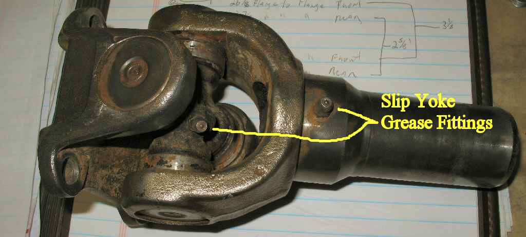
Fig. 5 Slip Yoke |
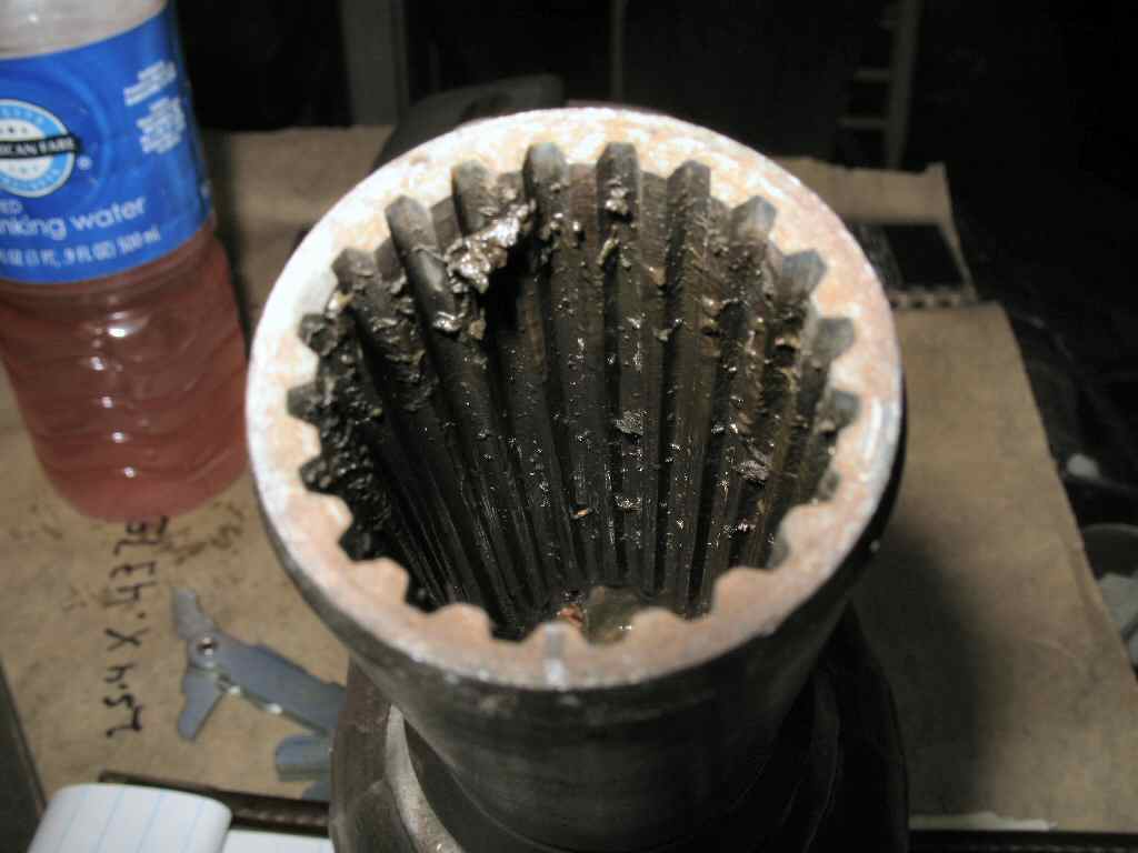
Fig. 6 Dirty Spline's |
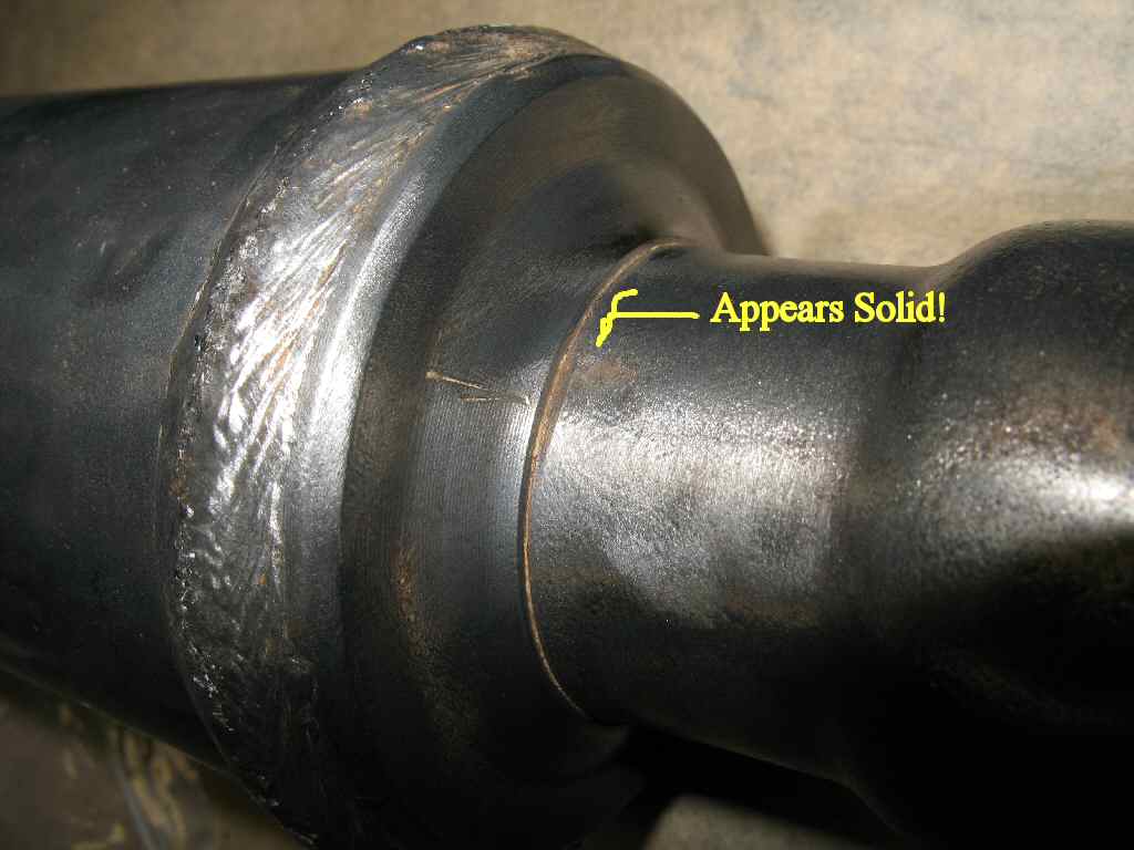
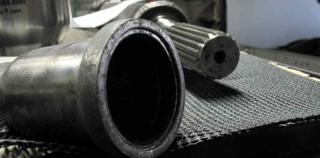
Fig. 7 Looks like one piece?
|
I pulled the slip yoke off to check the spline's and clean out the old grease. They were fine...
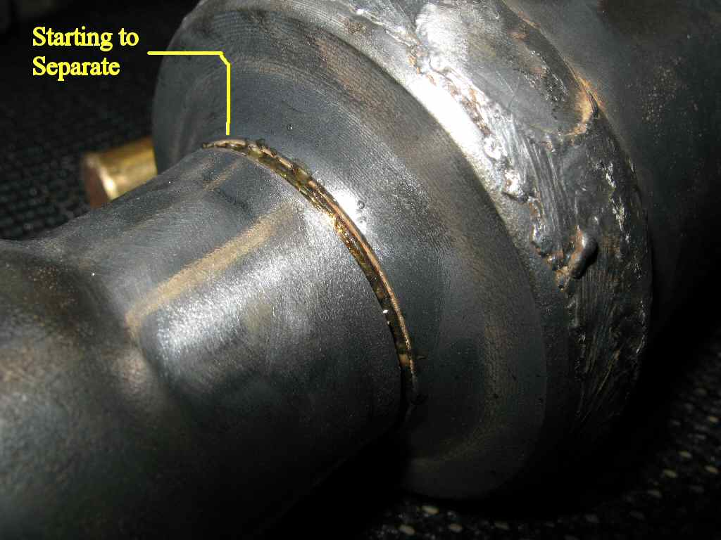
Next I decided to pull the dust seal cover off so I could replace the felt seal. The what, you ask? The FSM there was a felt dust seal and the whole metal cover would come off. (BTW don't bother with this step, as far as I know, the seal is not available.)
I looked closely and all I could see was the seal but did not see how it came off. See Fig 7. The FSM said to pull the dust seal cover by whacking the large end where the dust seal. So I did...
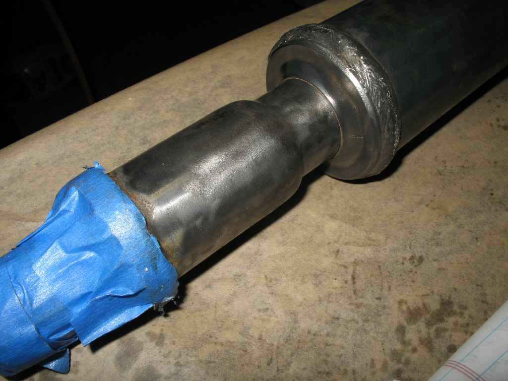
Fig. 8 Whack Here |
Fig. 9 Coming Apart |
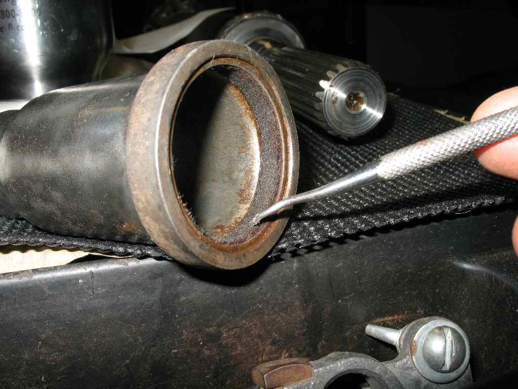
Fig. 10 Dust Seal |
Fig. 11 Another View |
Fig. 8 shows where to whack. The blue tape was to keep rust dust off the spline's. Don't bother taping it, you have to clean them anyway after pulling the dust cover! A few whacks and I could see it start to move. See Fig. 9. It is a press fit so whack pretty hard. In Fig. 10 the cover is off and I'm pointing out the felt seal. It might be possible to make your own but the felt looked fine on this 1976 shaft. All I did was soak it in 90W and whack it back on. High tech stuff here so pay attention! :)
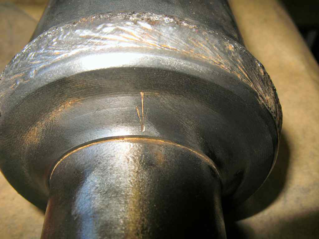
Fig. 12 Index Arrow |
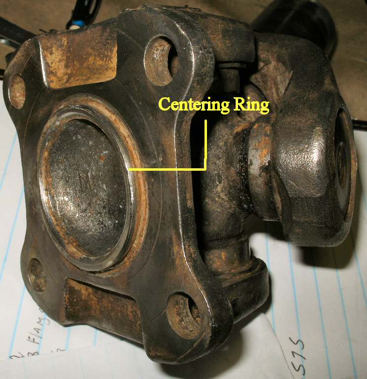
Fig. 13 Indexing Ring |
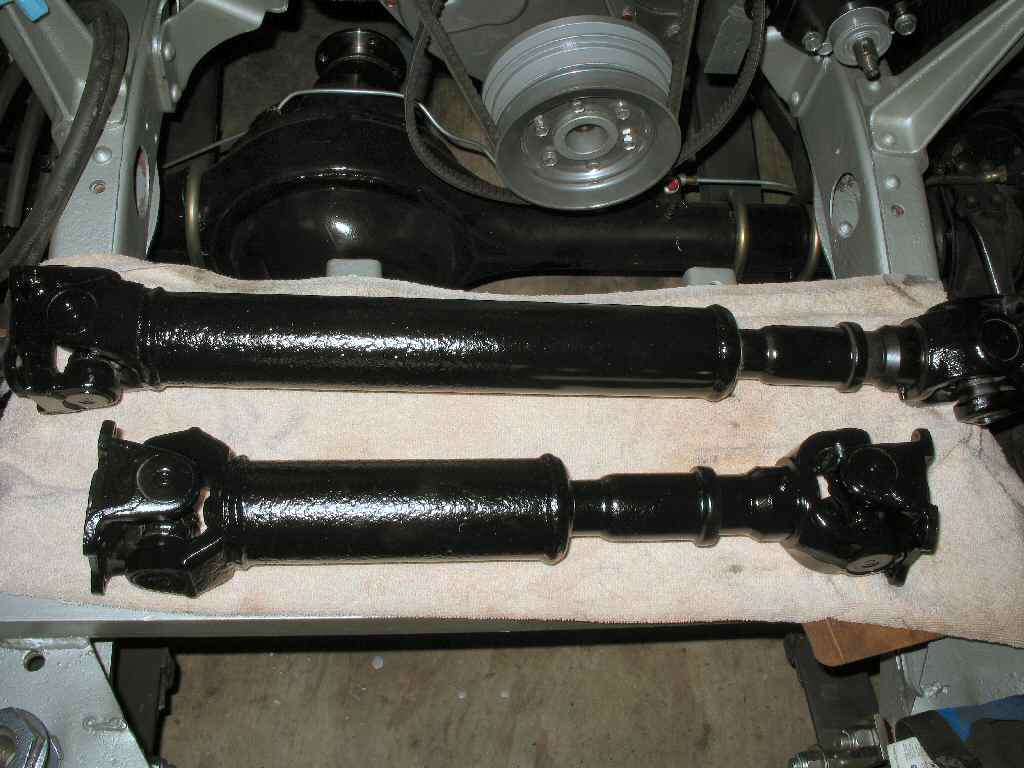
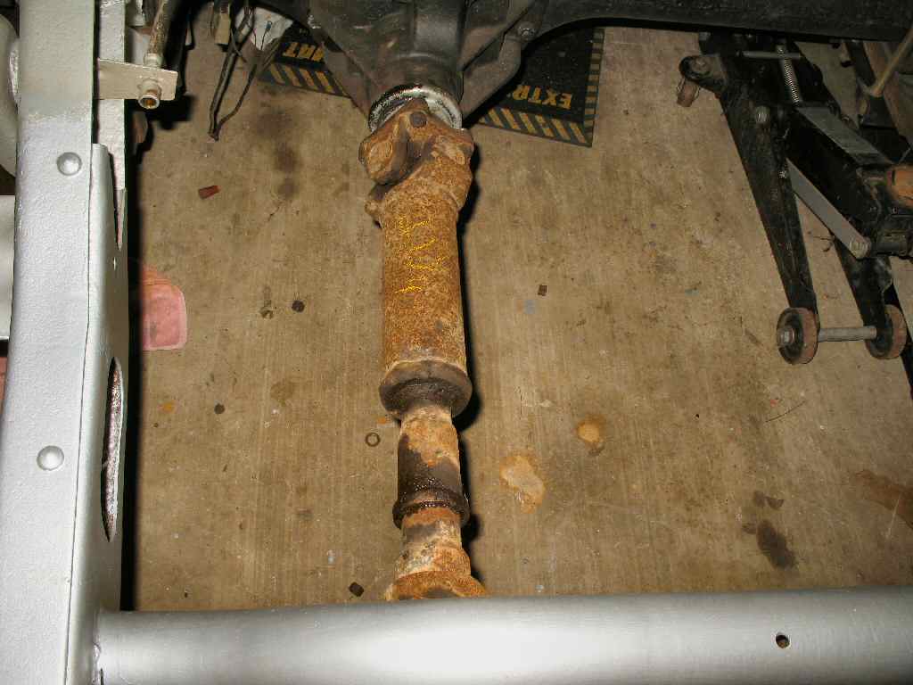
Fig. 14 Painted! |
Many folks, including me, wondered about how you are supposed to ensure the yokes are in phase so the drive shaft does not vibrate. Toyota made it very simple, but, you must have a clean shaft! Fig. 12 shows the arrow Toyota so thoughtfully stamped into the collar. All you have to do is line this arrow up with the grease fitting on the yoke and you will have the yokes in phase!
The other feature I wanted to point out about the drive shaft, is the centering, or index ring cast into each yoke. You can see this ring in Fig. 13. The purpose of this ring is to center the drive shaft on the pinion flange. This ring sets in the recess cast into the flange. All you have to do is rotate the shaft to align the bolts holes.
Finally Fig. 14 shows my de-greased, de-rusted, phased and painted shafts... The U-joints are in good shape so they were not removed and replaced.
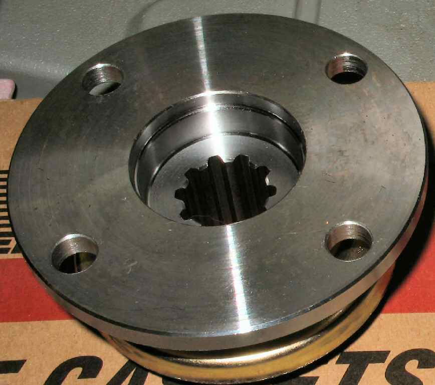
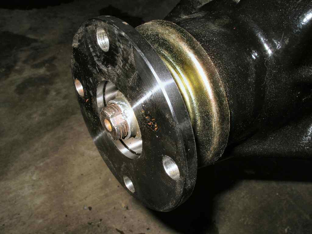
Fig. 15 New Flange
|
Fig. 16 Flange Removed |
Fig. 17 Seal Removed |
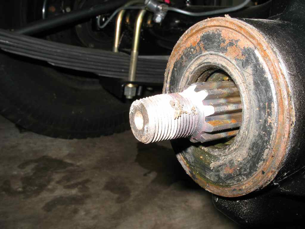
Fig. 18 New Flange |
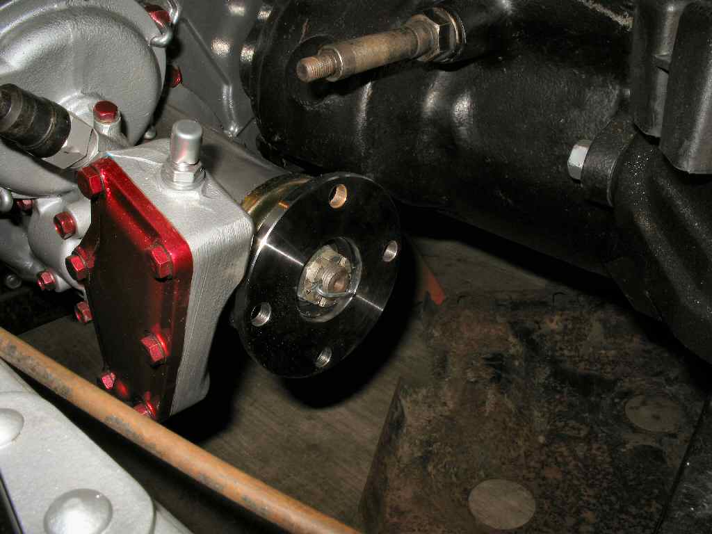
Fig. 19 T-Case Flange Installed |
Ok, now we move to the last phase of the 4 speed tranny into my Cruiser: Swapping to the 4 speed large bolt pattern pinion flanges. As mentioned earlier, I had ordered two of the flanges shown in Fig. 15 from Cruiser Outfitters. These things are NICE!
I started with the front diff. First I removed the old flange, (See Fig. 16 ) and discovered why you really should not sand blast anywhere near the differentials without completely wrapping them to keep sand out! Thankfully no sand got past the old seal but it would have destroyed the seal in a short time had I ran it. I will be replacing the rear seal now... :(
I pulled the old seal out (See Fig. 17 ), and cleaned up all the sand. Make sure to have a drip pan ready to catch the 90W that will come running out. Doh! I popped in the new seal then installed the new flange. Torqued the nut down to 144-173 lb ft, staked the nut and took some pics. See Fig 18. Purdy!
Finally I popped off the old T-Case flange and installed the new one. Torqued the nut back to 101-108 lb ft, installed the cotter pin, and called her good. See Fig. 19.
I'll install the shafts when I finish my rear axle and get some drive shaft bolts .
Hosted by Global Software, Inc.
©1998 - 2023 Mark C. Baker Web Designer
Please: No part of this web site may be used without express permission... email mbaker@globalsoftware-inc.com for permission.