80MS
Installation for 1976 to 1978 FJ40/45 |
||
|---|---|---|
|
|
||
|
Low Brake Fluid Switch Installation for 1976 to 1978 FJ40/45 with an 80 Series Master Cylinder with switch in the cap. Tools needed: Solder iron at least 25 watts, higher is better, wire stripper/cutters, open barrel crimp tool, heat gun or lighter to shrink the heat shrink. Materials needed: Rosin core solder .
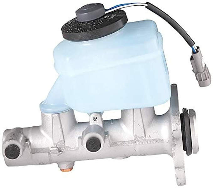
80 Series Master Cylinder
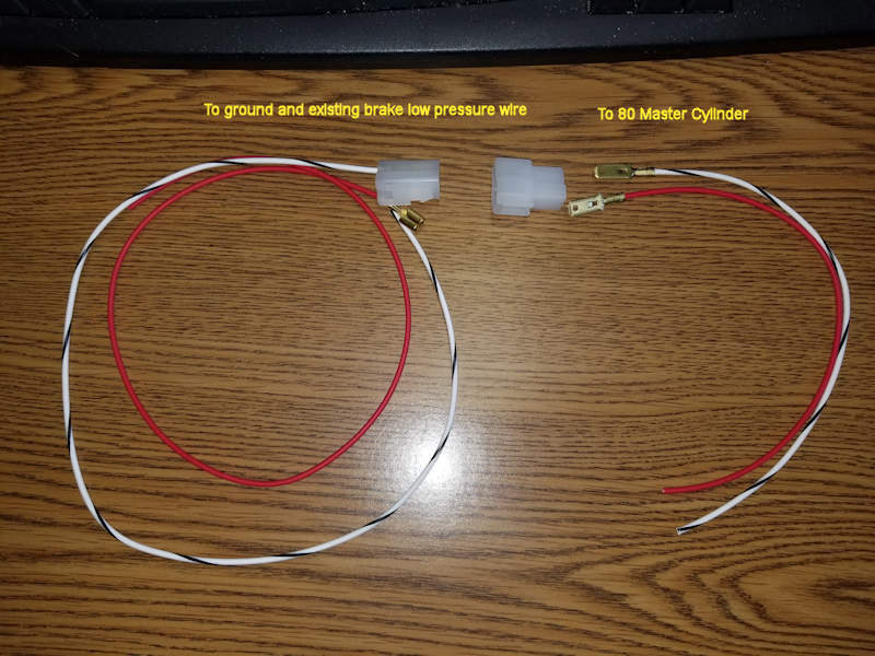
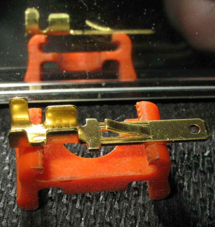
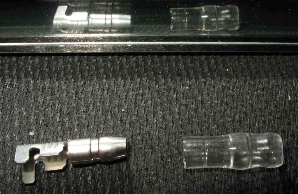
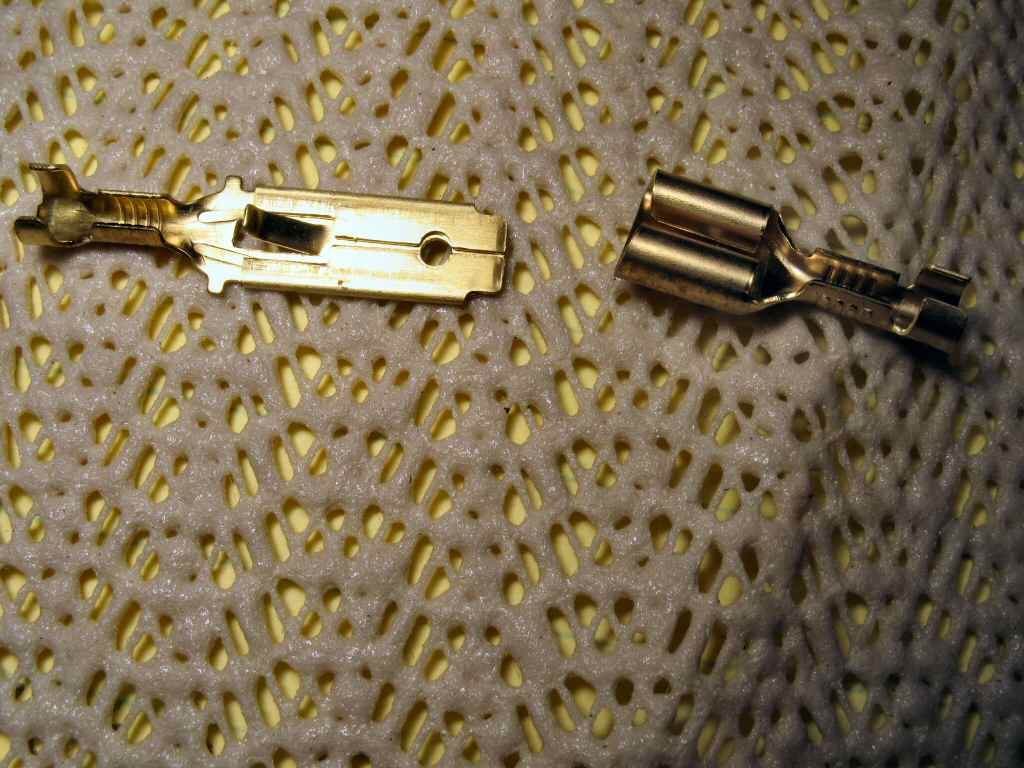
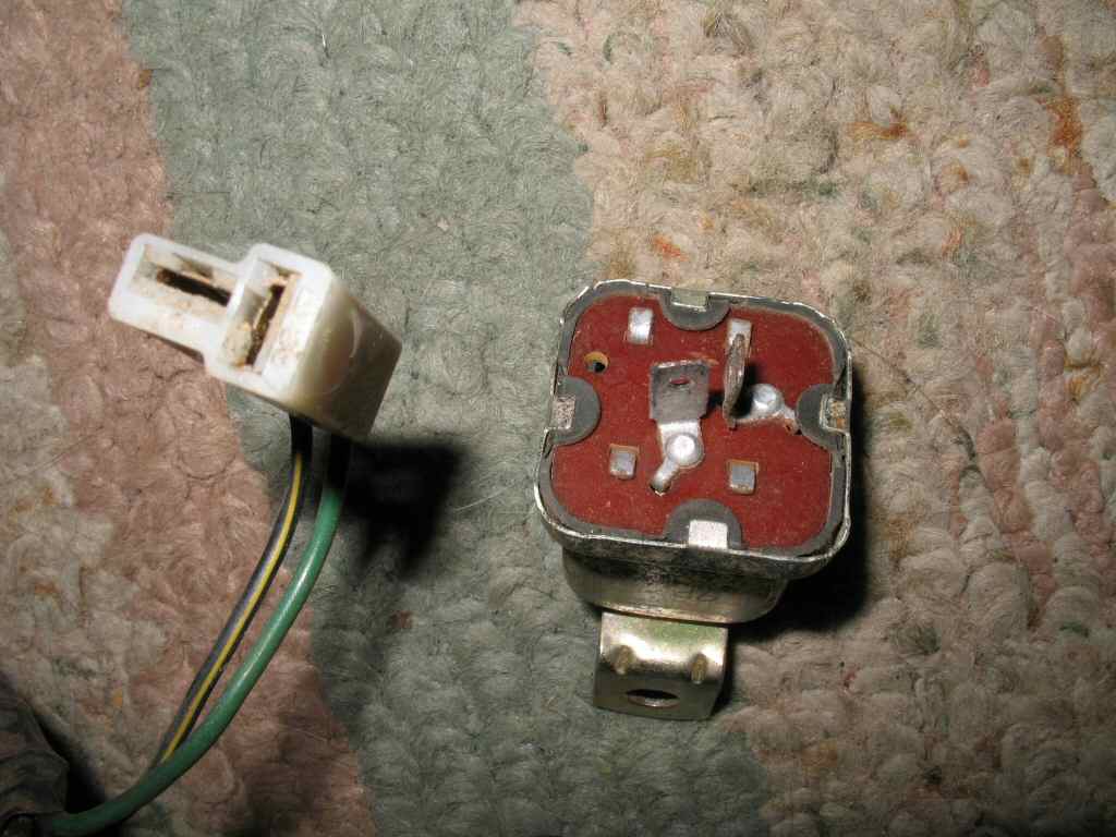
Fig. 1 Cap switch Adapter Wires and Connectors
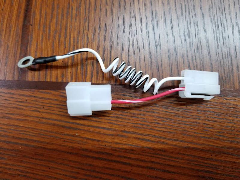
Fig. 2 Park Brake Switch Ground Wire Installation1. Disconnect the + AND - Battery terminals from the battery! I can't stress this enough... 2. Let's start at the Master Cylinder. The 80 Master
Cylinder has a factory installed two pin electrical connector that
is connected to a float switch inside the fluid reservoir cap. Unfortunately
the mating connector is no longer available so we need to replace
it with the two pin male connector provided in the kit. Cut the
OEM connector off. Strip 1/8" insulation off the two wires
coming out of the Master Cylinder. Crimp on the two included male
terminals. Insert the two male terminals into the male connector
body so they match the wires in the female two pin connector in
the kit. Now we need to address the Park Brake Switch. Because of the way the OEM, system low pressure sensors originally worked, you will have to provde the Park brake switch with its own separate ground in order for the Park Brake Switch to light the Brake light. That is what the adapter with the two pin connectors and the curly white/black wire is for. 1. Locate the Park Brake Switch under the dash. It will have two wires coming out of it terminated with a male two pin connector and should be plugged into a matching two pin female connector. Unplug the Park Brake Switch from the female connector. Plug the provided adapter in between the Park Brake Switch and the two pin female connector. 2. Finally place the ring terminal of the White/Black curly ground coming off the adapter wire under a bolt on the firewall close to the Park Brake Switch. Now your Park Brake Switch has its own ground. You're Done!
How The OEM System Works
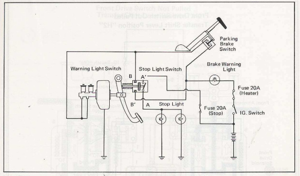
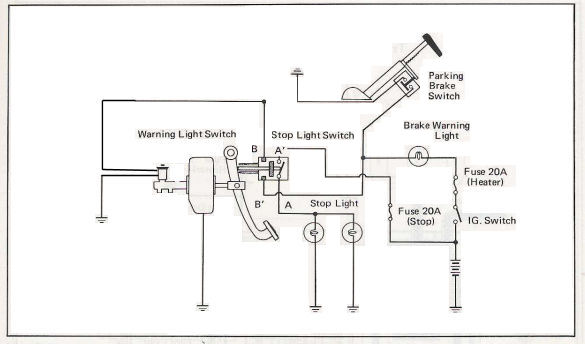
HydraulicsI'll start with explaining how the OEM Low Brake Pressure Sensors themselves work. The sensors first off are simple Normally CLOSED pressure switches. They are screwed into the bottom of the master cylinder so they detect brake fluid PRESSURE in the front and rear brake circuits. When the brake pedal is NOT pressed, ie there is no pressure in the two brake circuits, the switches in the sensors are CLOSED. When you press the brake pedal down, pressure builds in the master cylinder, and when the pressure reaches the set point of the switches, they OPEN. ElectricsFYI! The correct brake light switch for this circuit is a 4 wire switch that contains TWO sets of normally OPEN contacts, A and B. The A set is for the actual brake lights and the B set is for the Low Brake Pressure Warning circuit. Be aware that a lot of aftermarket switches are only two wire and do NOT contain the B set of contacts! Make sure you have the correct switch installed. OEM Circuit DescriptionRefer to the schematic above. The initial conditions are this: The key switch is on, the brake pedal is NOT being pushed, and the Park Brake is NOT on. The Low Brake Pressure/Fluid Warning Lamp is OFF. One side of the pressure switches are connected directly to ground through the master cylinder mounting bolts and the other side of the switches are connected to the low brake pressure lamp through the main brake switch. When you first turn the key to on (not start) the Low Brake Warning lamp is NOT on (unless the Park Brake is ON, see below for a description of how that circuit works). At this point, if you LIGHTLY press the brake pedal, two thing happen. First, BOTH sets of contacts in the 4 wire brake switch CLOSE. So the brake lights come on, and for a second, the Low Brake pressure Warning lamp comes on. Why? At this point there is no pressure built up in the brake circuit so the brake pressure sensor switch is still CLOSED and connected to ground. Follow the schematic and you will see that the circuit to the bulb is now complete from ground, through the pressure sensor switches, through the B set of contacts in the 4 wire brake switch, through the bulb and finally to +12V. So the bulb lights. Now if you press a little harder, pressure starts building in the brake circuit to the point that the brake sensor switchs both OPEN. When the switchs open the lamp goes out. Now you may be wondering why the lamp does not light up while driving down the road and your foot is not on the brakes? Since the low brake pressure switch has to have enough pressure in the circuit to keep it open, (to keep the lamp from lighting), where does this pressure come from if your foot is not on the brake? In FJ40's with a drum brake master cylinder, Toyota installed what are called residual check valves. The residual check valves do three things. The primary job is to keep 5-12 psi on the wheel cylinder cup seals. Since there is always 5-12 PSI of pressure in the system, any small leaks in these seals result in brake fluid leaking out instead of air leaking into the system. Air is the system is not good. The second purpose of these valves is to provide a firmer feeling brake pedal and to keep pedal travel lower. Think of it as pre-pressurization of the system. The third thing they do is to keep the low brake pressure switchs OPEN. So when you first apply the brakes, the pressure builds up until it passes the rating of the residual valve which then closes keeping the pressure in the system. Overnight the system pressure will eventually bleed off which is why the lamp lights for a second when you first hit the brake pedal. If a major leak develops in either the front or rear brkae circuit the pressure falls below the level of the check valve causing one or the other of the switchs to close and the Low Brake Pressure Warning Light will come on when the brake pedal is depressed. OEM Park Brake On LightThe Brake Warning Light also serves as a warning light to let you know the Park Brake is set. The Park Brake has a single contact switch built into its mechanism. This switch is wired in parallel with the two low brake pressure sensor switches. Refer to the drawing above and set the Park Brake ON. Here is how it works. When you first turn the key on, and the brake pedal is NOT being pressed, there is NO pressure in the brake system, so the low brake pressure sensor switches are both CLOSED. This provides a path the ground through the Park Brake Switch to the warning lamp which now lights letting you know you left the Park brake on...
How the Modified System Using the 80 Series Cap Switch Master Cylinder Works
Ok! If you made it this far, you are a dedicated Cruiser Head! Pardon my crude modification of the above drawing. I have trouble drawing a straight line with a computer! There are two differences in this modified system versus the OEM: The Brake Warning Light is now turned on by low brake fluid level in the master cylinder reservoir, instead of low brake pressure in the hydraulic system, and the Park Brake Switch now has its own separate ground wire. Why? Well since the float level switch is only connected to ground when the fluid level is low the Park Brake switch has to have it's own path to ground in order to light the Brake Warming Light. This is accomplised on the 71-74 FJ40/45 by simply unplugging one side of the Park Brake Switch, plugging in a ground wire with a ring terminal, and grounding that under a bolt on the firewall. For the 75 to 78 FJ40/45 an adapter is plugged inbetween the harness side park switch connector and the Park Brake Switch itself which has a ground wire that is grounded on the firewall. Details are in the installation instructions. The rest of the circuit remains and functions the same. Modified Circuit DescriptionRefer to the modified schematic above. The initial conditions are this: The key switch is on, the brake pedal is NOT being pushed, and the Park Brake is NOT on. The Brake Warning light is OFF. When you turn the key switch to on, +12V is applied to the positive terminal of the Brake Warning Lamp. At this point, if you push the brake pedal down the Brake Warning light is STILL not on due to the float level switch being open. So in order for the Brake Warning Lamp to light, you must be pushing the brake pedal AND the brake fluid level must be low enough to close the master cylinder reservoir float switch. If the brake fluid level is high enough, the lamp does not light. Modified Park Brake On LightRefer to the drawing above and set the Park Brake ON. Here is how it works. When you first turn the key on, +12V is applied to the positive terminal of the Brake Warning Lamp as before. The other side of the light is connected to one side of the Park Brake Switch and the set of Brake Switch contacts that go to the Float Level Switch. Now, due to our mods, the other side of the Park Brake Switch is connected directly to ground instead of going through the low pressure switches to ground. This results in the Brake Warning Light immediately lighting up instead of having to wait to push the brake pedal.
|
||