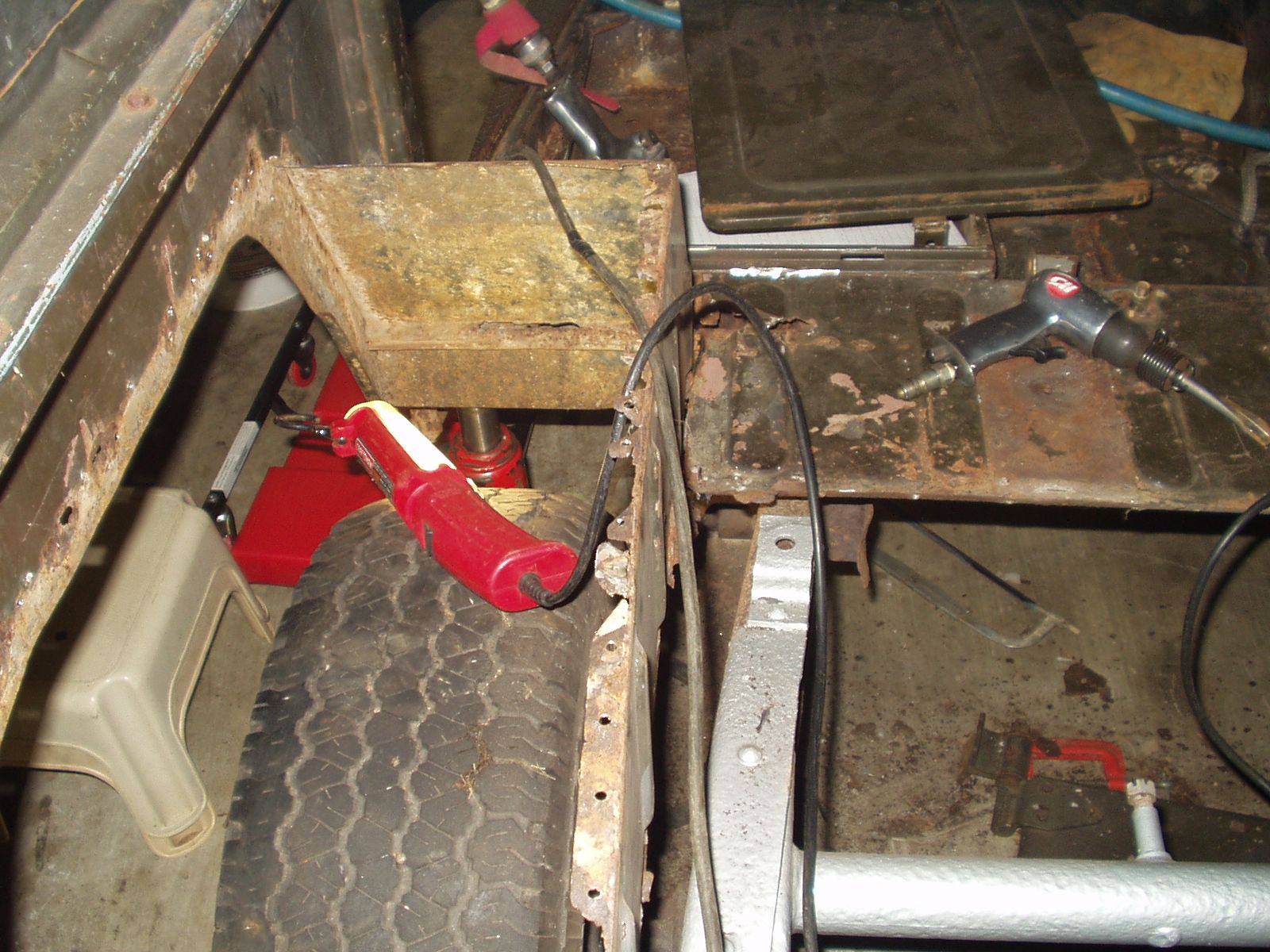
Fig. 1
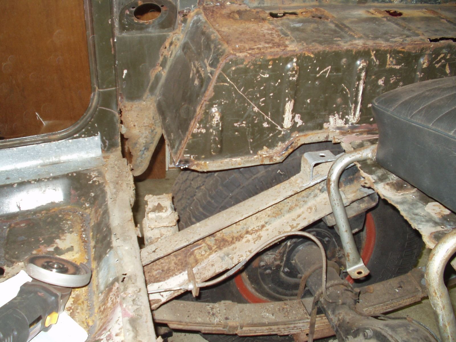
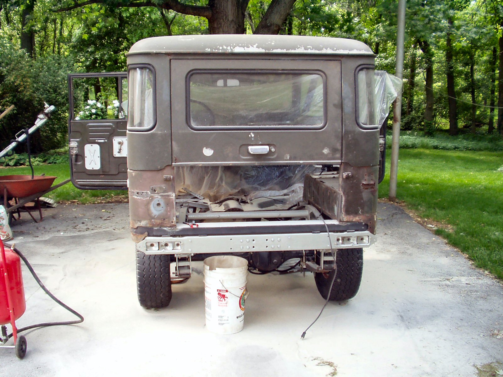
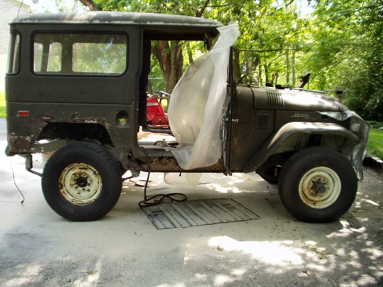
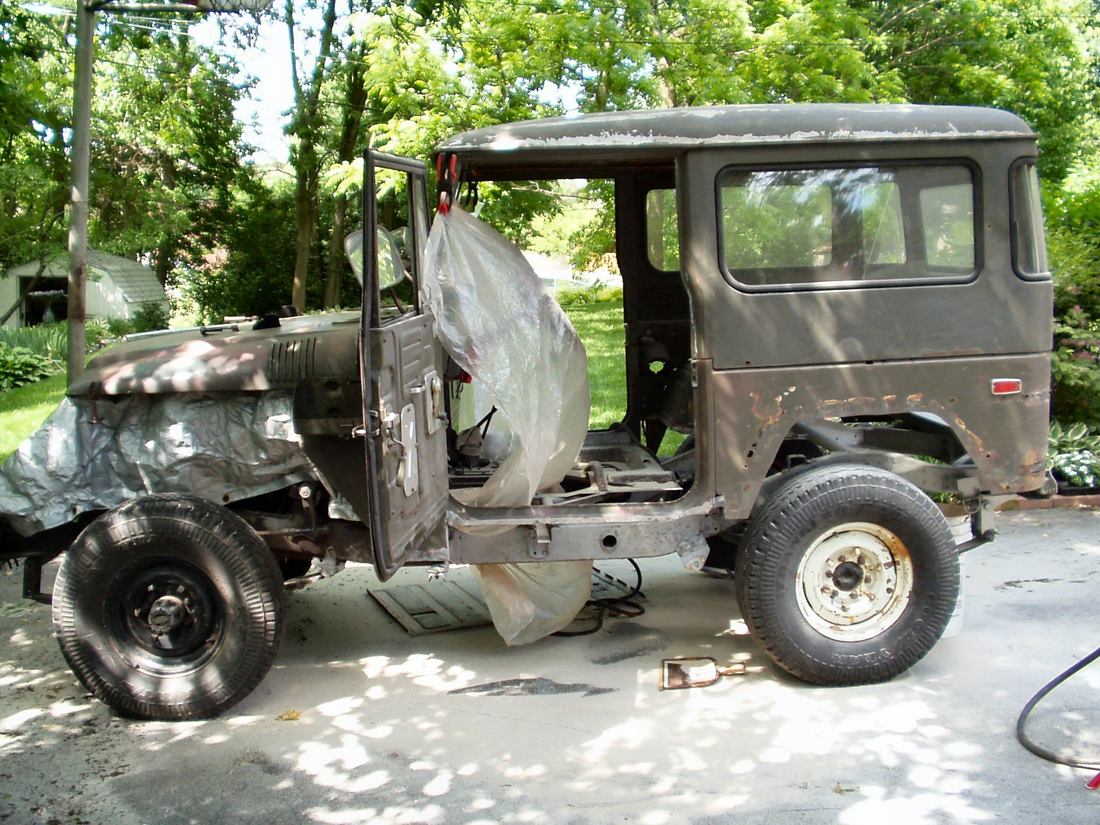
I knew this piece was rusted badly but I had no idea how badly until I started taking the floor pan out. Follow the pics to see just how bad this was and what I had to do to fix it. Here is a slide show of the removal process.
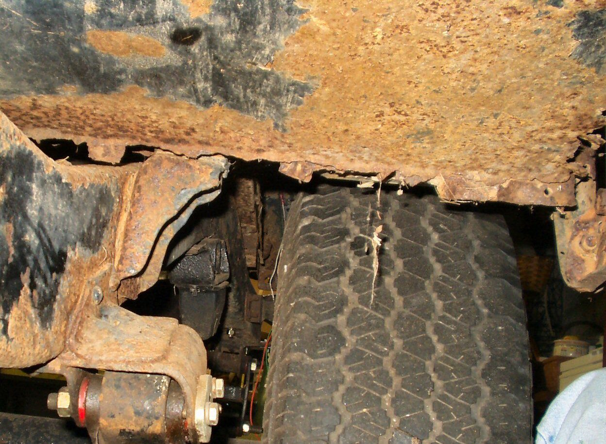
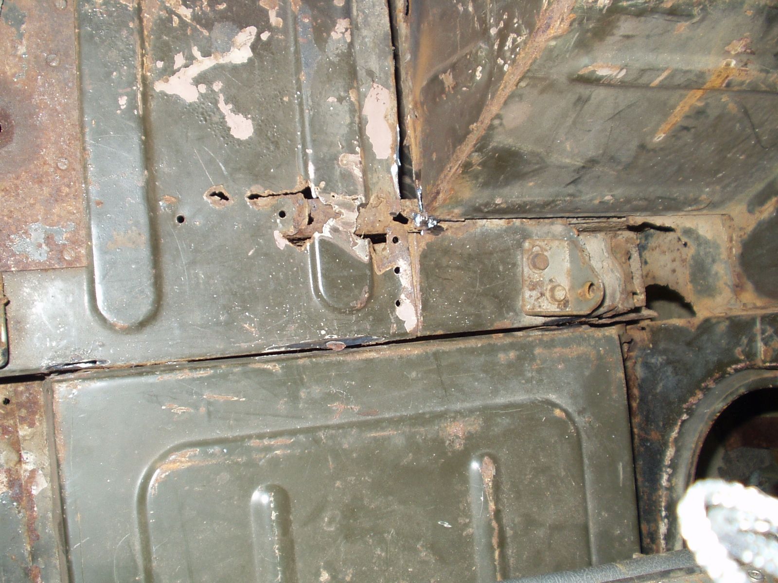
Fig. 2
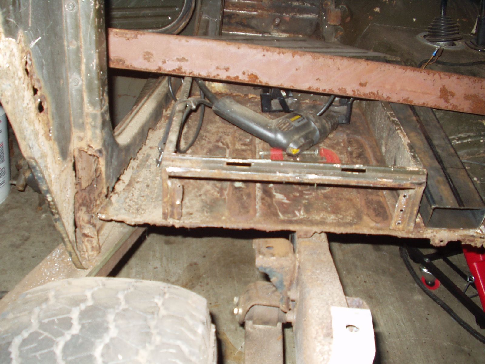
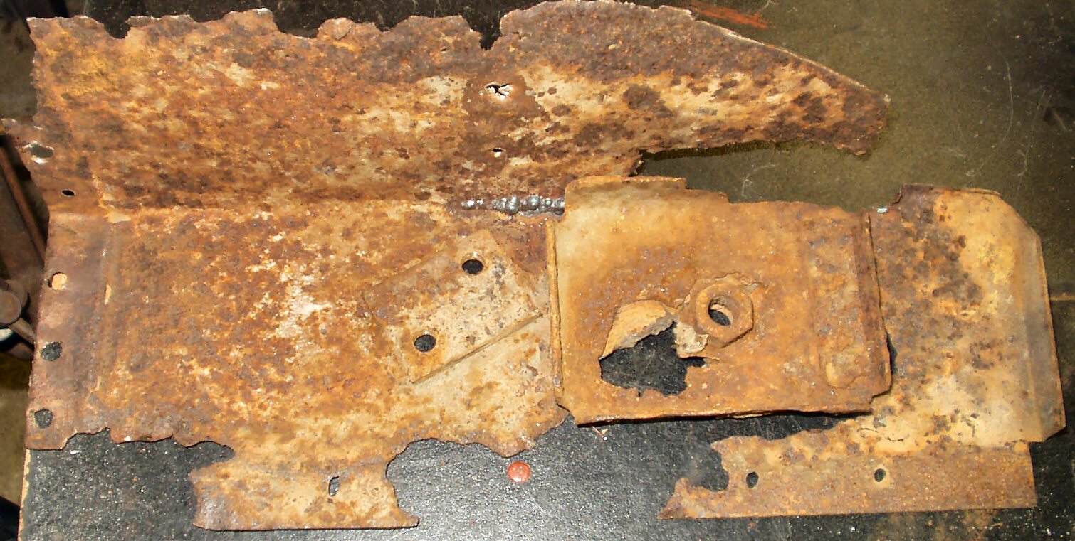
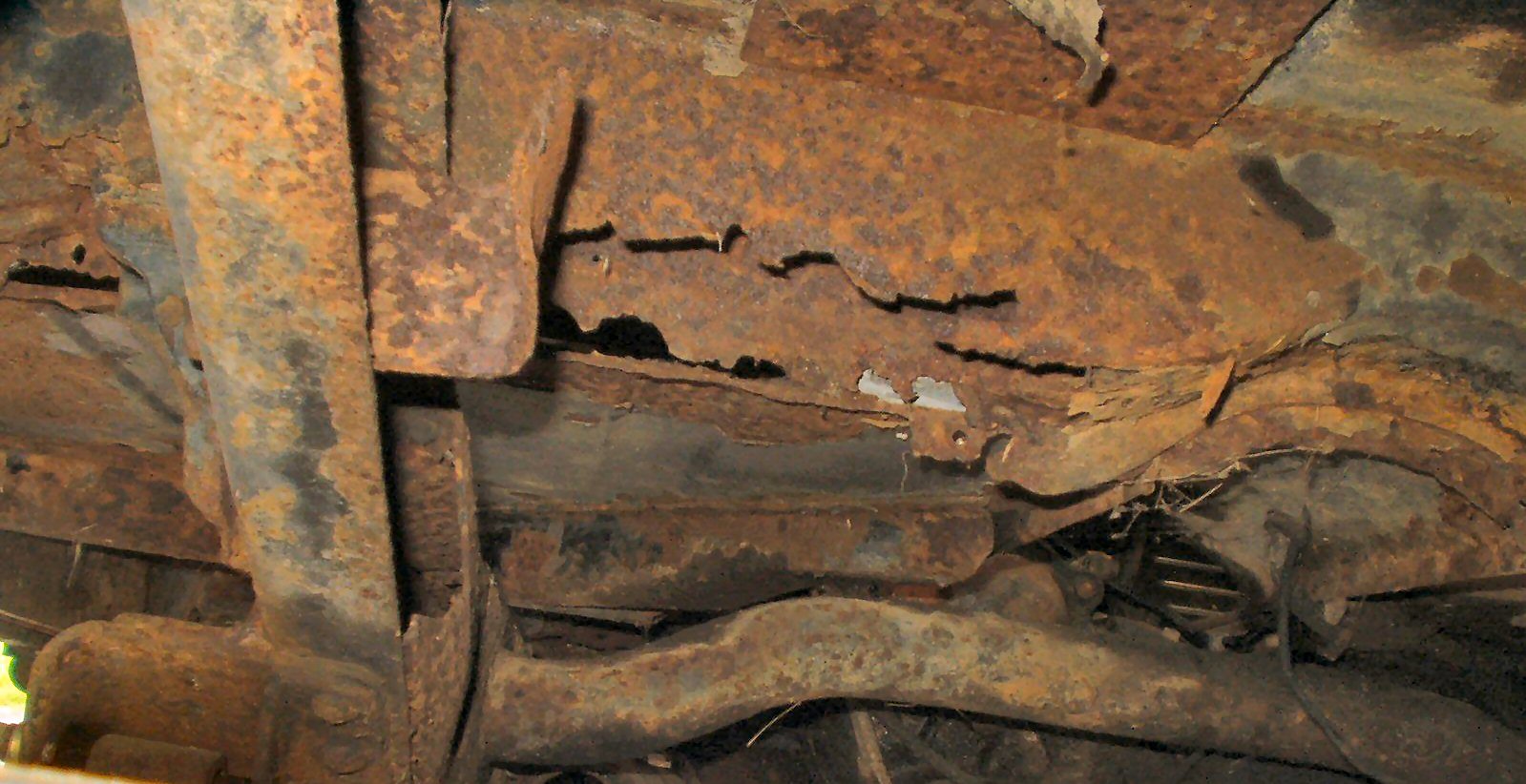
This support was just gone ...
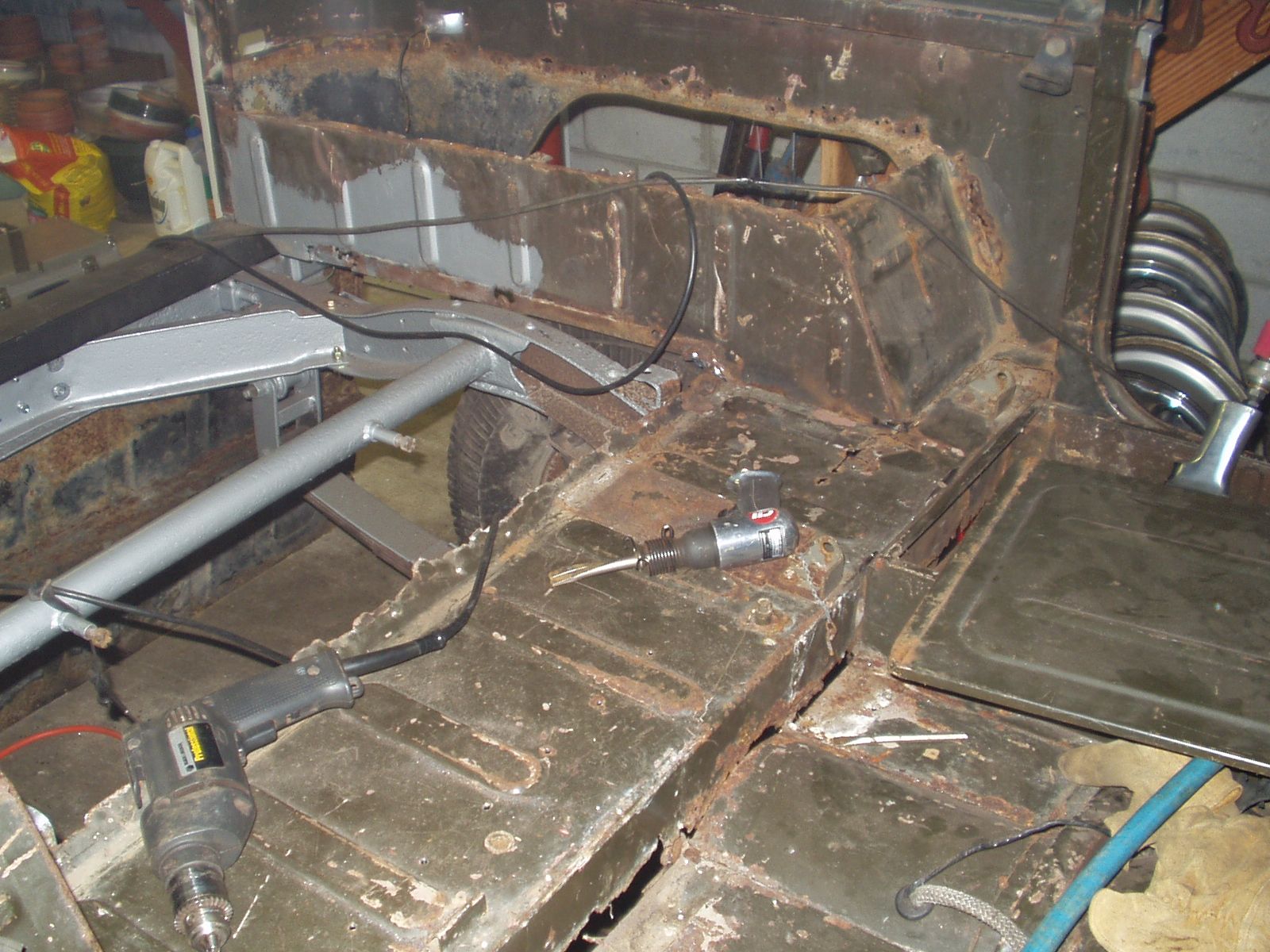
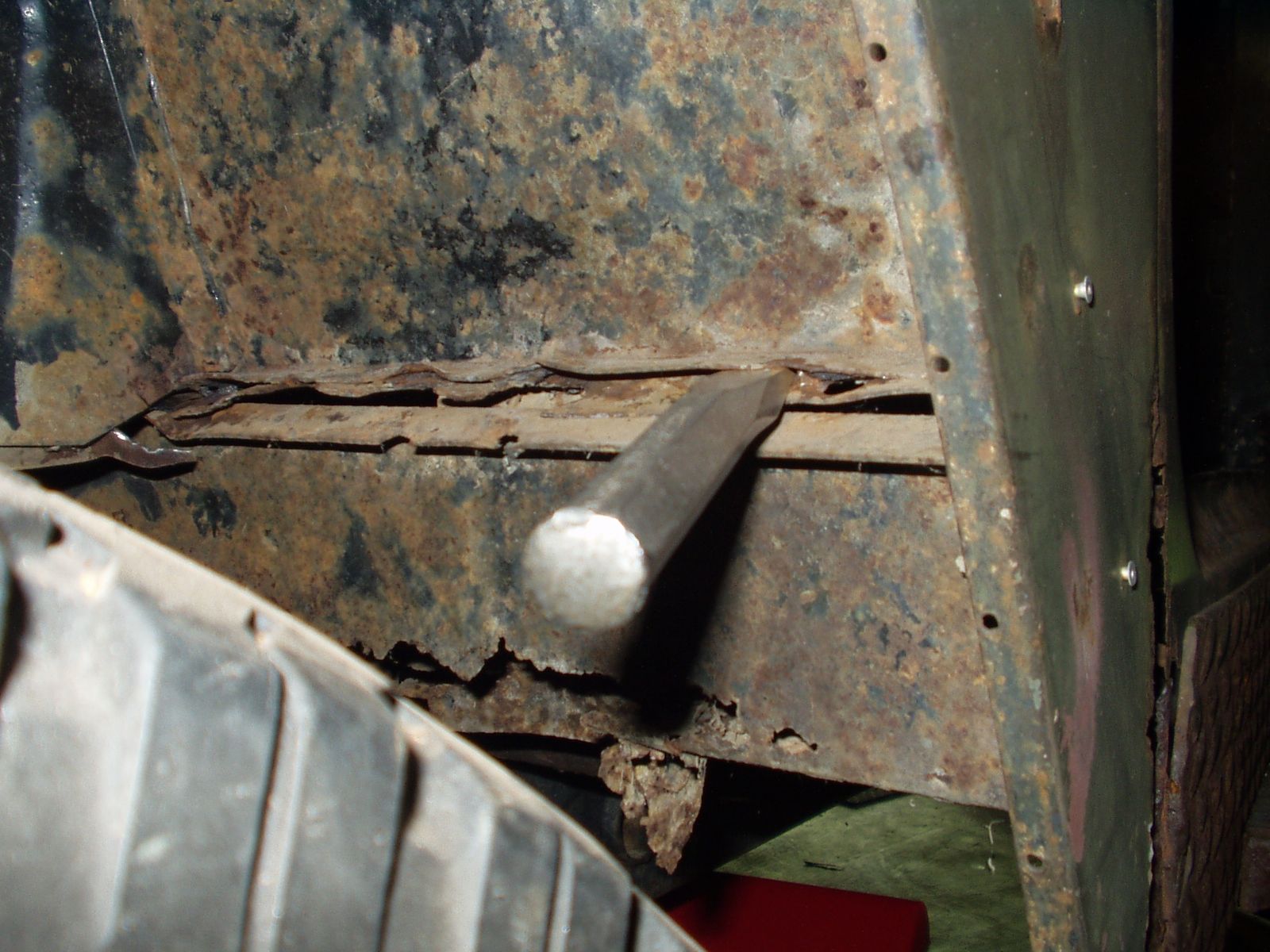
Fig. 3
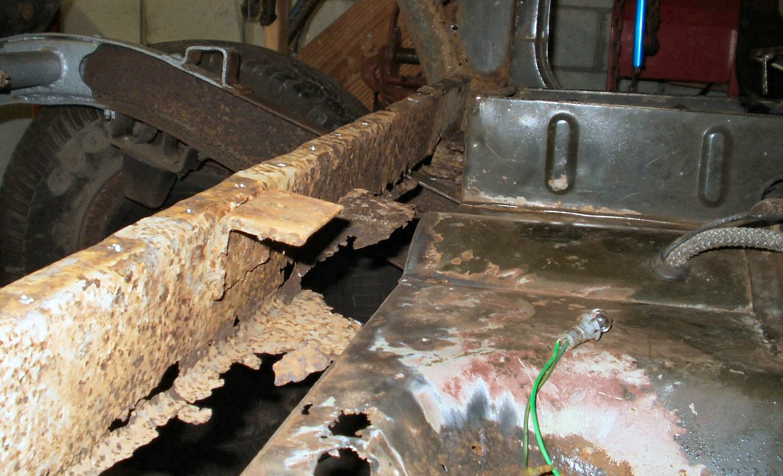
As you can see I will need to buy or fabricate new wheel wells, floor pan and quarter panels ...
Fig.4 |
Fig. 5 |
Fig. 6 |
Fig. 7 |
Fig. 8 |
Fig. 9 |
This took the better part of a weekend to take apart. I used a 1/8" drill bit to drill pilot holes through the spot welds (sharpening the bit after every 10 holes on the Drill Doctor! Cheap ass bits ...) Then I used a 3/16" and a 1/4" bit to actually drill out the weld. An air hammer with a seam separator tool was also VERY handy for the stubborn ones. One thing that threw/surprised me; The back wall of the tool box is completed by the center floor section! See Fig. 7 and 9. When I put it back together I may rectify that.
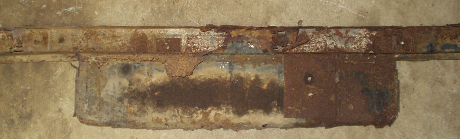
Fig. 10
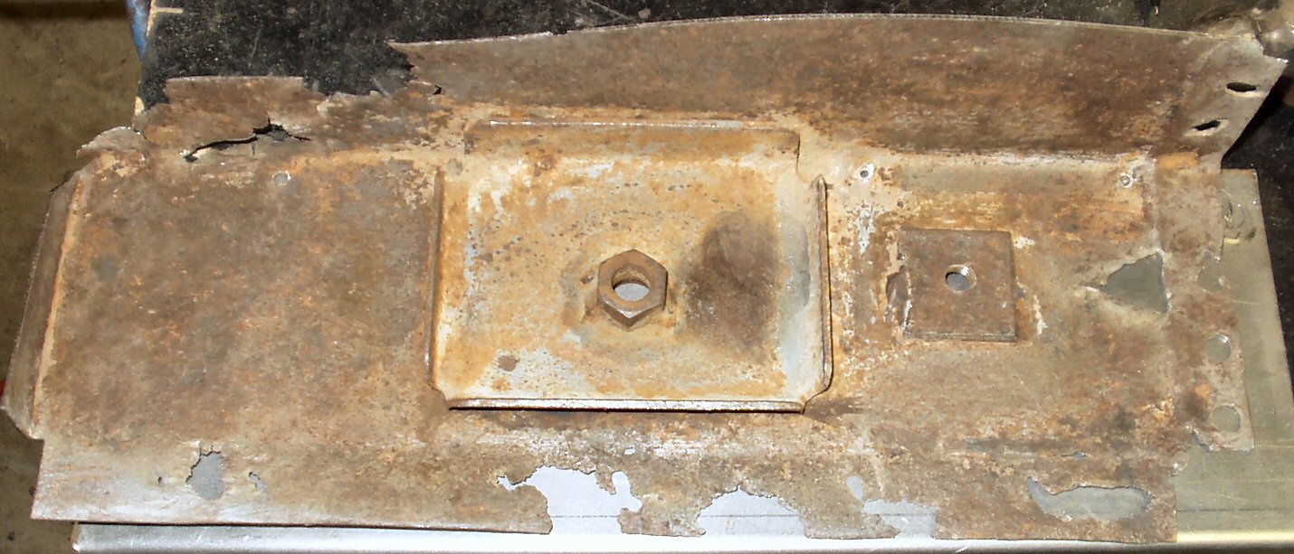
Here is the mid bed support (with the mid bed attached) removed. As you can see there is nothing much left to work with.
Fig. 11 |
Fig. 12 |
This is the actual 'channel' that acts as the support. This is after removing it from the mid bed section and putting the channel back in place in the truck. Making this piece from scratch will be fun city :-) ...
After many months of working on other things on the Cruiser and just life in general I finally got around to working on this part of the Cruiser again. I took many measurements and finally had an order ready for a local sheet metal shop. I had them bend up the following pieces:
Total cost was $230.00 In the meantime I started doing some of the prep work for the job. This involved sandblasting as much of the frame as I could get to with the body still sort of on. When I get the body stable enough and the time and place to do it, I plan to pull the body completely off to do this job right. For now I just need to get it ROAD LEGAL and out of the garage!
Fig. 13 Making a mess |
Fig. 14 Snow In May? |
Fig. 15 The frame is actually there! |
Fig. 16 Who is dirtier? |
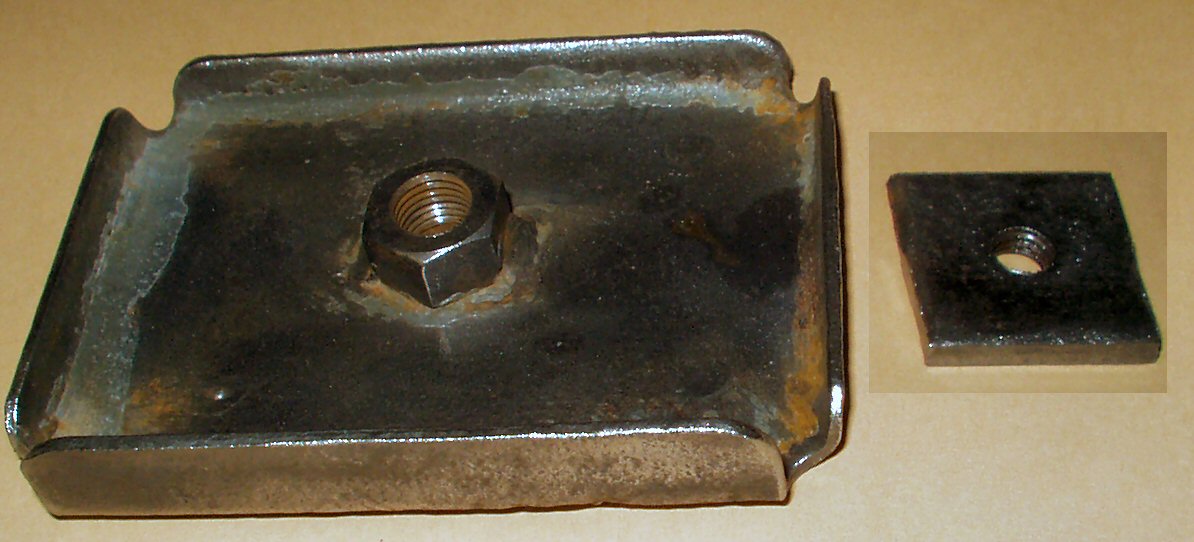
If you have never taken your earlier Cruiser this far apart you may not know what the various pieces like the seats, seat belts and heater are actually 'bolted' into. Toyota uses 1/4" thick, tapped backing plates welded to the bottom of the sheet metal. Of course my 'new' center channel nor mid bed end pieces have these backing plates. So where they were not too badly rusted I cut out the old ones, de-rusted them then welded them into their proper places on the new pieces after careful measuring and test fitting. Follow along as I go through each piece....
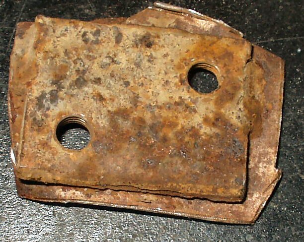
Fig. 17 What was left of the drivers side Mid Bed End Piece |
Fig. 18 Drivers Side Seat Mount Backing Plate removed |
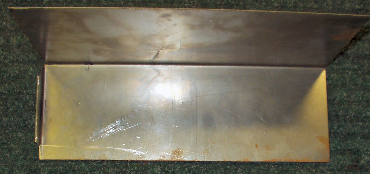
Fig. 19 New Drivers Side End Piece
|
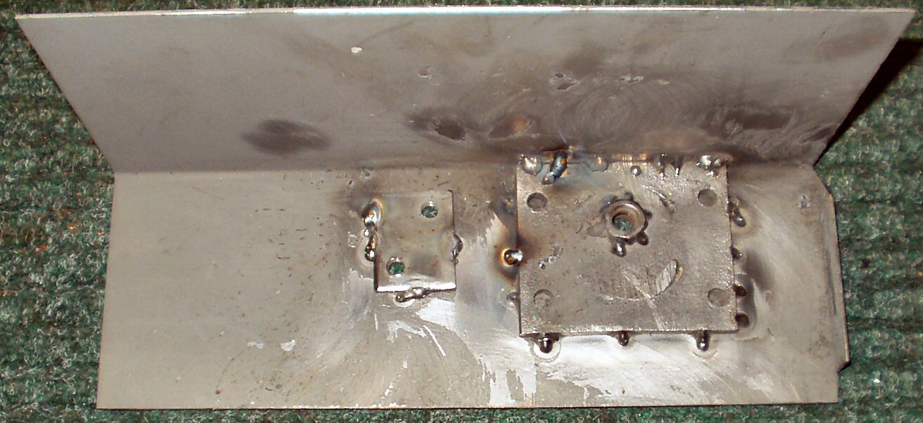
Fig. 20 Cleaned Backing Plates Welded on new panel |
There was not much left of the drivers side mid bed end piece. See Fig. 17 The only thing salvageable was the driver seat rear mounting backing plate. I used tin snips to cut around the plate then took it to the grinder and ground down the welds that held it to the sheet metal. See Fig. 18. Next I found a 1/4" thick by 4" X 4" piece of scrap and drilled a 1/2" hole in the same position as the old seat belt mount plate then put it, a 12mm x 1.25 nut and the old seat mount plate in the de-rust tank. In the meantime I was looking at the photos and measurements I had taken earlier while tearing it apart to determine where the pieces would need to mount. This had to be pretty close or the seat would not bolt in correctly! I had to put several body pieces back in the truck to ensure they would all line up properly. I'm sure when I actually start to reassemble it I will have to do some 'adjusting'!
After the parts came out of de-rust I used them and the measurements I had to mark the holes in the new end piece. Those holes were drilled, the pieces were bolted in place then the piece was test fitted several times to make sure it would fit. Next I welded the nut to the backing plate for the seat belt mount.
At this point I was about to go on vacation and remembered that there was a discussion on the LCML about using weld through primer on parts that would be welded together with butt laps then sealed up once welding was done. I looked around, found the thread and ordered a couple of cans of weld through primer from Grainger. DEM-KOTE Part # 6MT29. $3.47 per can. They would be there when I returned. Well I came back I opened the box and there were two cans of what appeared to be just standard primer. I double checked the number of the product then looked on the can and sure enough it said this primer had a high zinc content. However it did NOT specifically say it could be welded... So like an idiot I coated all the pieces with the primer, let them dry then bolted the parts together and started trying to weld them ... Fig. 20 shows the results of the attempts. Weld thru my ass! It popped, sputtered, and the weld metal absolutely would not 'stick' until the primer burned off! The welds were horrible even by my standards. I ended up grinding all the welds off then putting the parts into the de-rust tank to remove the primer. It did not take long as it had not adhered well at all. Grrrr.... Lesson learned the hard way on that one, you get what you pay for. Get the GOOD weld thru primer!
Fig 21 Old Passenger Side End Piece |
Fig. 22 New Passenger Side End Piece |
Fig. 23 Side View |
Fig. 24 Old Backing Plates Removed |
Fig. 25 Mounting Plates To new panel |
Fig. 26 Primed |
The old passenger side end piece was in a bit better shape. See Fig. 21. I was able to salvage both backing plates for the new panel.
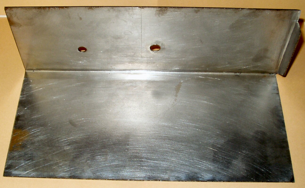
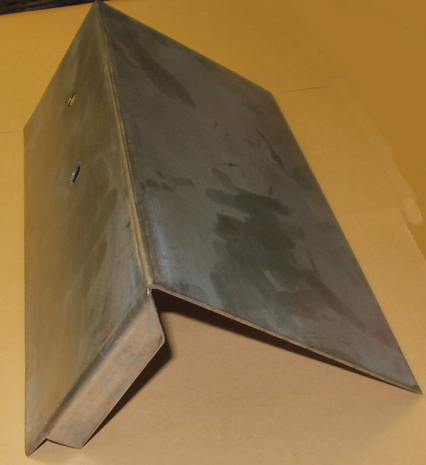
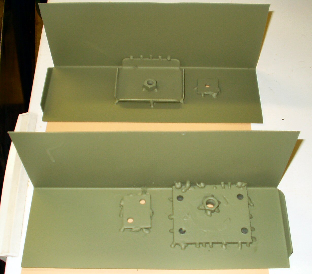
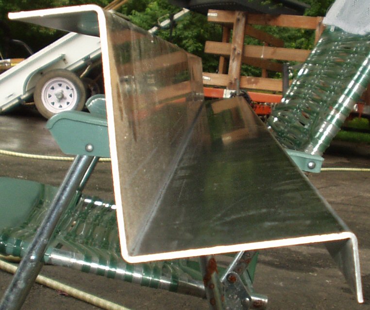
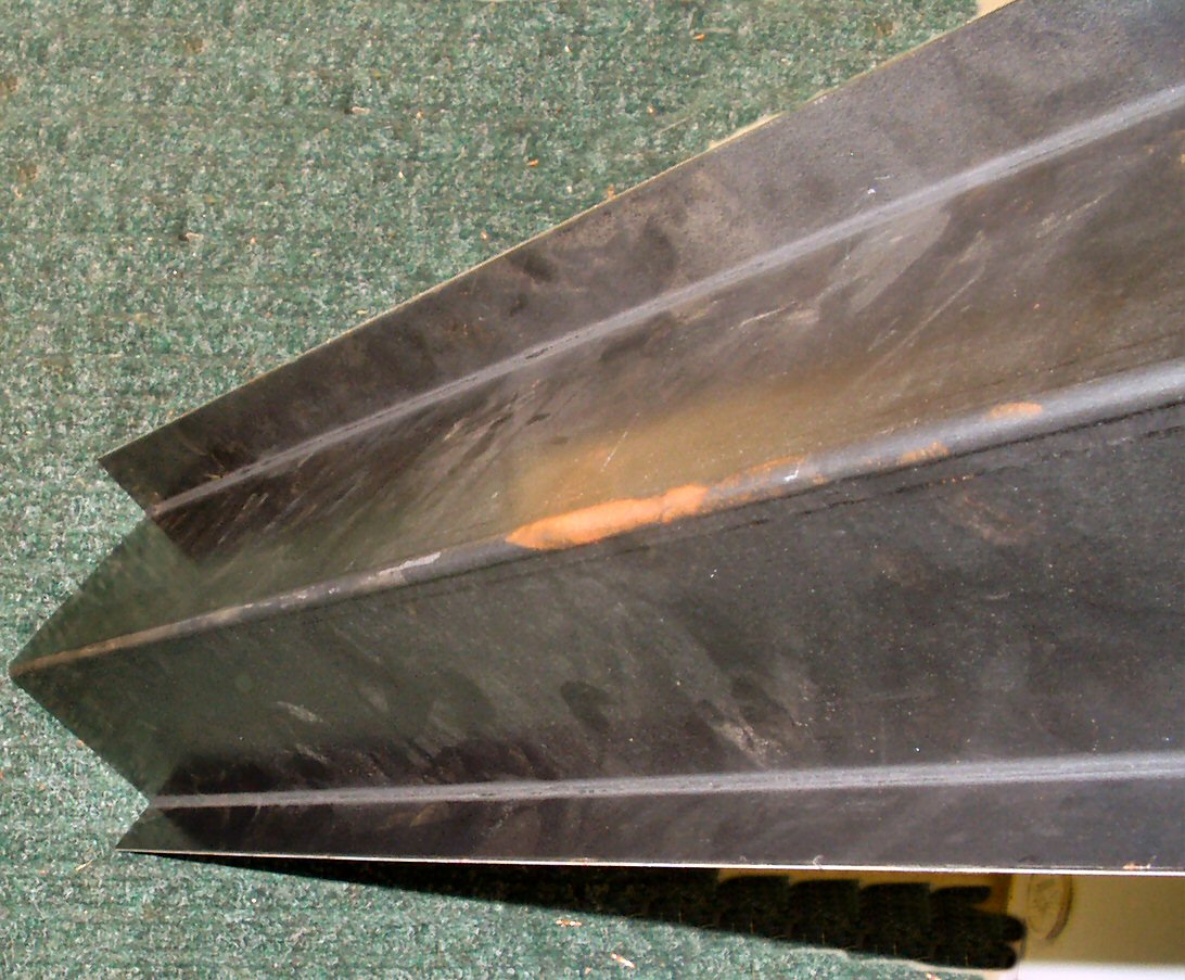
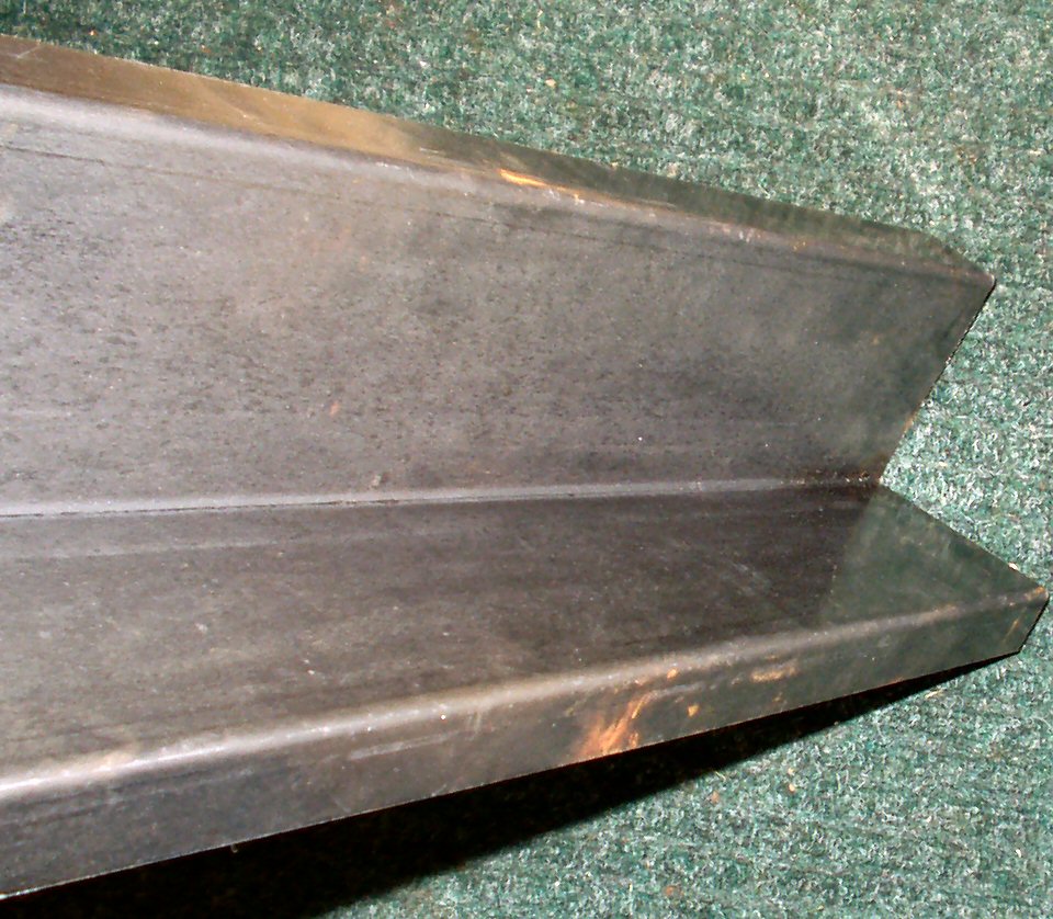
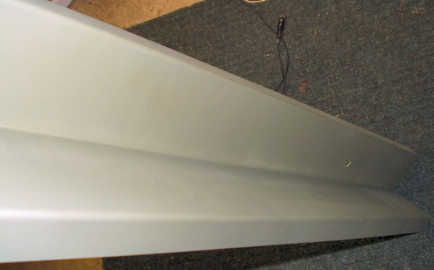
Fig. 27 Old Mid Bed Channel |
Fig. 28 New Mid Bed Channel |
Fig. 29 Outside View |
Fig. 30 Inside View |
Fig. 31 Primed |
Fig. 27 shows the sad shape of the old main channel. The new channel is 14 ga and does not have the curved hump for the rear power take off. I don't think this truck will ever have it so I won't bother trying to fab that one up. To mount this to the frame I am not using the method Toyota used. I will drill 1 3/8" diameter holes in the mid bed directly above the frame mounting bolts to enable a socket to be placed on the nuts inside the channel through the hole. I will use plastic push in plugs to fill the holes. This will also allow me to inspect the inside of the channel for rust. Figs. 28-31 Show the new channel.
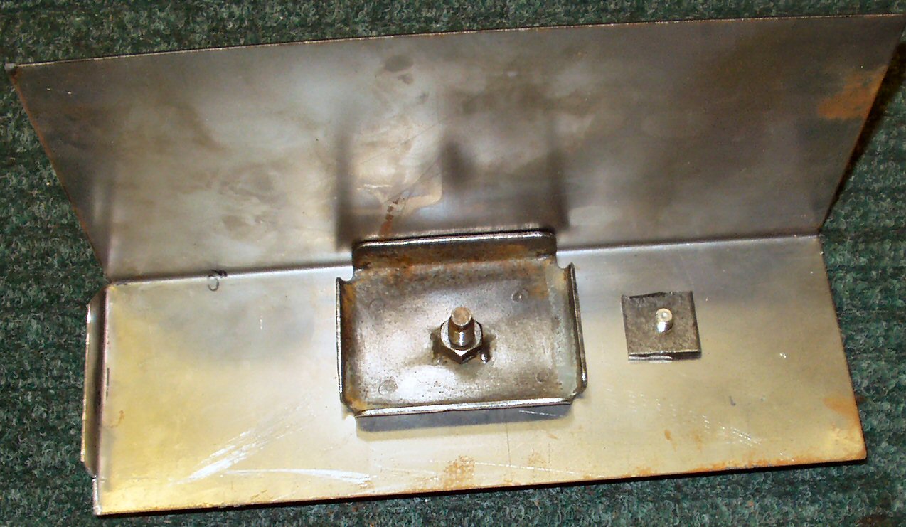
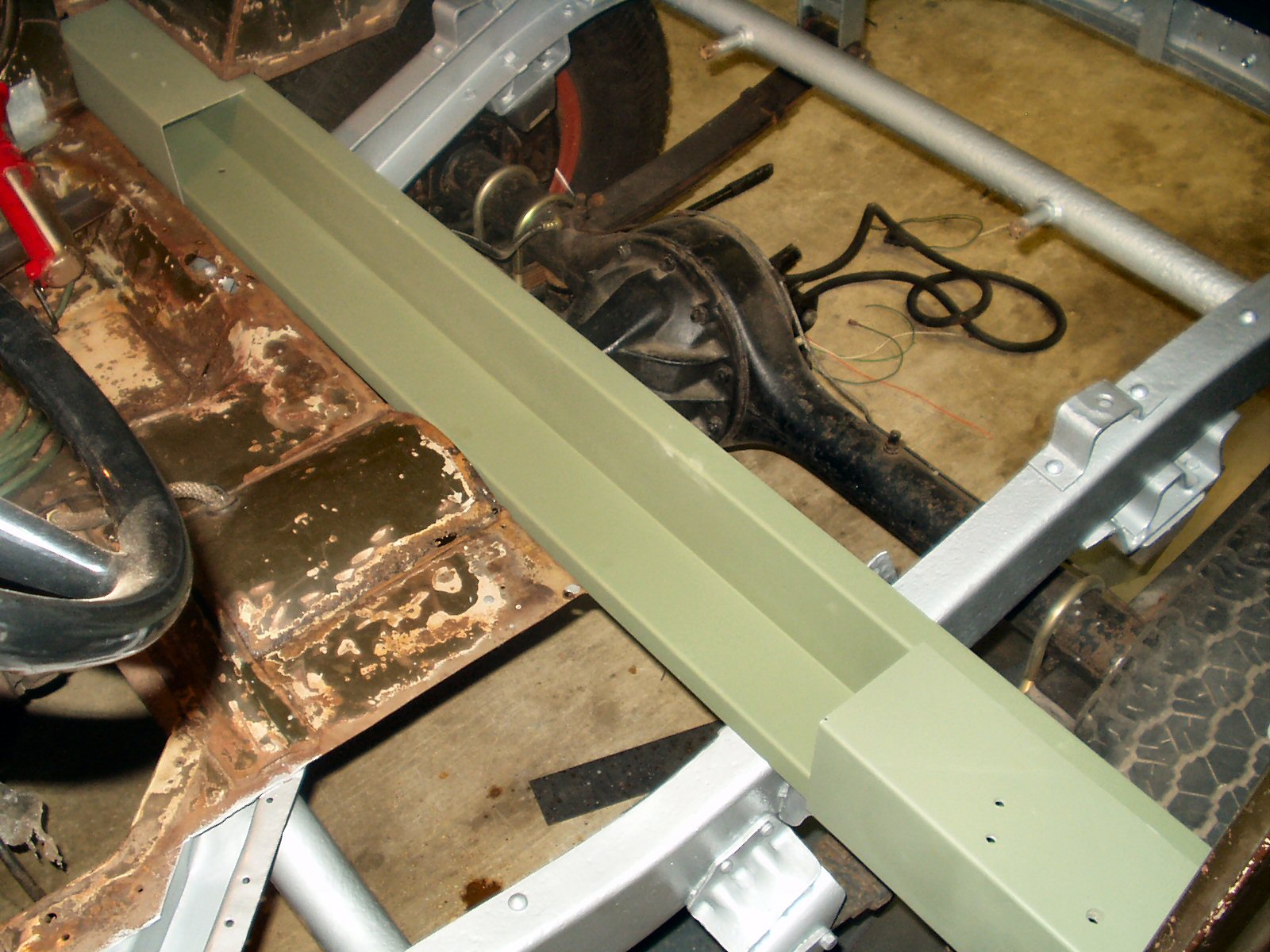
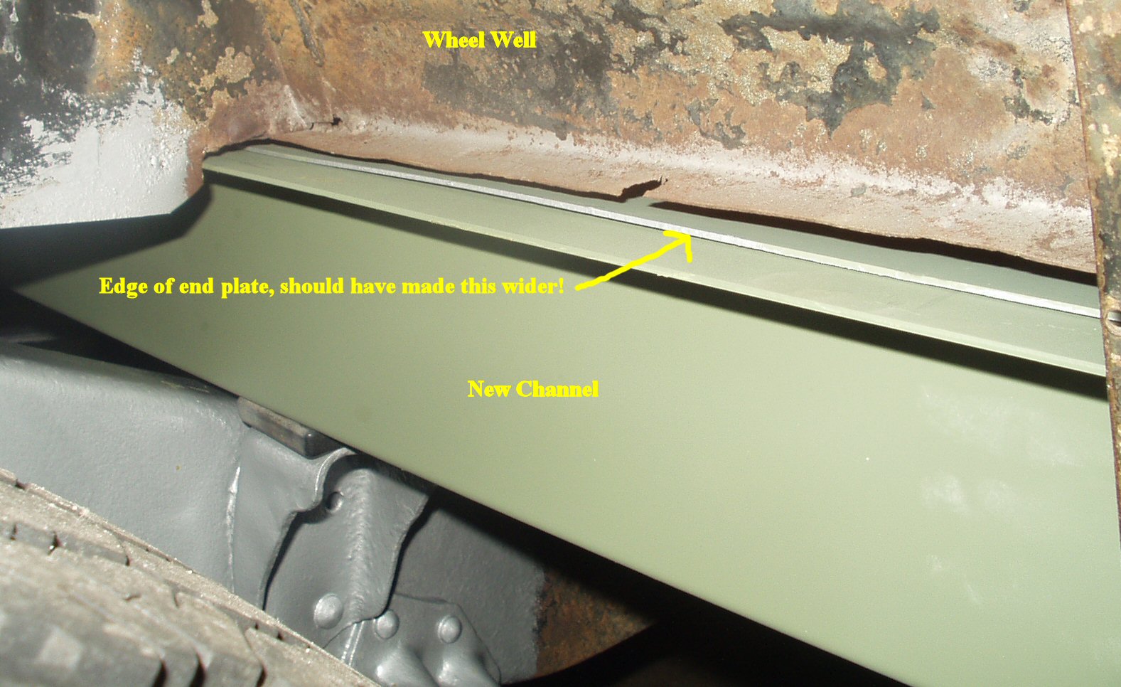
Fig. 33 Test Fitting Channel |
Fig. 34 More Fitting |
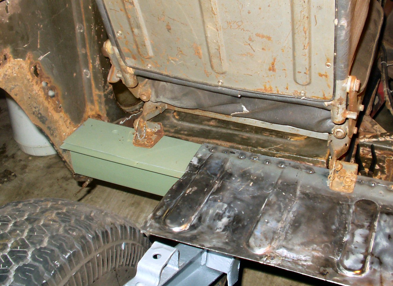
Fig. 35 Seat Still Bolts In! |
Fig. 36 Figuring out the mounting |
Fig. 37 Cutting Access Hole |
Fig. 38 Plug Welds |
6-18-2005. I finally got a bit of time to work on the channel some more. I got the frame coated with Rust Bullet and started test fitting the new channel. The only issue I had was this: when I made the back lip of the main channel wider I forgot to add that extra width to the width of the end pieces! See Fig. 34. It won't hurt anything but it just annoys me I forgot to do it. At this point I had to do some work on the floor pans. I'll come back here later to show the welding in place pics.
11-13-2005
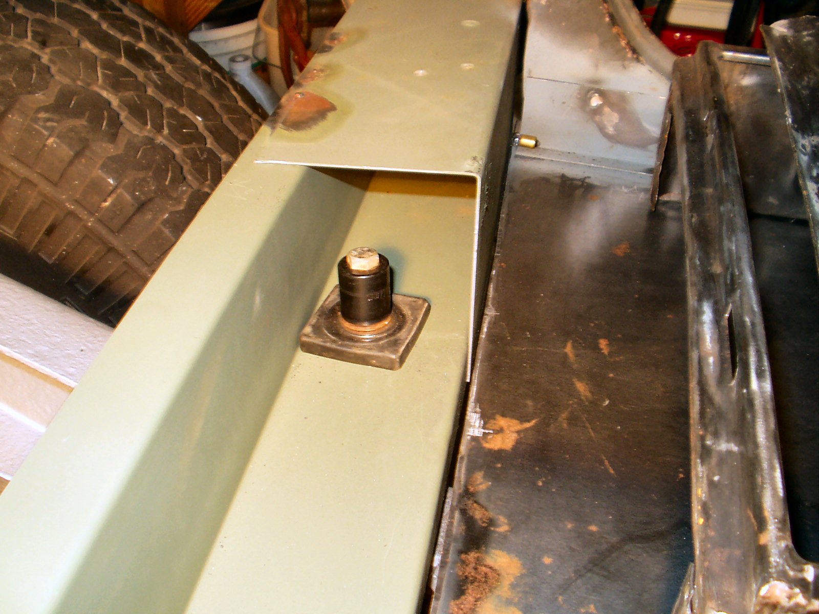
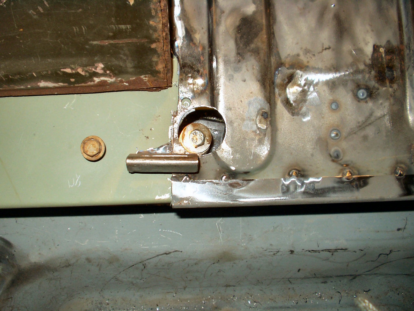
Yeah I know way too much time has passed... To ensure I had all the mounting plates for the seat welded in the correct location I had to sort of put it all back together. See Fig 35. It all fit great! I tack welded the end plates to the main channel then hooked up temporary mounts for the channel to frame. Yes that's an impact socket under the bolt... in Fig. 36. Next I positioned the mid bed in place, centered it, clamped it in place and took a measurment from the quarter panel to the center of the bolt. (12.5") I used a 1 3/8" hole saw cut through the mid bed and part of the end plate. See Fig. 37. I used that particular size because I could get plugs that size. Satisfied that everything was still lined up I welded the mid bed section to the center channel using plug welds across the bottom and top. See Fig. 38. I'll use a good seam sealer to seal all these seams when I'm done welding on them.
Hosted by Global Software, Inc.
©1998 - 2023 Mark C. Baker Web Designer
Please: No part of this web site may be used without express permission... email mbaker@globalsoftware-inc.com for permission.