While working on the rear channel replacement I
got tired of having to reach up inside the truck to open the rear hatch due
to the handle being broken. So I posted on the LCML to see what folks had done
to fix it. I got several responses ranging from: "Bend over and pay CCOT
$54" to, "Well I rigged up a T-handle thingy" I liked the T-handle
idea since that was what was on the inside. I figured I would take it apart,
look at the problem and see if I could come up with how they did it. If nothing
else I would remove the broken handle and bend over for CCOT!
I took the rear hatch access panel out from the
inside and saw the piece of broken handle lying in the bottom of the door. After
removing the broken handle I immediately saw why they break so easily: The handle
is made from cast POT metal and has a built in point of failure! It breaks because
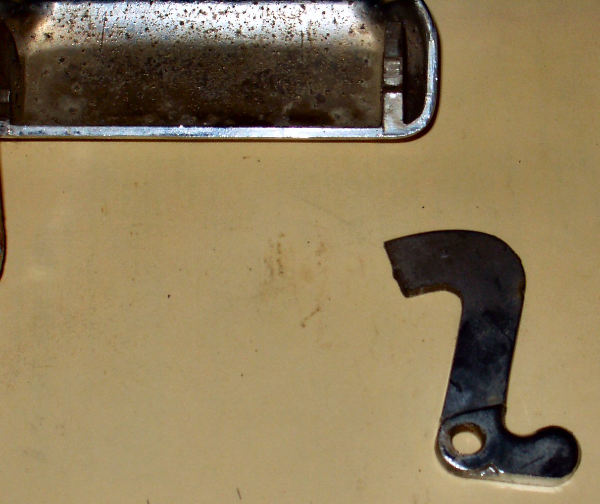
a notch is cut into the right hand side for the tail gate lock to engage. This
makes that area half the width of the other side therefore it snaps. See Fig.
1 for the broken piece.
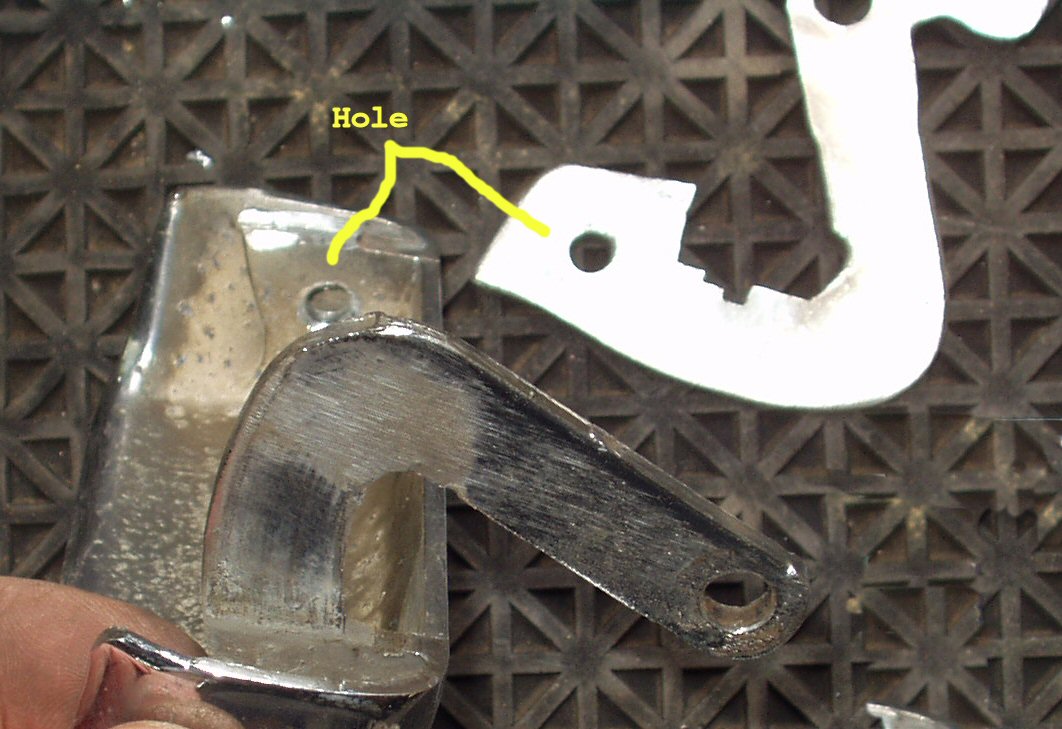
Fig. 1
Broken Handle
Fig. 2
Making Lock Notch
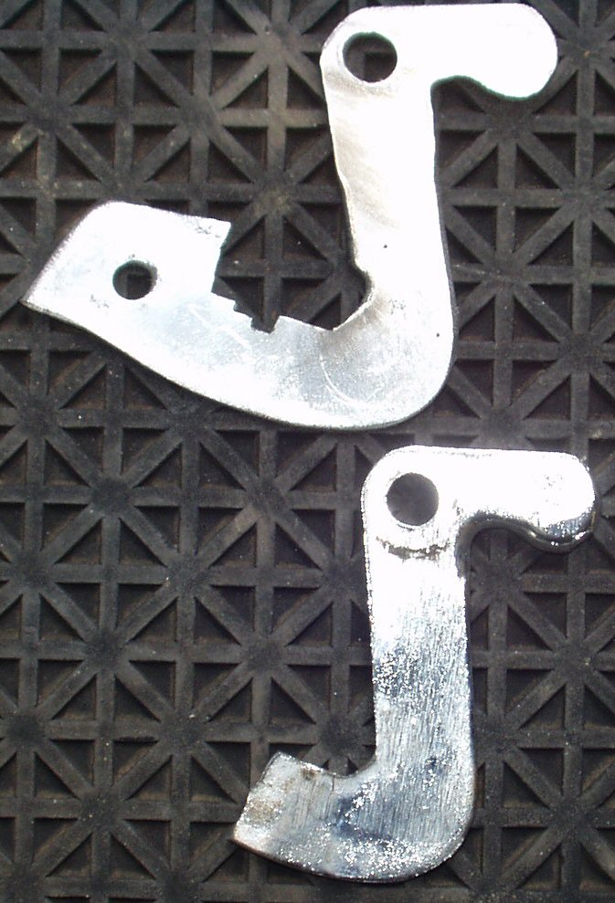
Fig. 3
New and Old
Since you can't weld pot metal, I had no T-handle to use, and
I didn't really want to bend over, I decided to spend that rainy Saturday
coming up with a new way to fix the handle.
I started by removing the lock and taking the handle mechanism
apart. This is easy to do. Once I had the handle out I saw exactly how I was
going to fix it. I would make a new replacement piece from 10 ga galvanized
sheet metal using the broken piece as a guide. I started by making a thick paper
template of the broken piece out of a file folder. I traced the broken piece
out then made another piece that matched the base of the broken piece still
in the handle. I taped these together, laid them on a piece of 10ga sheet metal
and used a jig saw with a metal cutting blade to rough cut it out. Next I clamped
the old piece to the new piece with some mini c-clamps and used a grinder and
a file to give it its final shape. While still clamped together I drilled the
pivot hole.
Now I made sure the piece would fit into the opening. I had
to do a bit of grinding but not much. I re-installed the lock and once it was
there I marked the place to make the cut in the piece for the lock mechanism
to engage. I used a Dremel tool with a cut-off wheel to do that. See Fig.
2.
Now that I had a functional piece it was time to mount it to
the handle. I first thought I could use JB Weld to attach it but after looking
at it I decided to just drill a single hole through the remaining piece in the
handle and use a small bolt. The only way I was able to drill the hole was to
use a small air powered, right angle drill. You could probably also use a Dremel
tool. See Fig. 4-5.
Fig. 4
Drilling Hole
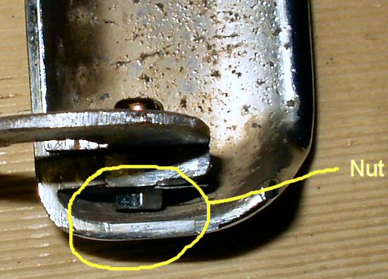
Fig. 5
Attaching handle
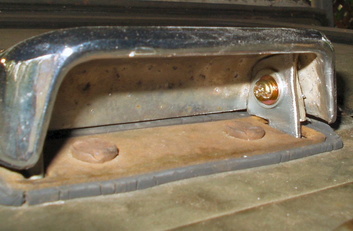
Fig. 6
Handle Attached
The Easy Way to Making Your Own Part
I got to thinking that someone else might want to do this and
save the $54 that CCOT wants for this part so I took my handle apart one more
time and using graph paper I traced around the finished piece. I then scanned
the drawing in at 1:1 and printed the result to ensure it was the exact same
scale, it was. Click the pic in Fig. 7. This will
open a full size version of the scanned template. Right click on the pic and
save it to your hard drive. When you print it out make SURE you print at 1:1!
If you try to scale it it will be the wrong size. The scanned image is an 8.5"
x 11" sheet.
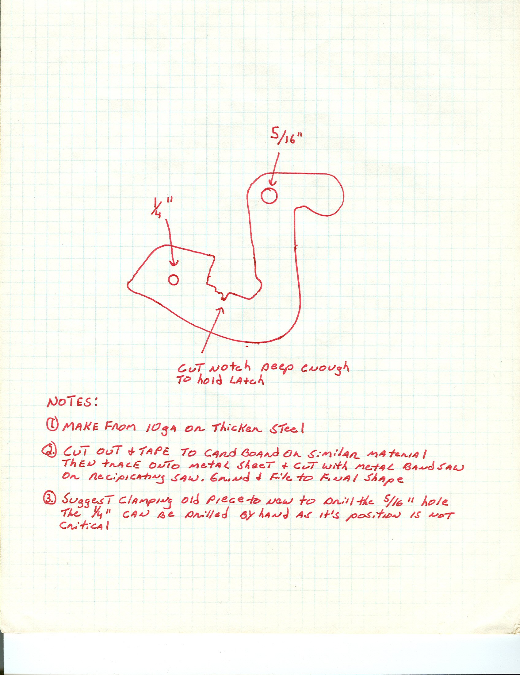
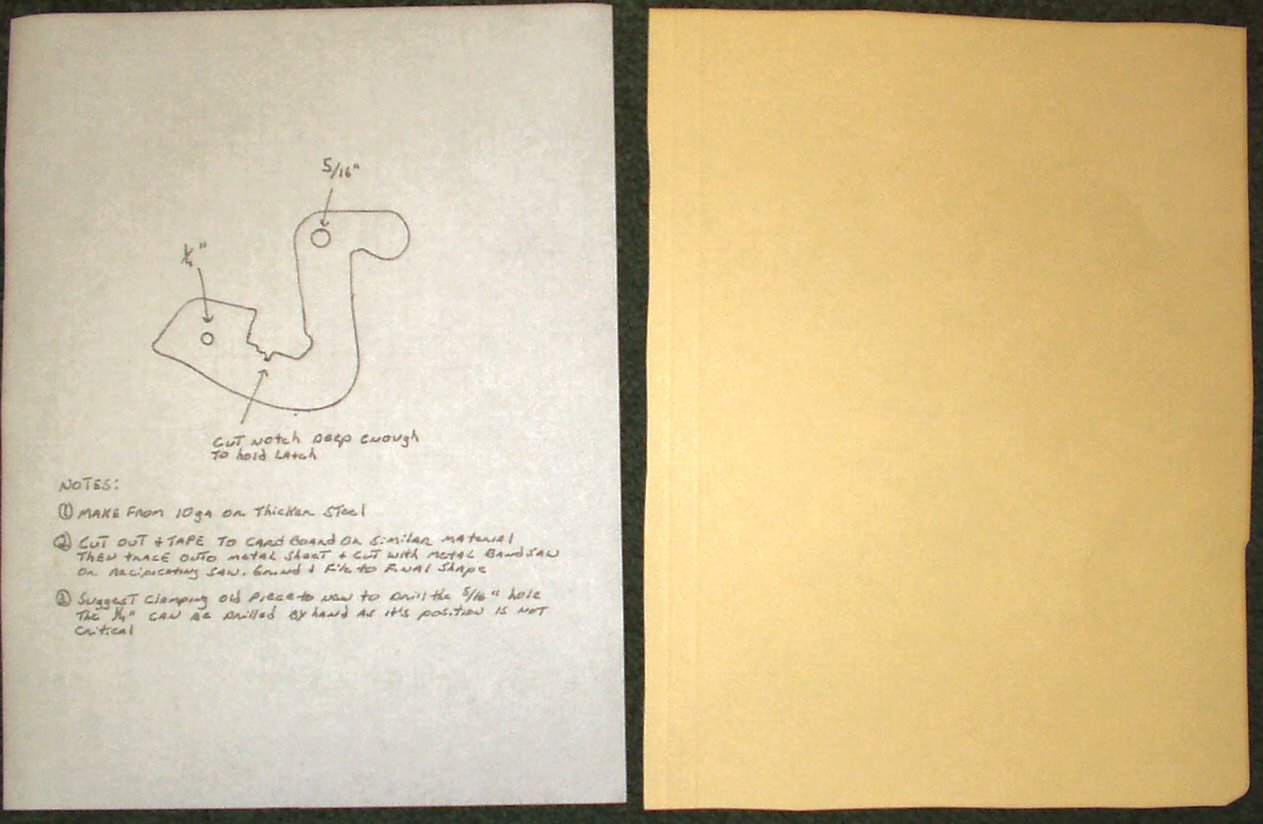
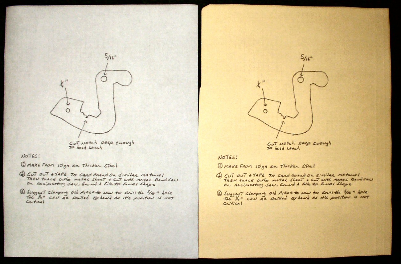
Fig. 7
Template for part
When you print the template print it on as thick
a material as your printer will handle. Card stock is fine or do what I did
, cut a file folder up to an 8.5 x 11 piece and print on that. See Figs.
8-10.
Use scissors or a good sharp razor and cut the
template out. You don't have to be super exact but the closer you get the less
you have to grind later. Lay the template on the piece of steel you selected
and trace around it with a pencil or sharp point permanent marker. Take some
clear packing tape and cover the outline to prevent it from smearing. Use a
jig saw with a metal blade and cut the template out. Now drill the holes and
start test fitting. Use a file and grinder to make it fit. See above about drilling
the hole in the handle.