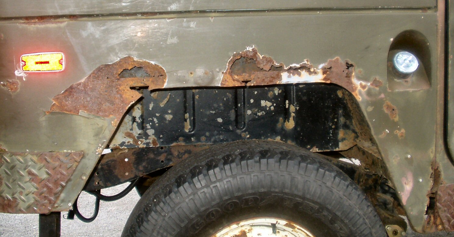
While I was waiting for the bed panel to be made by my local
sheet metal shop and the wheel well tops to arrive I removed the fuel filler
panel for use on the new panel.
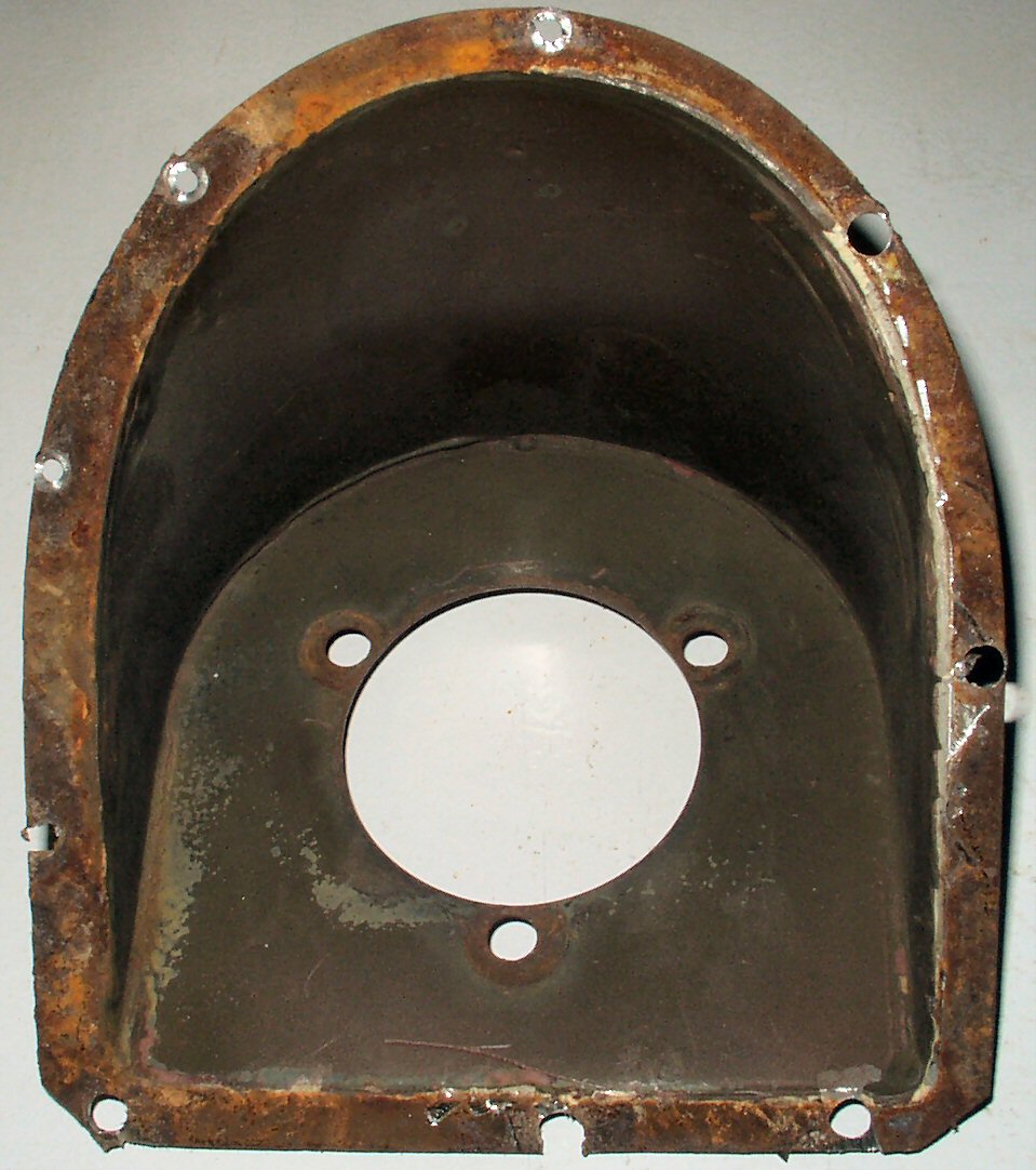
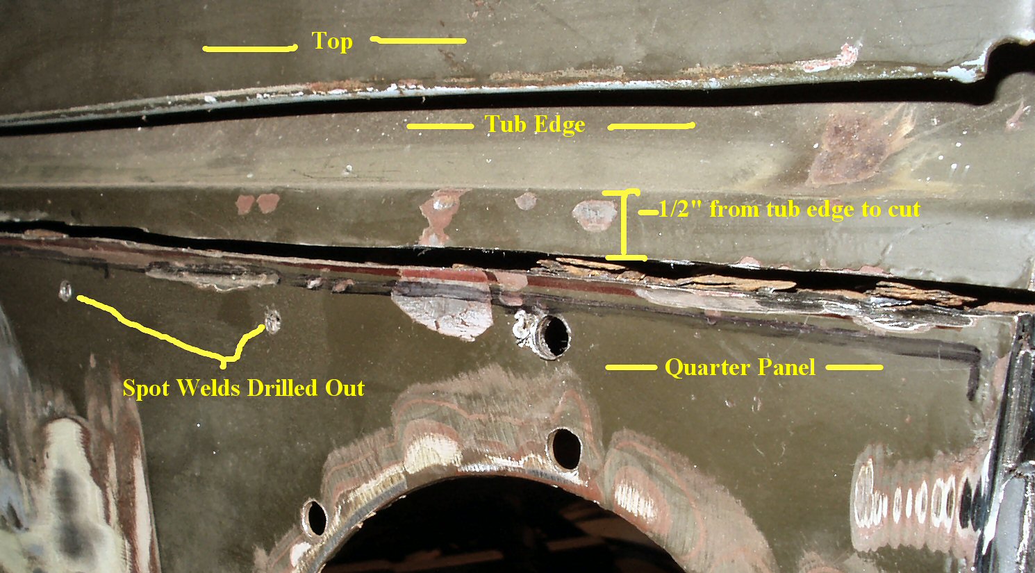
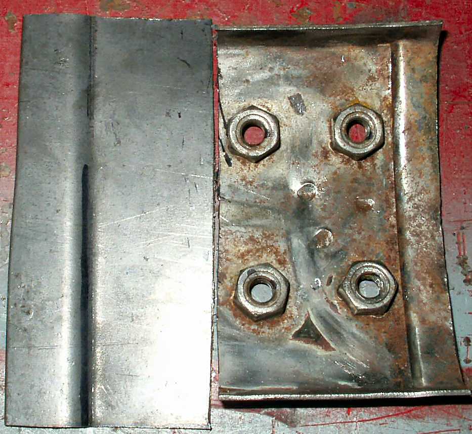
Fig. 1 shows the panel
before I started. You can see a couple of the spot weld 'dimples' that need
to be drilled out.
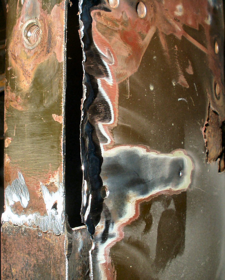
I used a sharp 1/8" drill bit and drilled out the center
of the spot weld all the way through the fuel filler panel and the quarter
panel. You will need to drill some from the inside and some from the outside
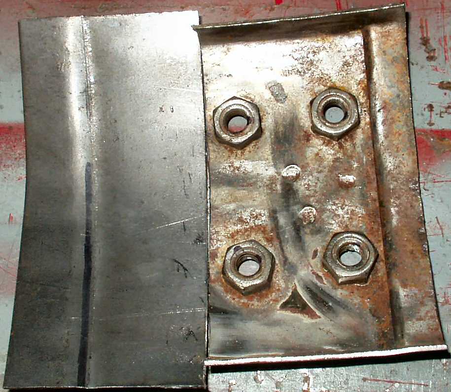
depending on how visible they are. Next I used a 1/4" drill from the
outside and drilled until the panel popped apart. See Fig.
2.
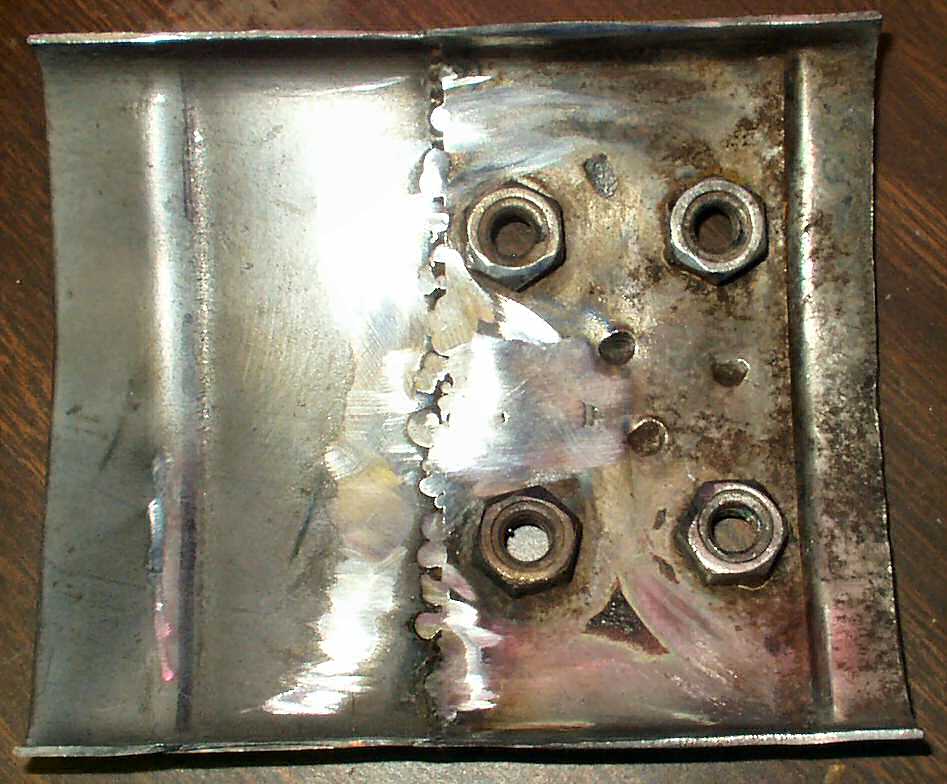
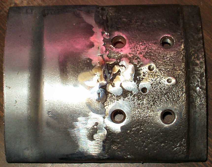
Sometimes I had to drill all the way through and use a sharpened
putty knife to finish cutting the rest of the weld. The sharpened blade also
helped to cut through the body putty that seals the seam. See Fig.
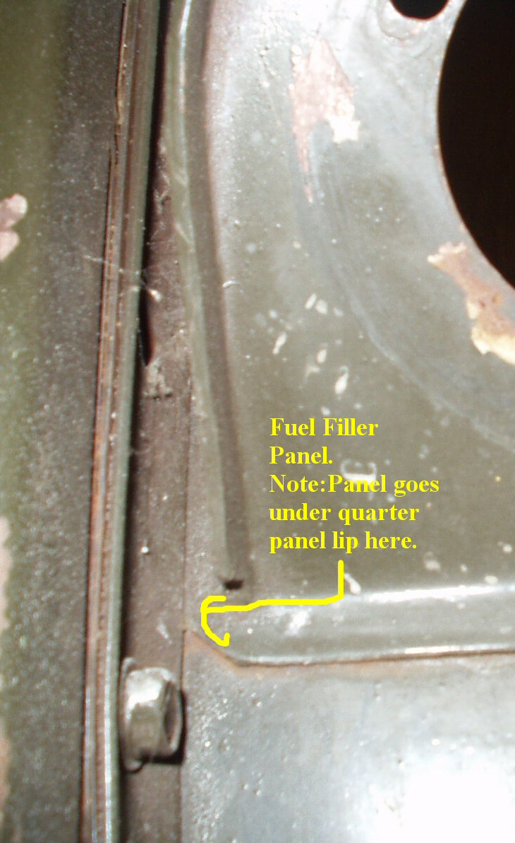
3-4. . Note: There is one spot weld for the filler
panel under the lip where the quarter panel bolts to the door jamb. You will
need to remove all the bolts from the quarter panel lip so the fuel filler
panel will slip out. See Fig. 5.
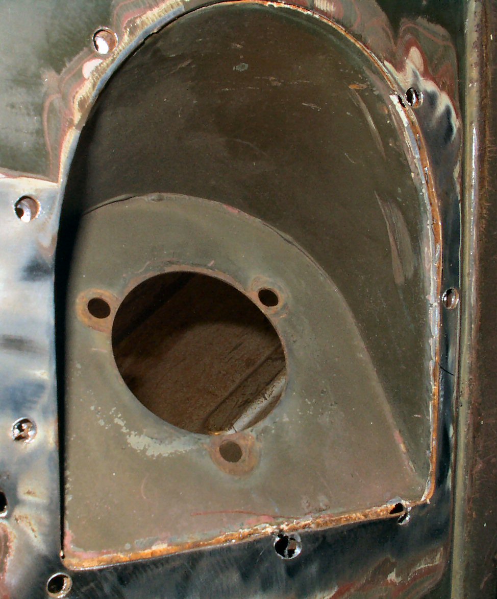
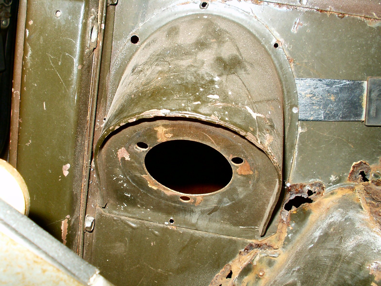
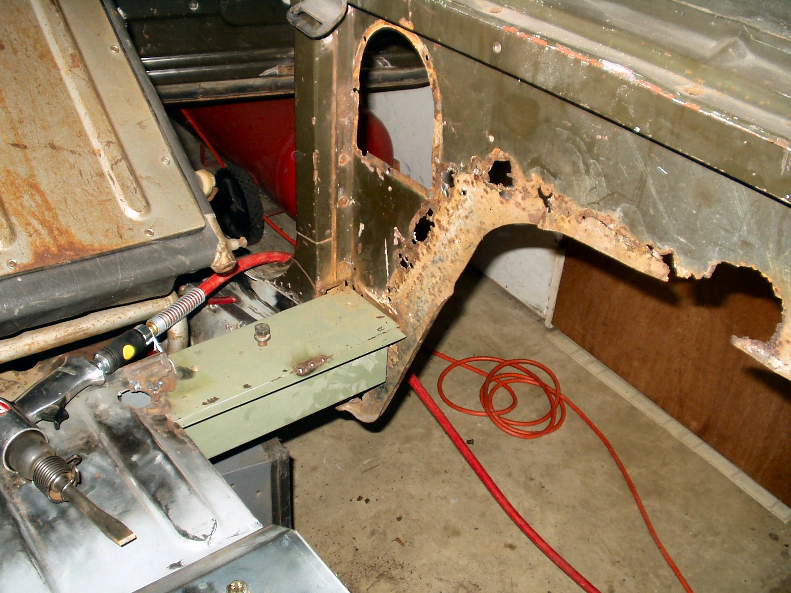
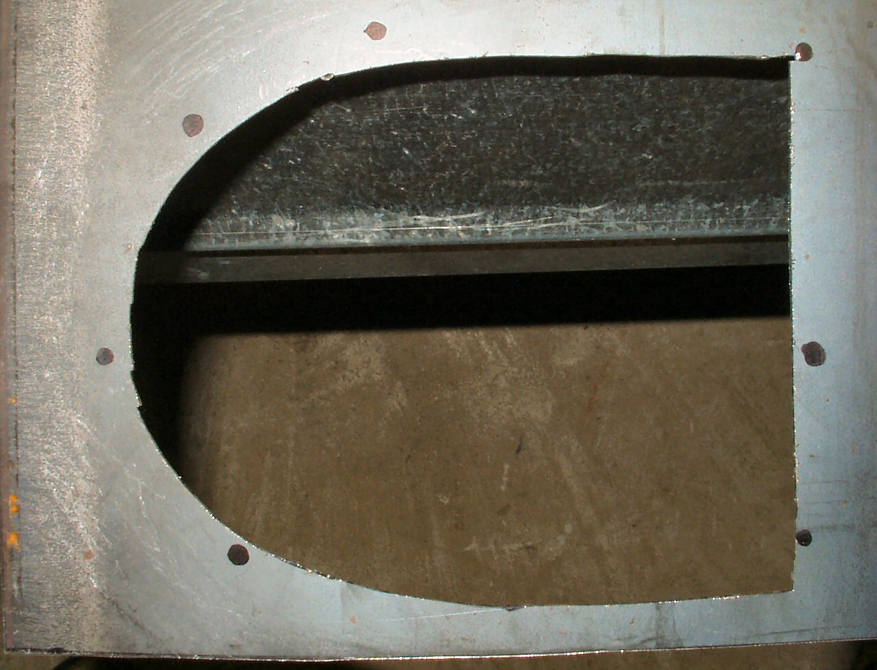
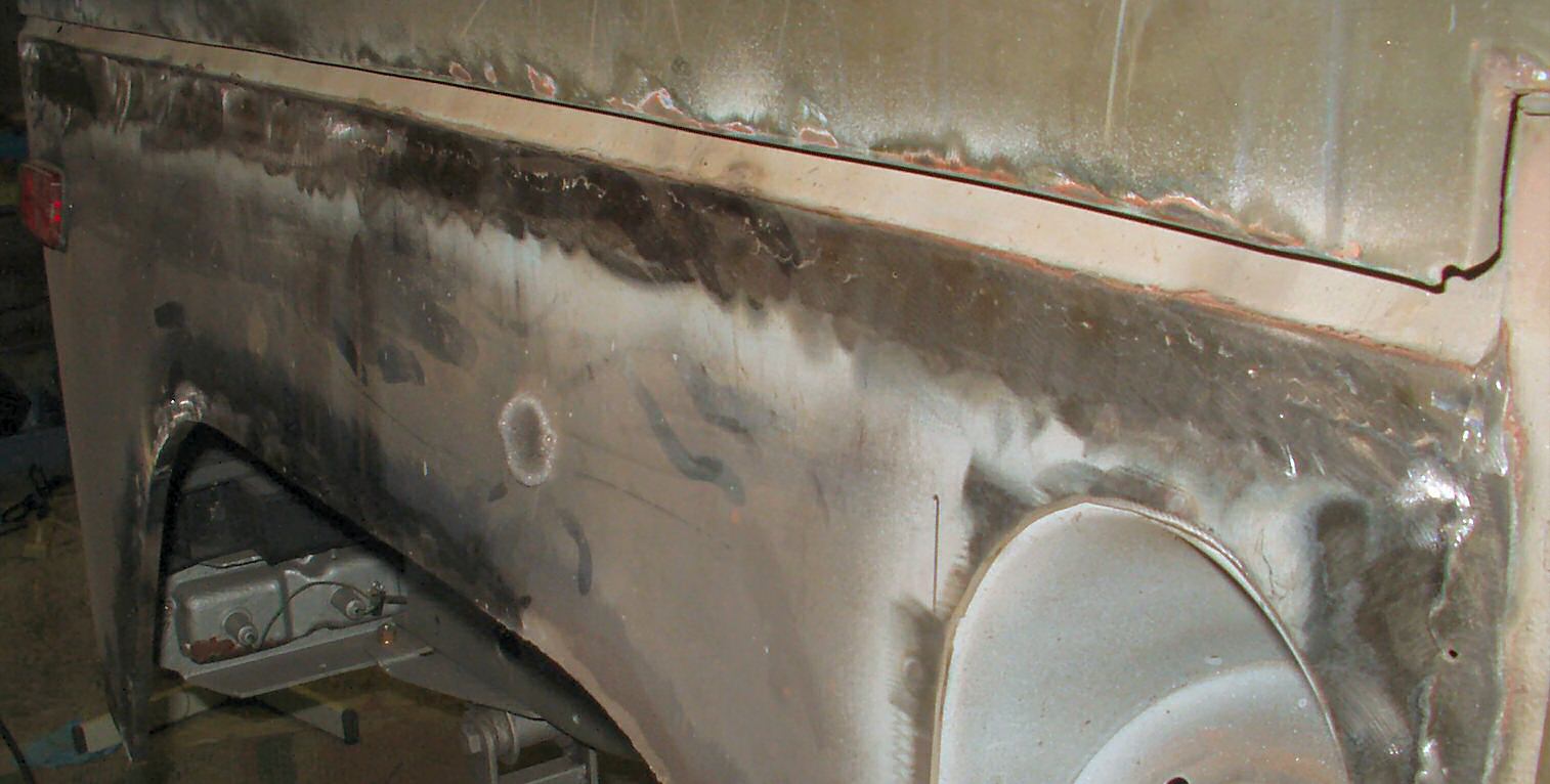
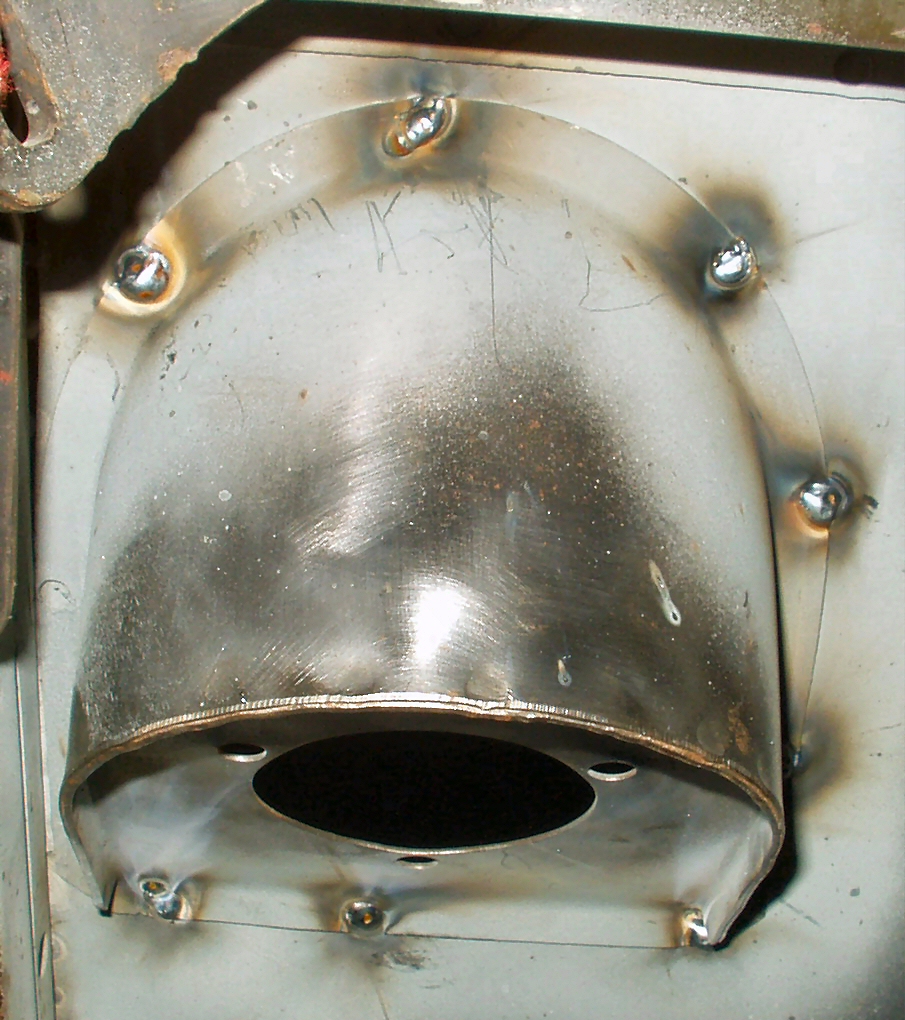
Fig. 6 shows the hole
where the panel was. Once the old quarter is removed I will use this hole
as a template to mark the new panel.
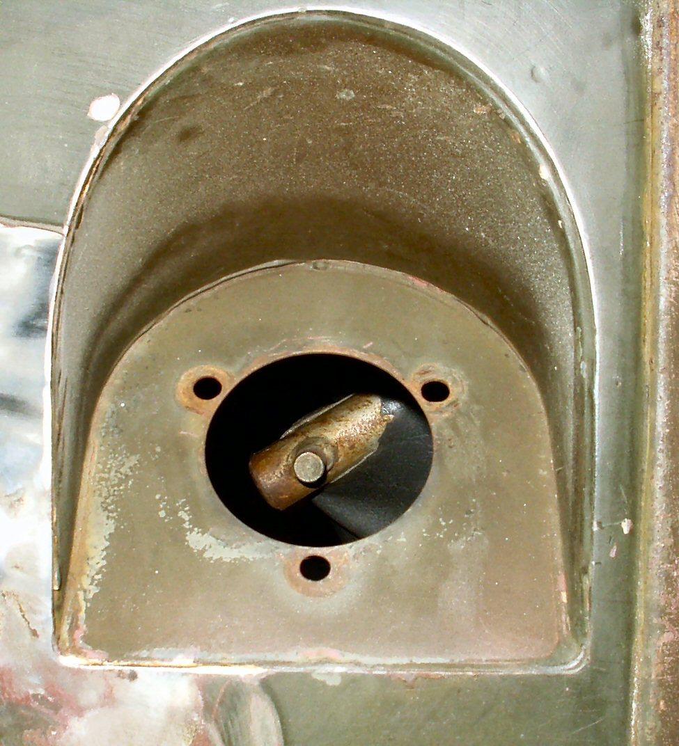
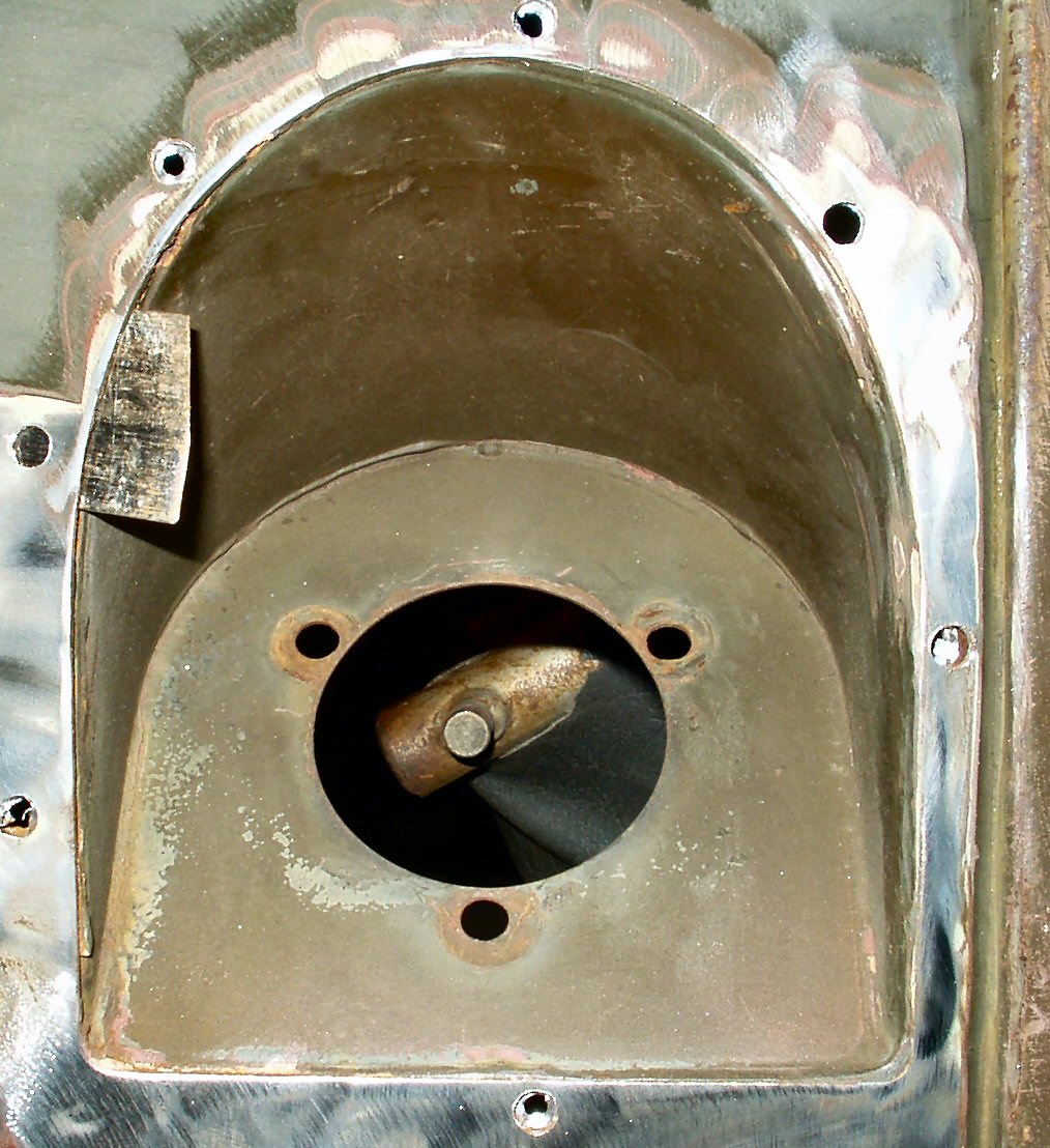
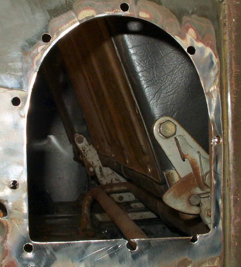
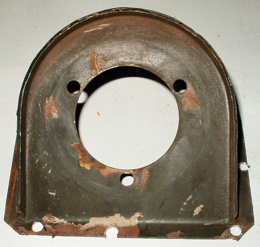
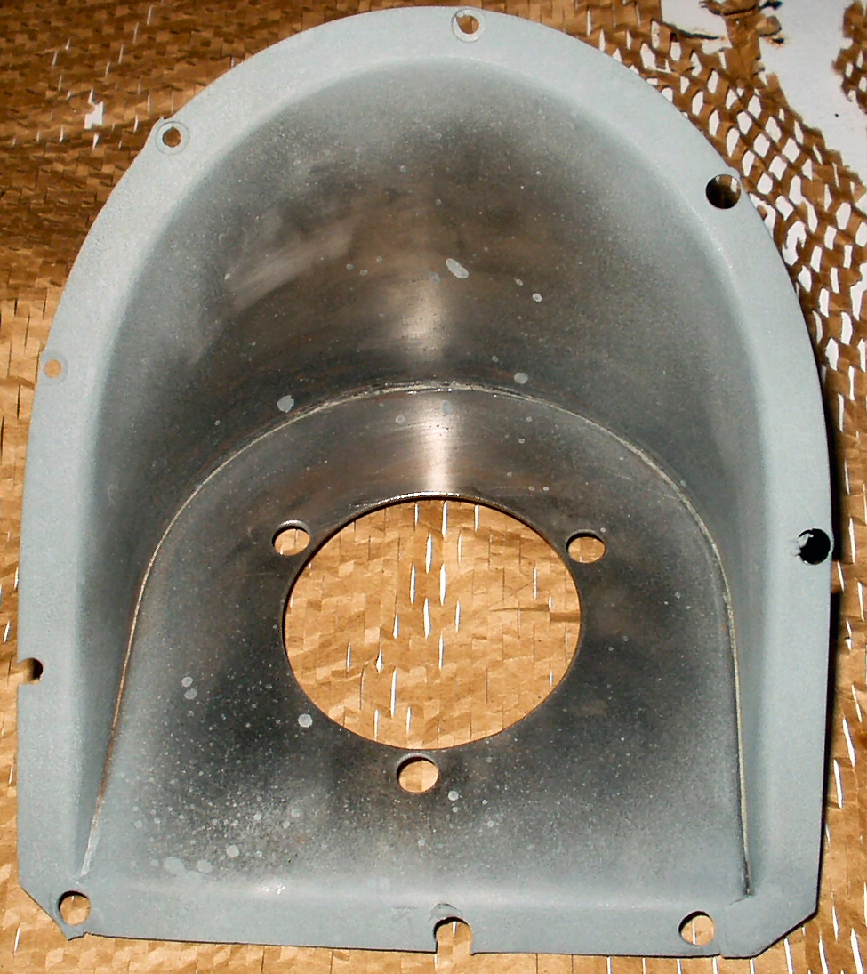
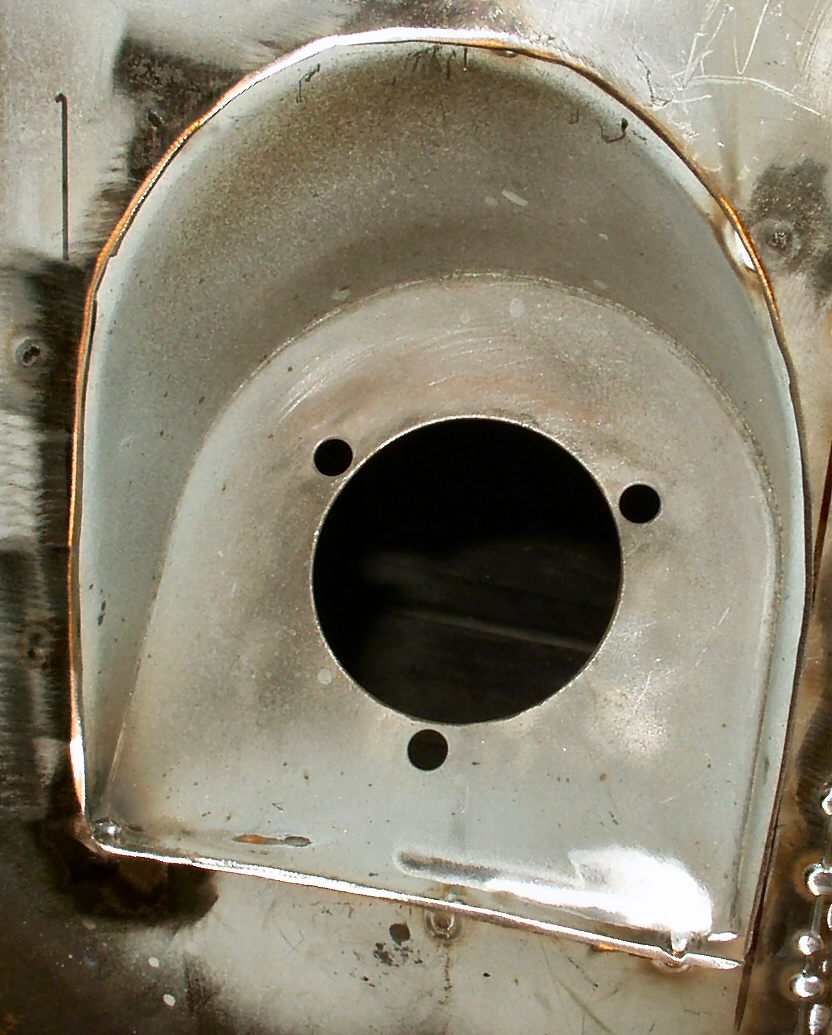
Once I had the fuel filler panel removed
I took a couple of pics (See Fig. 7-8) then placed
it in the de-rust tank. Once out of the tank
it will be repaired, primed, and welded back into the new quarter panel.
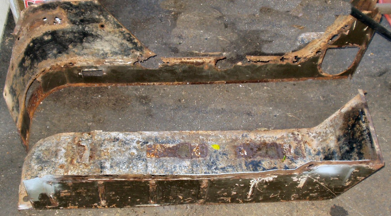
Fig. 8
Removed Wheel Well
Fig. 9
Quarter Panel Front
Fig. 10
Quarter Panel Rear
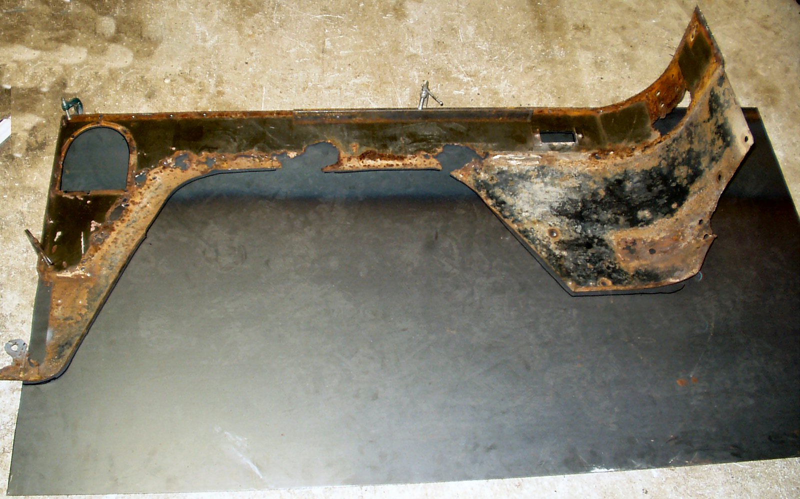
I drilled out the spot welds holding the wheel well in place
and set it aside for further disassembly. I will be reusing the side of the
wheel well but not the top. Fig. 9,10 show what's
left of the quarter.
Fig. 11
Fitting it all together
Fig. 12
The SEAM
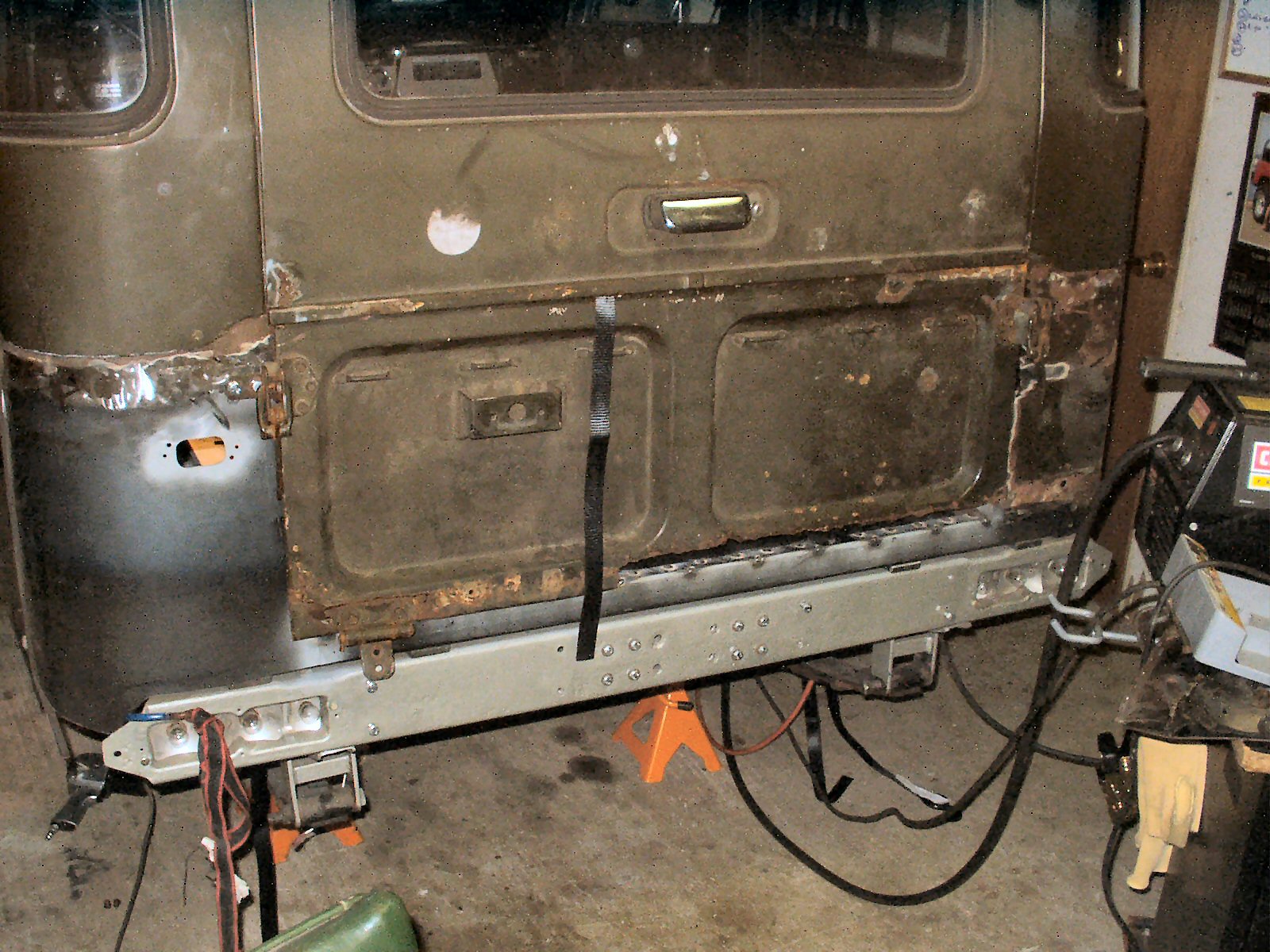
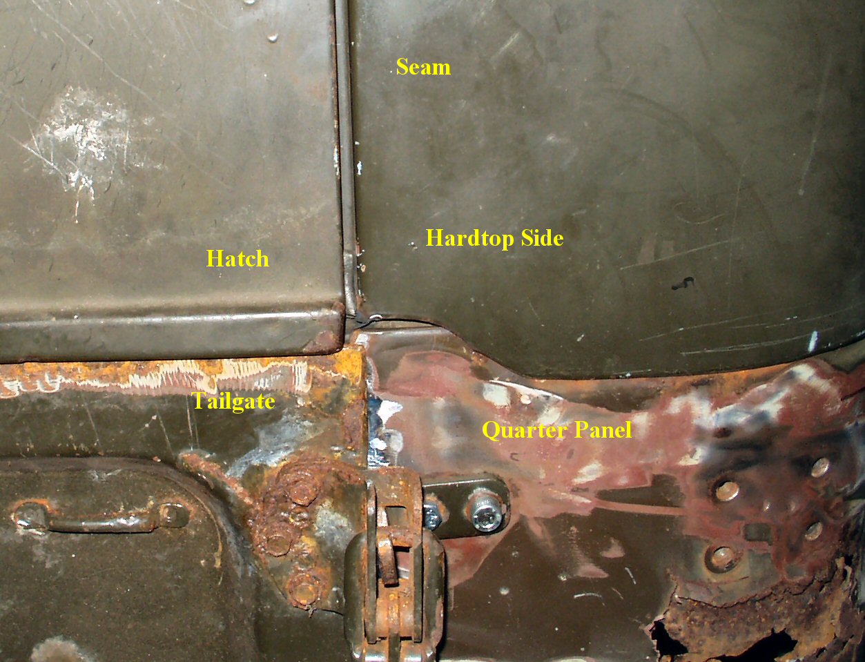
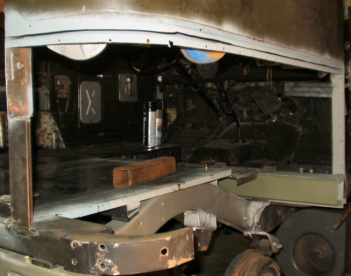
Since this panel was the last panel to be removed/installed
I realized I needed to make sure all my body panels and doors were going to
line up properly. I put the tailgate back on and closed the rear hatch. See
Fig. 11. Hmmm... A perfect gap on the left hatch/tailgate!
Hmmmm a LARGE gap on the right. I looked and looked at how everything was put
together and realized that the entire passenger side quarter and hardtop section
were tilted. The quarter was tipped down, and the hard top side; out at the
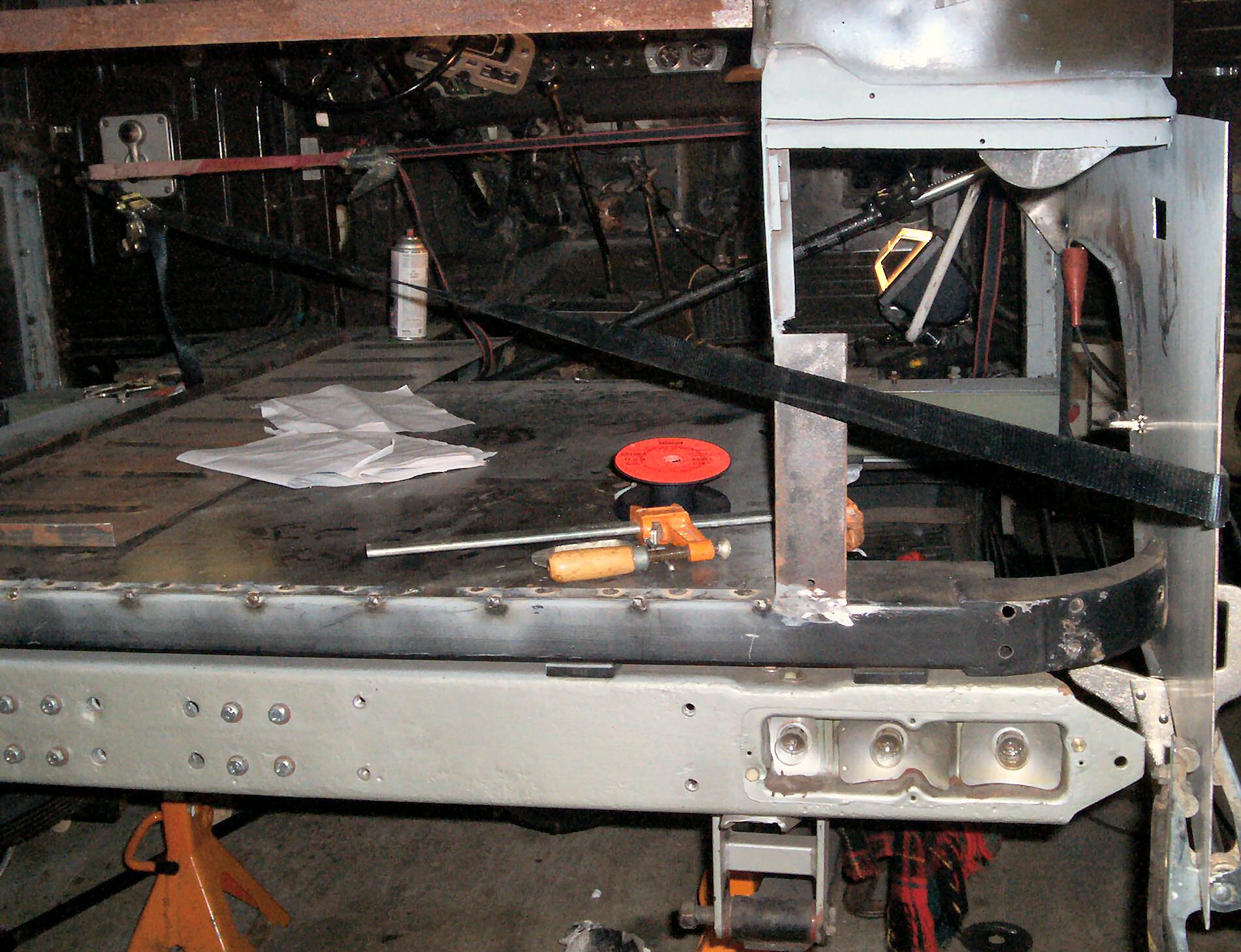
bottom. I used a ratchet strap to pull them back into alignment. See Fig.
12. I then welded on a brace to hold the alignment while I installed
the new quarter panel.
Fig.13
Spot Welds
Fig. 14
Tire Carrier Backing Plate
Fig. 15
Freeing Quarter Edge
Fig. 16
Cutting From Tub
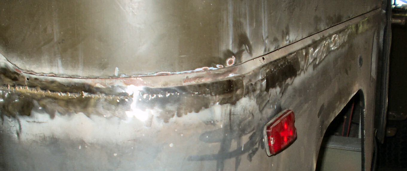
Next up is drilling out all the spot welds holding the old quarter
panel to the tub. Like we did on the drivers side use a 1/8" drill first
then come back with the 1/4" drill. See Fig. 13.
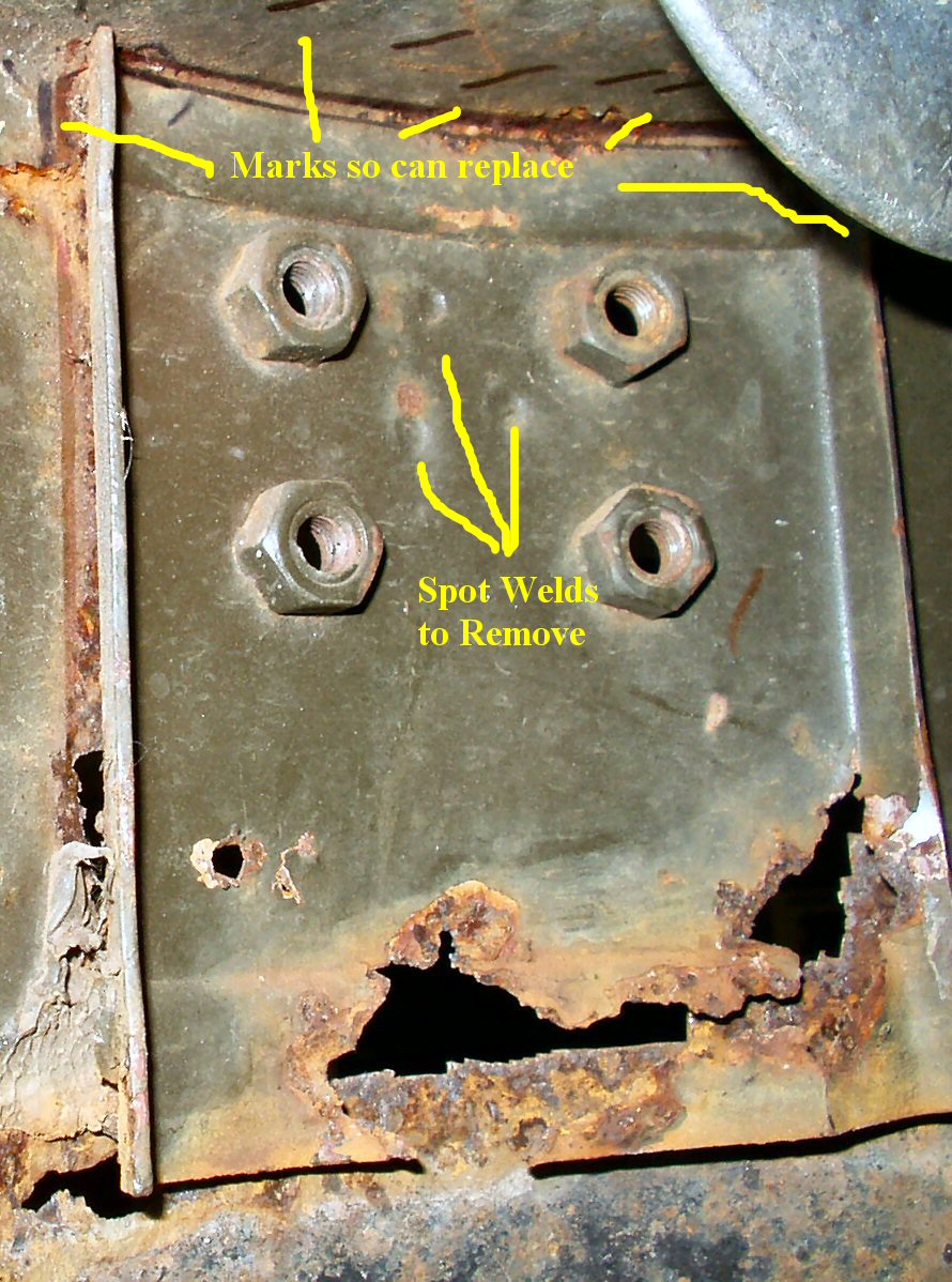
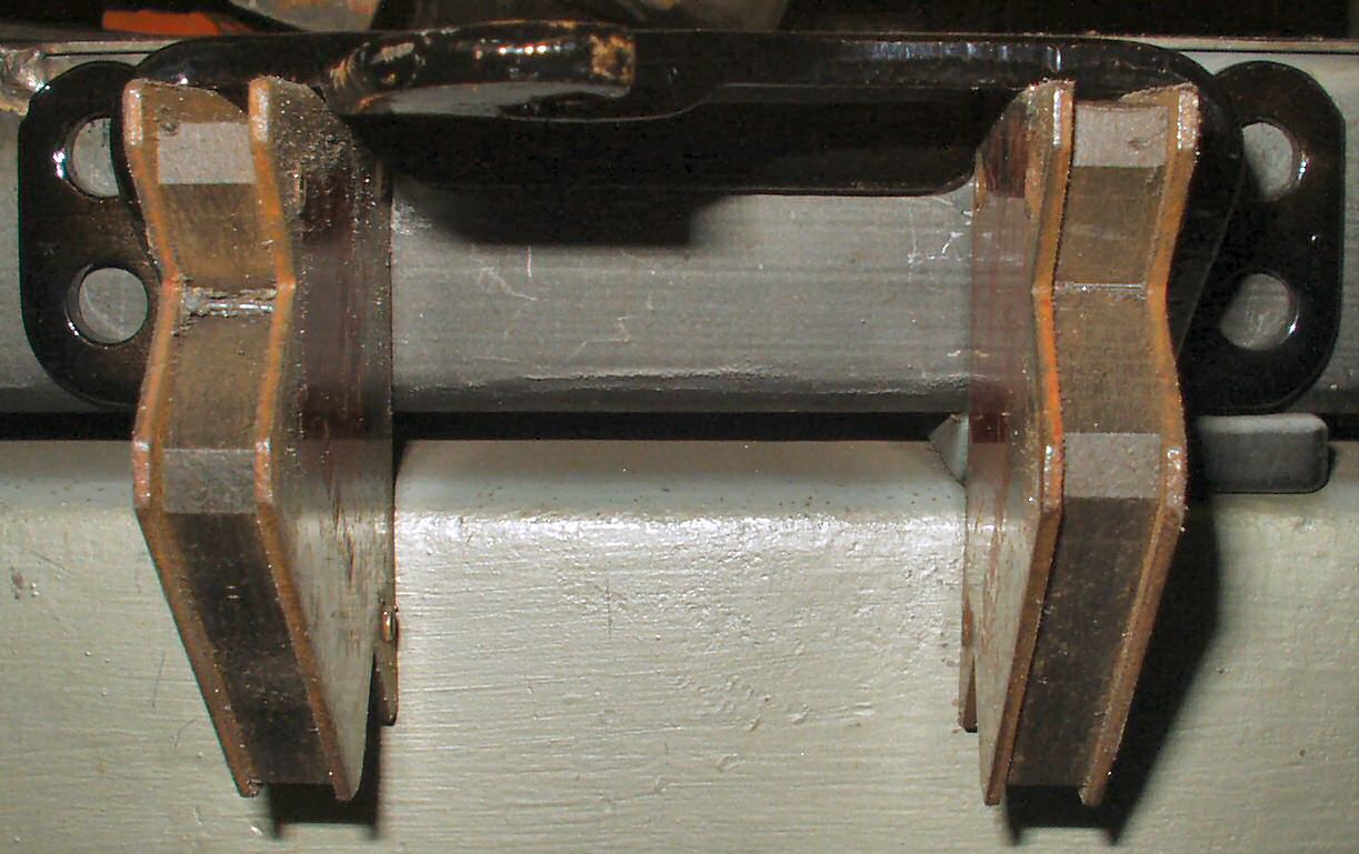
I thought that the spare tire carrier backing plate was covering
up some spot welds but it turns out it is spot welded ONLY to the quarter panel
not the tub rail. There are three spot welds that must be removed then it just
falls off. Before you remove it however make sure to mark it's location on the
tub rail! Otherwise it will be hard to get it aligned back up! See Fig.
14 for the marks and spot welds.
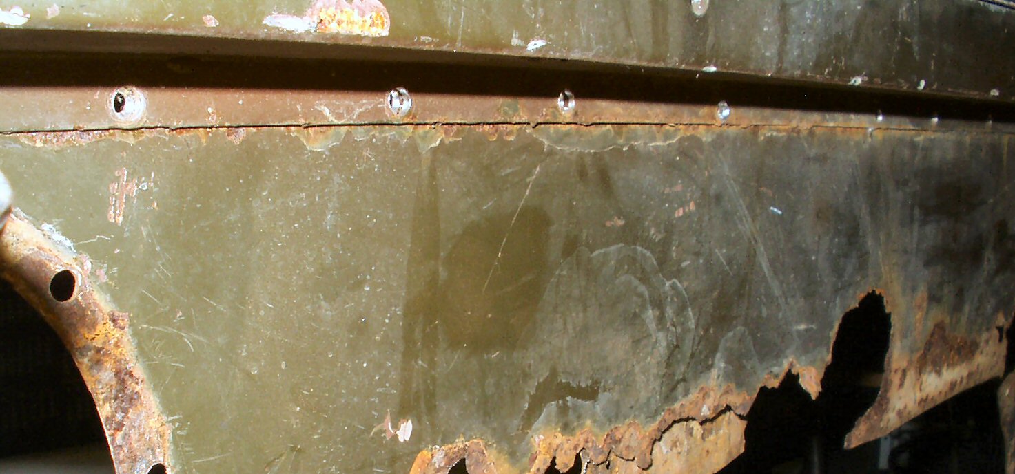
Now use an aggressive grinding wheel and where the quarter attaches
to the corner support (where tailgate or door frame is) grind till the edge
is loose. See Fig. 15. Ok now we have the front
edge loose by removing the bolts (See Fig. 5 above)
and the rear edge loose by grinding it off. Now we need to mark for the long
cut to separate the panel from the tub rail.
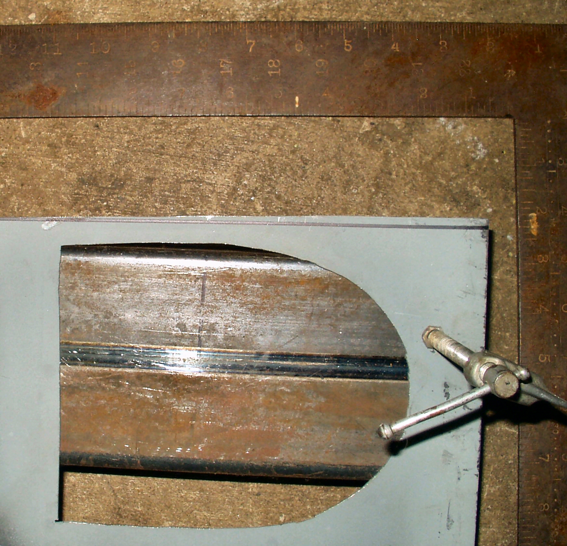
Get a carpenters square and set it for 1". Lay the square
against the tub rail. Use a Sharpie pen and starting at the front draw a line
along the quarter and around the curve until you run out of ledge. Now you will
need to transfer the line on around the curve. I used a flexible metal ruler
but any flexible material with a square edge and about 14" long will work.
Lay it along the existing line then bend it around the curve. Now have a helper
transfer the line on around to the edge.
Get your cut off tool and mount a 1/8" or .40mm wheel in
it. Get your ear plugs, face shield and particle mask on. Wear gloves. Start
at the front and while keeping the wheel level with the line start a plunge
cut. Once you have penetrated the metal then start moving the tool forward and
backward a bit all while keeping it level with the line! This takes a bit of
practice but once you get the rhythm of the tool you will be amazed at how fast
this will cut sheet metal! See Fig. 16 for my cut.
(Note that I screwed up and had my square set at 1/2" and exposed the tub
channel. This means that I will not have the channel lip acting as a heat sink
but instead will have the edges of both panels to weld together in open air.
This is going to result in a lot of edge burn off. :-( I may tack weld a backer
plate in.)
Fig. 16
Laying out New Quarter
Fig. 17
Filling in lines
Fig. 18
First Cut
Fig. 19
Fuel Filler Opening
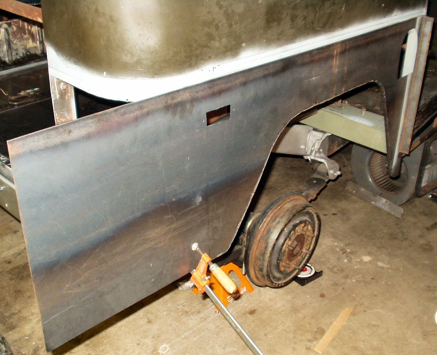
Ok the old panel is off in one piece so lets
make a new one!
Lay the new 16 ga sheet on the floor
on top of some spacers and clamp the old panel to the new sheet. See Fig.
16. Make sure to use an edge that was machine cut so you KNOW it is
a square edge!
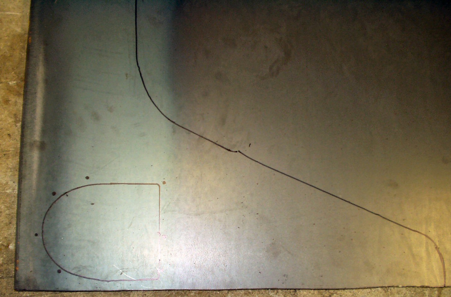
After making sure it is aligned properly use a Sharpie and
mark along the edges till you get to the curved section. If your panel is
rusted badly like mine then where you have no metal to act as a guide just
leave it blank. We will fill in the lines later.
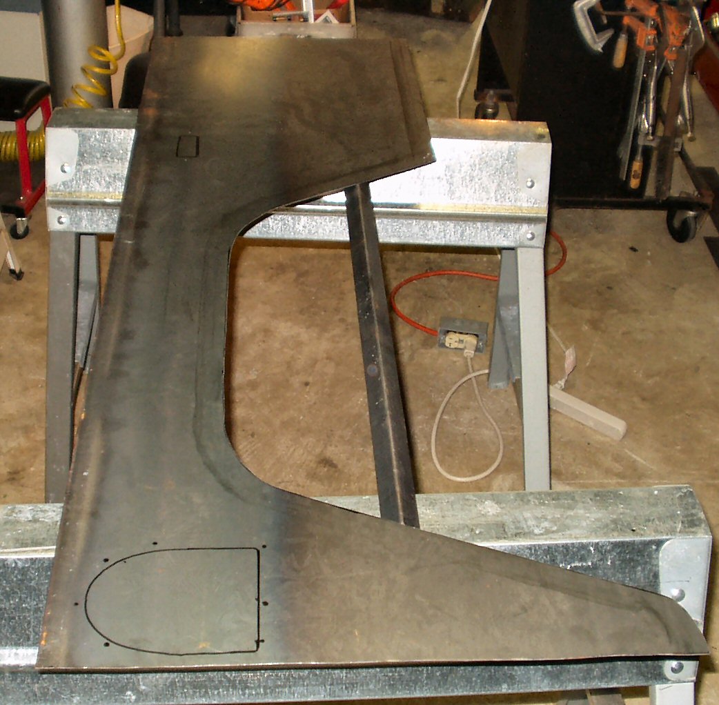
Ok remove the old panel and set the new panel up on a flat
surface where you can work on it. (Saw horses and a piece of thick plywood
work great.) Use a straight edge to connect all the lines so you have a continuous
guide line to follow while cutting. On the rear section where it curves you
want to extend the line all the way to the edge. We will cut out the area
for the bumper by hand after getting in tacked in place.
Use whatever method you prefer to cut out the new panel.
I recently bought a new jig saw from Northern Tools with the orbital function.
It is a great improvement over my old one for cutting metal! If you use this
method use a bi-metal blade at 24 TPI. Wear earplugs!
Fig. 18 shows the panel
after cutting it out. I then drilled some 5/16" pilot holes and cut out
the fuel filler hole ( See Fig. 19) and the marker
light hole.
Fig. 20
Tacking on Stiffening Edge
Fig. 21
Primed Tub Rail
Fig. 22
Test Fitting
Fig. 23
Fixing the Edge
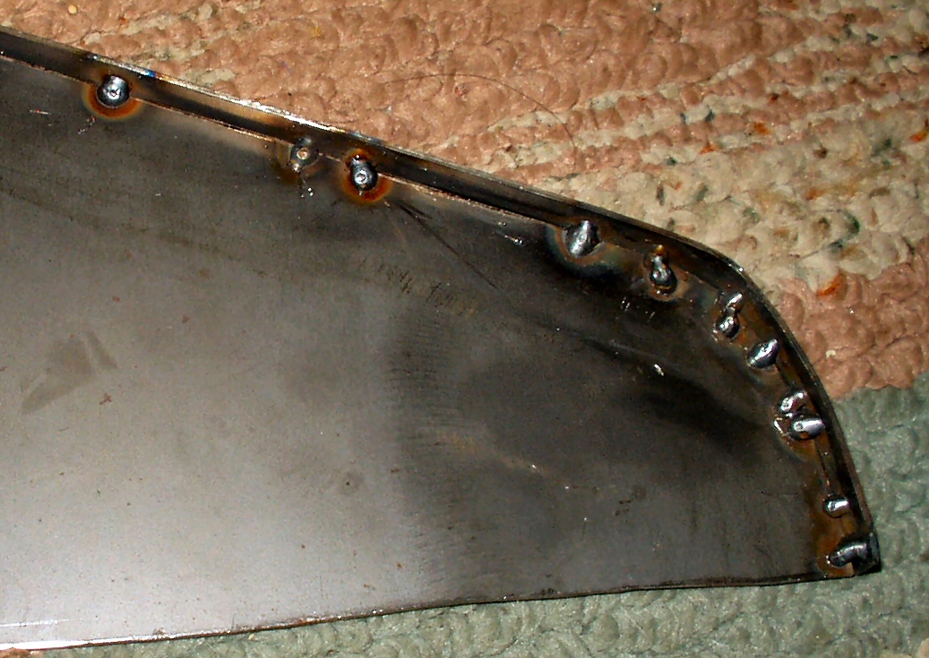
Next I used the jig saw and cut out a 1/2"
wide x 52" long 16ga strip from the scrap material.
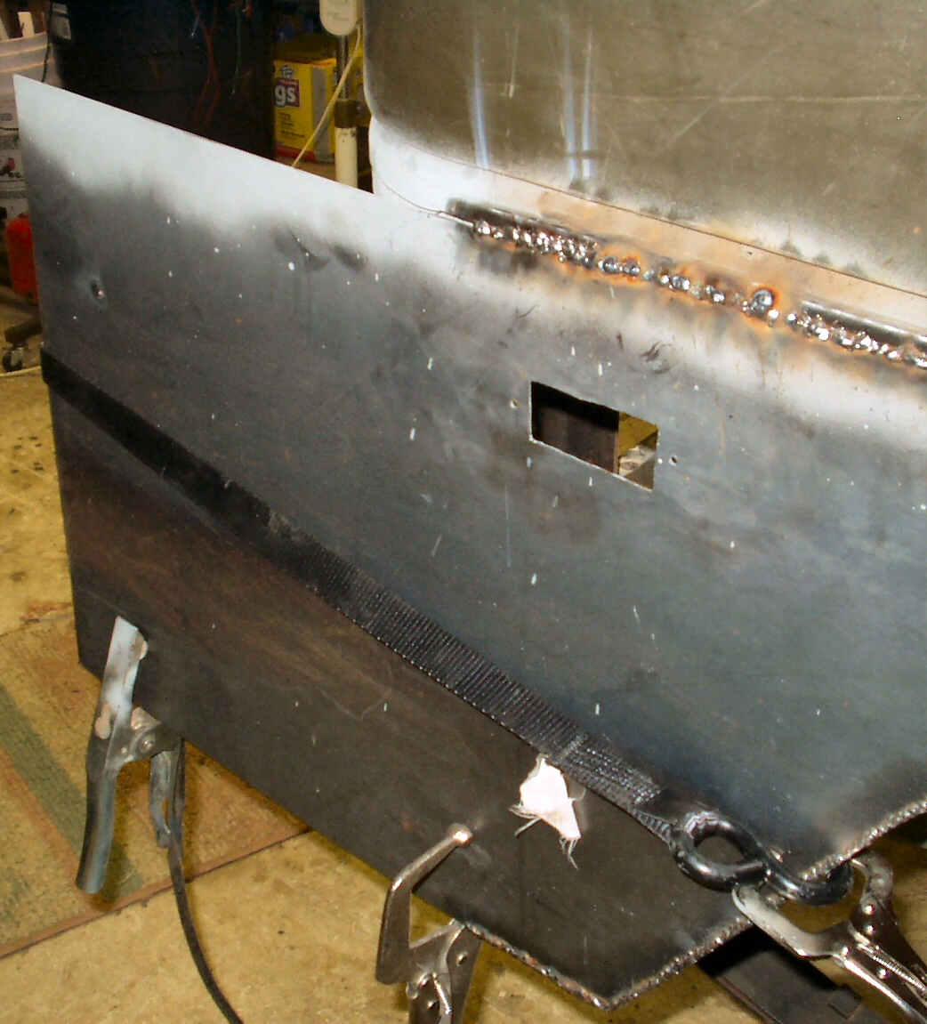
Make sure the new panel is perfectly flat (I laid mine back
on the floor) and start tack welding this strip to the BACK edge of the panel.
Make sure you have the strip placed so that when mounted on the truck the
strip is INSIDE the wheel well not outside! The strip is very flexible enabling
you to conform it to the curves of the panel easily. Make a tack weld, bend
the strip against the edge, make another tack weld. Keep doing this while
allowing the panel to cool completely after about 3 tacks. You WILL warp the
edge if you try to weld too many tacks at once! What this strip does is strengthen
the panel just like the OEM stamped panel. We will fill in the edge gap with
weld once the panel is mounted to the truck.
Now use a drill mounted wire brush and remove the rust from
the tub rail and prime it thoroughly with a weld thru primer. See Fig.
21.
Now with a helper clamp the new panel to the tub to see how
it all aligns up. I had a bit of work to do it this area! See Fig.
22.
Well it did not line up cleanly. At first I thought the tub
had settled. Remember I warned you to make sure you used a good factory cut
edge for the part of the panel that butts against the door post? Well I did
not and the edge was not square! Anyway Fig. 23
shows how much I had to trim off to make it square.
Fig. 24
Clamps
Fig. 25
Filling in the Welds
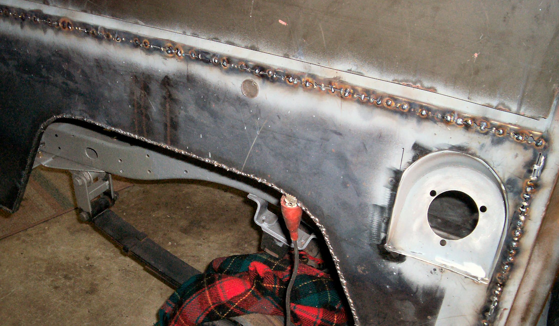
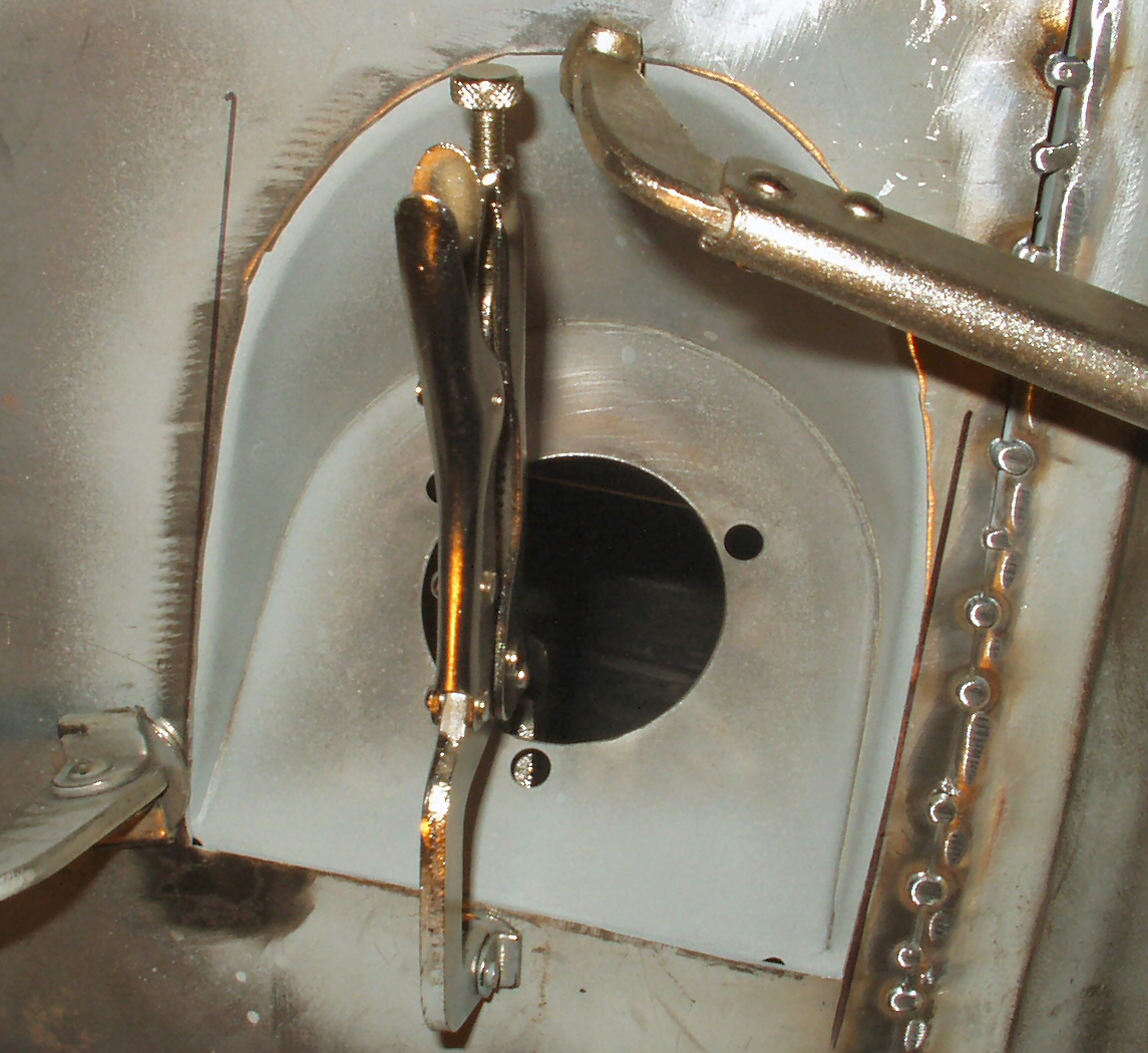
Make sure to prime all the metal that will be hidden when
you weld the panel in place. I primed about 2" down on the front and
back for good measure using a weld thru primer. I was able to clamp the panel
in place using welding clamps placed through the gas filler hole and side
marker hole. See Fig. 24.
Start tack welding the panel in place. Use smaller wire (.021
- .024) and turn your heat down so the edges of the panels don't erode away.
Check the panel EVERY WHERE for proper fit before you get too far with the
welding. Once you are happy with the fit then start tacking for real. Using
the holes drilled in the top rail lip, plug weld the panel to the rail. Do
one, then move to the other end and do another. Stop for now, you need just
enough to hold it. Now starting with the panel to door post place 3 tacks
about 1" apart. Move to the other end just before where the tub rail
starts to curve and make three tacks also 1 " apart then go to the middle
and make three tacks. This keeps anyone section of the panel from getting
too hot. Continue tacking in the panel until you have the gap completely filled.
It will take forever but be patient, you don't want it to warp! See Fig.
25.
Once you have the panel tacked in place we can start the
bending process. First make sure to tack the top edge all the way to where
the tub starts to curve. Also make sure to clamp the bottom of the panel to
the rear sill curved 'horn'.
Attach a ratchet strap to the curved area of the panel as
shown in Fig. 26 and 27 and attach
the other end to something solid that is behind the panel. See
Fig. 27. I used the drivers side seat belt anchor.
Fig. 26
Attaching Strap
Fig. 27
Another View
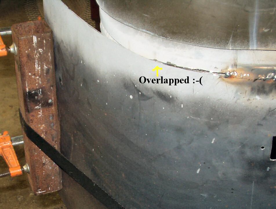
Fig. 28
Overlap problem
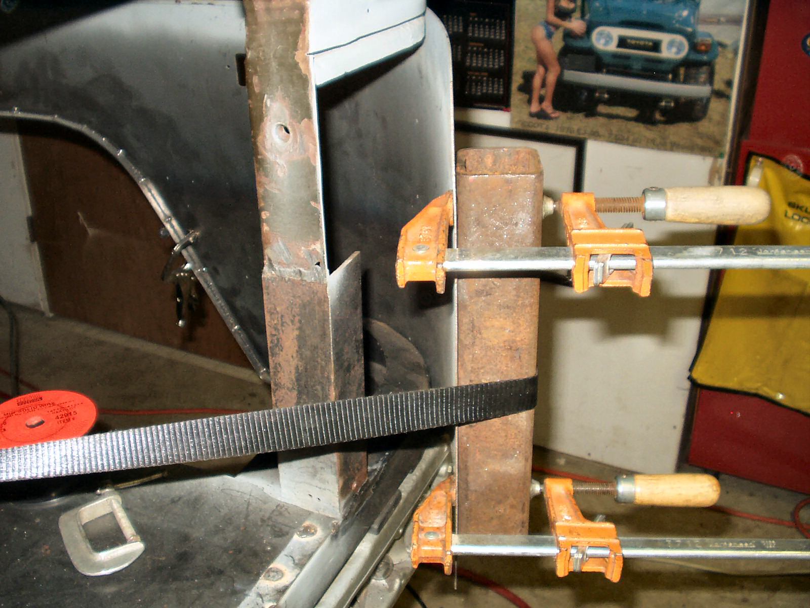
Fig. 29
Getting there!
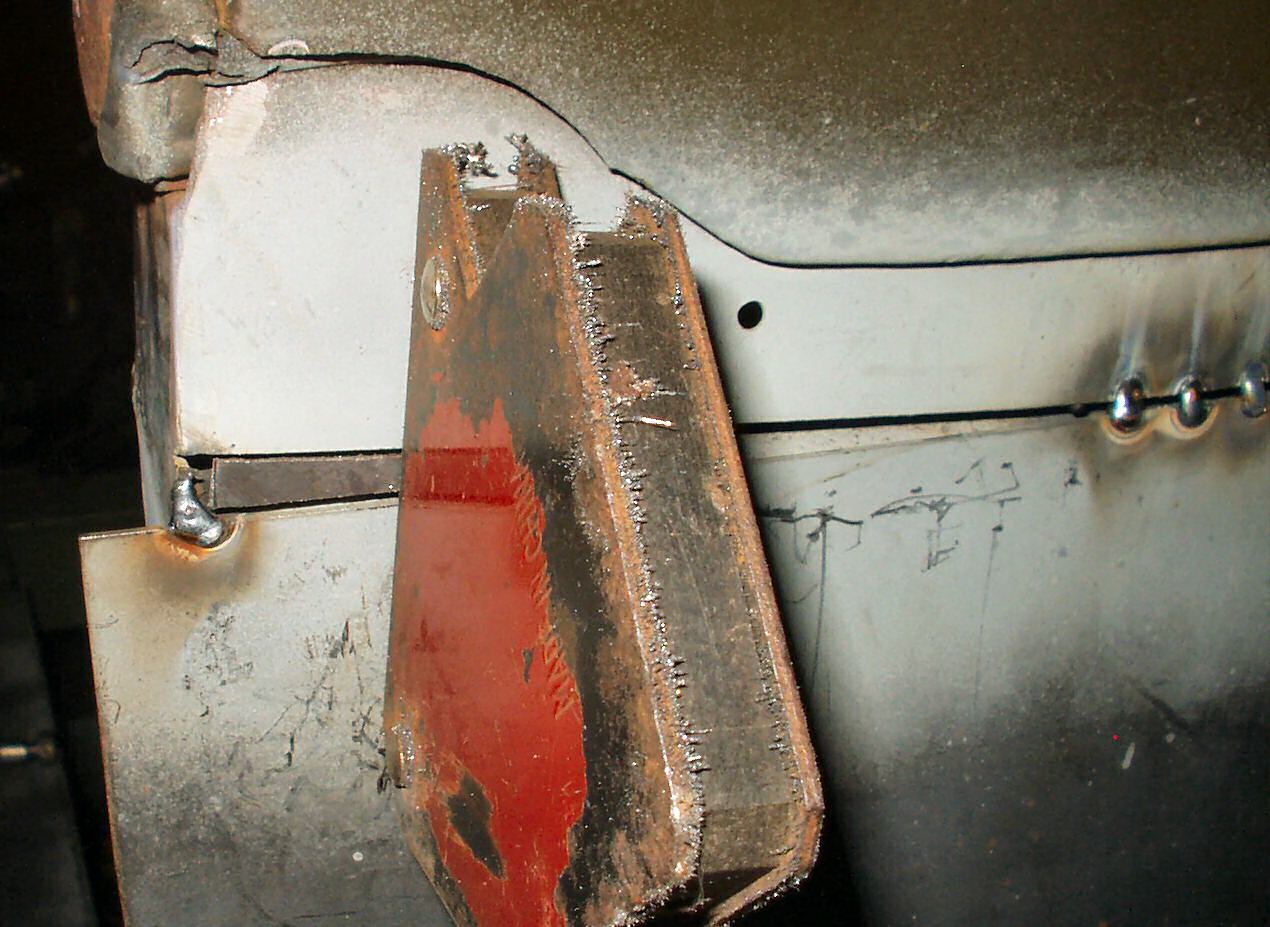
Fig. 30
Alignment Issue
Slowly start tightening up the strap. As the panel starts
bending check the alignment with the tub edge. I had a problem here. Something
was not lined up correctly and the panel was overlapping the edge. Since I
could not move the panel or the tub I had to use a cutoff wheel a couple of
times to make them even. See Fig 28.
As the panel gets around the cuve and more tension is required
to move it the panel edge will have a tendency to warp where the strap goes
over the edge. Clamp a stiff piece
of metal to the edge of the panel. This helps keep the edge from bowing when
the strap is tightned. See Fig 29. If your piece
is long enough for the clamps to clear you can continue to ratchet until the
edge is close then use additional clamps to clamp it to the vertical support.
Mine was not and I had to take the clamps off to finish.
Fig. 30 shows the other
issue I had. When I made my sill I must have made the horn stick out just
a tad too far on the passenger side. This caused the panel to be tipped down
about 1/8" at the edge. I had to use some very small filler pieces to
fill this in. I turned the voltage way down and carefully filled in the large
gap. It will add a few more minutes with the grinder :-(.
Next I used a jig saw with a good bi-metal blade and trimmed
off the excess panel as close to the vertical support as possble. Then a grinder
with a 24 grit flap wheel to make the panel even with the support. Then fully
welded the panel to the support.
Now put on your ear plugs, and face shield, start your fan
blowing to blow all the dust out of the garage and spend the next two hours
grinding down all your welds! See Fig. 31 and 32.
I'll have a few pin holes to weld up then the final grinding with a 120 grit
flap wheel.
Fig. 31
Welds Ground Down
Fig. 32
Back View
Mounting all the other stuff to the Panel
Now that the panel is welded in you can replace the gas tank
filler panel. Clean it up and give the edges a good coat of weld through primer
like in Fig. 33.
Gas Filler Support
Fig. 33
Gas Filler Primed
Fig. 34
Clamped in place to weld
Fig. 35
Welded in ready to grind down
Fig. 36
Just Needs Paint!
If you have a few rough edges from cutting out your gas filler
hole then now is the time to clean it up. Mine were a bit rough so I used
a file to smooth it out a bit. Don't spend too much time trying to get it
perfect. You will be running a bead of sealant around the gap between the
gas filler and the quarter panel. That will hide any minor imperfections.
Line the panel up until all the edges look correct then clamp
it in place.See Fig. 34.
Using the holes you drilled to remove it, plug weld it in
place from the back. See Fig. 35.
Tail Gate Hook Support
I removed the old tail gate hook backing
plate from the old quarter, de-rusted it then primed it with the weld through
primer and set it aside to dry.
I got my sorry excuse for a tail gate and
attached the drivers side latch then held it in place to see how everything
was lining up. It looked pretty good so I clamped the tailgate into position,
placed the hook into the latch, (See Fig. 37)
centered the latch, then used a transfer punch to mark the holes. I drilled
these out and bolted the hook to the backing plate and tack welded it in place
with a couple of tack welds. Now my tail gate will hang!
Fig. 37
Mounting Tail Gate Hook
Fig. 38
Mounted
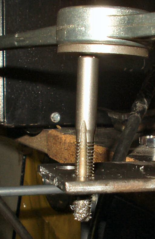
Side Marker Light Screw Support
Now we can add the side marker light supports. I used the
ones I removed from the old panel. After I de-rusted them and re-tapped the
thread I welded on a 6mm x 1.0 stud to use for a ground. This way when I Duraback
the tub I won't have to scrape it off to find a ground.
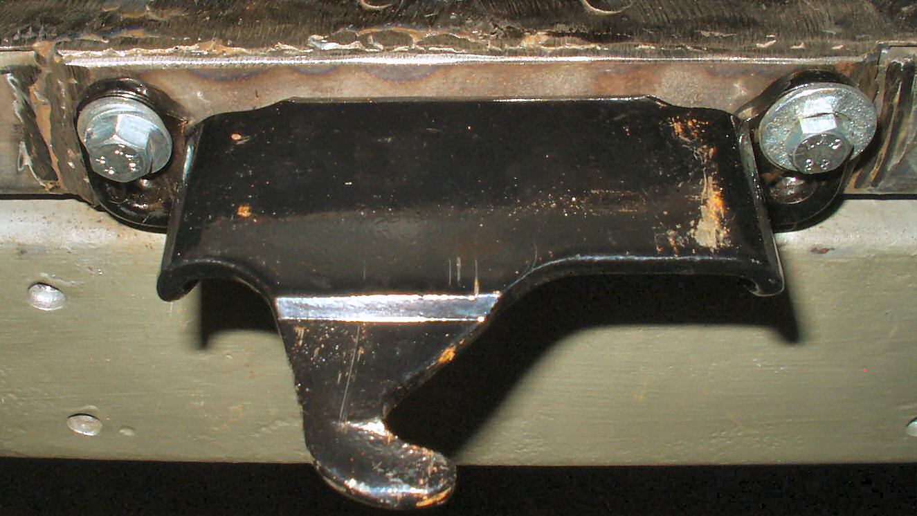
Tire Carrier Supports
The tire carrier presents some special challanges. It is attached
to the body with 8 bolts. Four of them go through the rear sill horn and four
go through a backing plate on the inside. A long time ago, when I did the sill,
I had drilled the holes in the horn while the tire carrier was still attached
so I would not have to spend a lot of time measuring. So the next step
was to get the top holes drilled. The top backing plate was marked before removing
it so I could put it back exactly where is was (See Fig.
14) I clamped it into position using a large
welding clamp then used a transfer punch to mark the holes on the inside of
the quarter. I drilled them out using a 19/32 drill bit then lifted the carrier
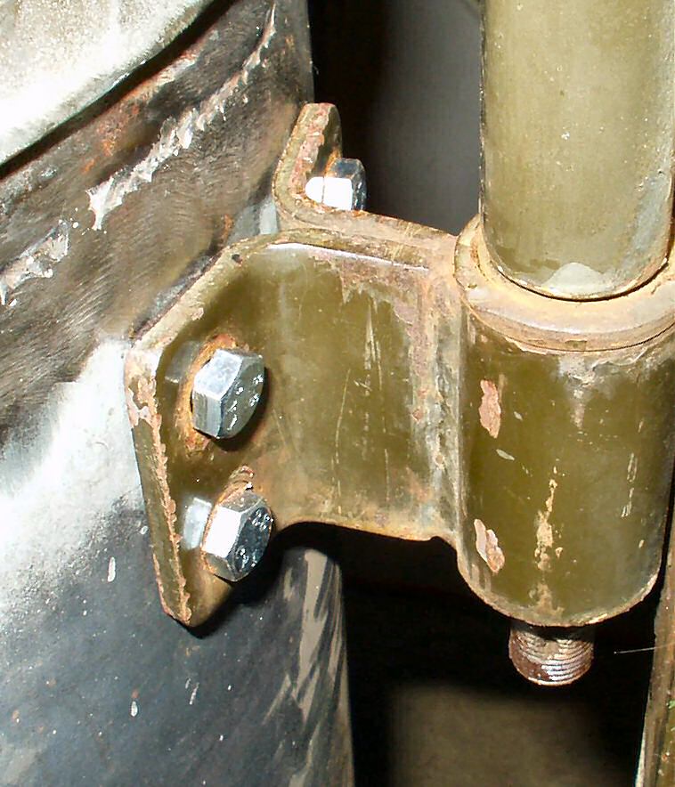
in place and bolted it loosely. See Fig. 41. Next
I used the transfer punch to mark the bottom holes and drilled them out. Now
comes the moment when you see if all the cutting, bending, and welding has distorted
the body to the point that nothing lines up correctly...
Fig. 41
Top Mount
Fig. 42
Aligning Carrier
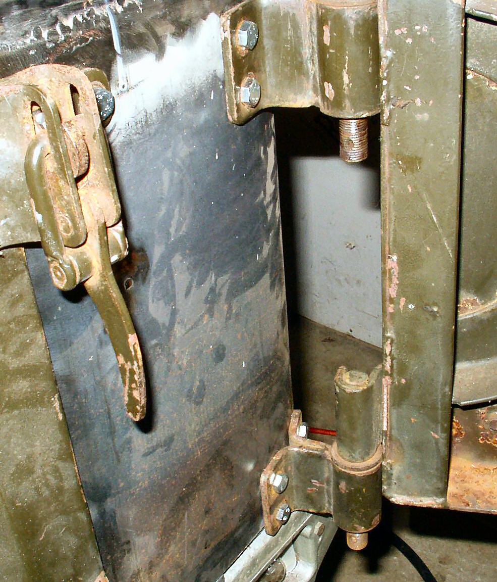
Fig 43
Mounted
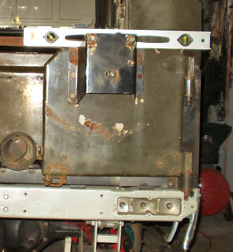
Close! After putting a level on the top of the carrier I determined
I would have to raise it about 3/8" to be level. See Fig.
42. This was easily acomplished by moving the bottom hinge left and the
top hinge right. I tightened down the bolts top and bottom then checked the
swing of the gate. Besides groaning from lack of lube it swung pretty good!
Next I welded the nuts for the bottom hinge to the sill horn so that I can remove
the carrier with only one wrench.
Fig. 44
Latch Mounting
Fig. 45
Tapping Holes
Fig. 46
Clamped ready to weld
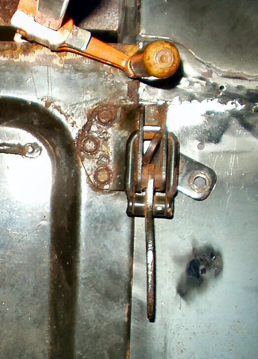
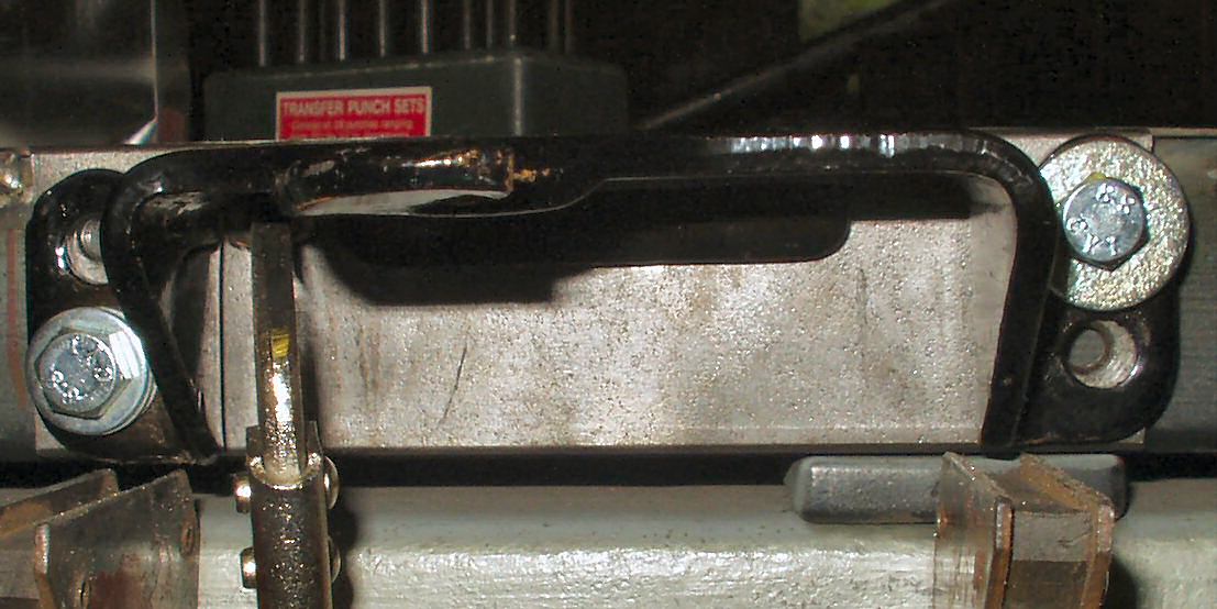
Ok, I had it mounted, level and swinging. Now to get it latching!
I got the stock latch and held it in position on the rear sill with a couple
of welding magnets. See Fig. 44. When I closed
the carrier it became apparent that something was not quite right. The
latch was about 1/4" back too far and would not engage. After thinking
about this I came to the conclusion that several things conspired to make this
off. First was the sill was not exactly flush with the rear bumper and second
the quarter panel was not an exact replacement of the stock one so that was
throwing it off. Anyway I needed a 1/4" spacer for the latch. I cut one
from some 1/4 x 2" strap I had, used the transfer punch to transfer the
holes, drilled them out then tapped them to 8mm x 1.25. See Fig.
45.
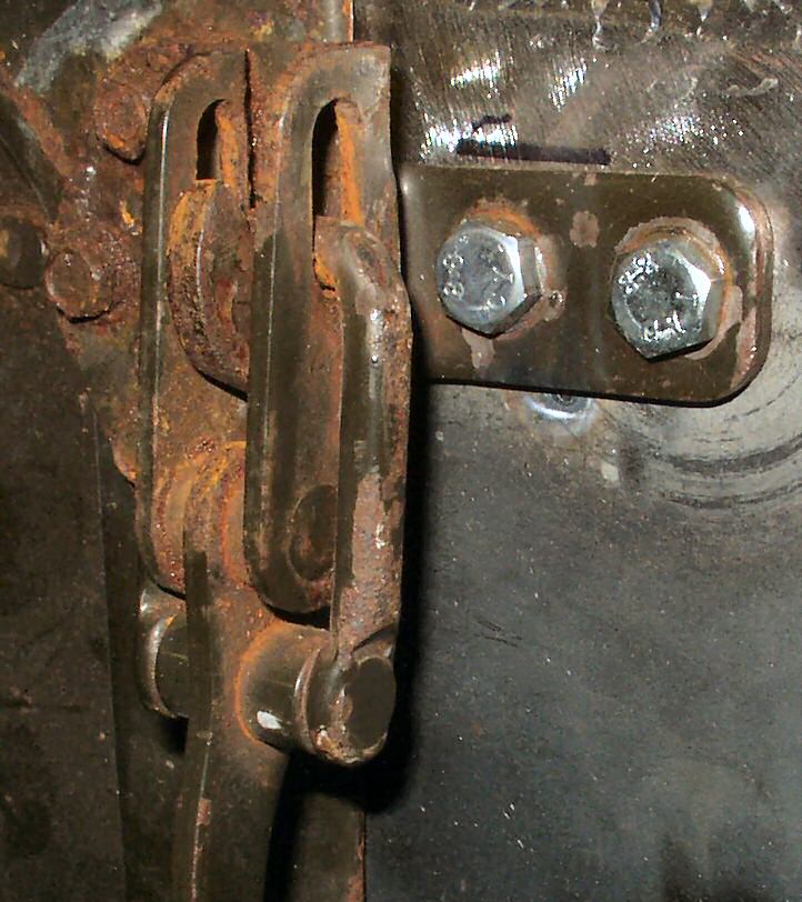
I used some bolts spaced out with washers and bolted the latch
to my spacer then clamped it to the sill to determine where it was to be welded.
See Fig. 46. I will have to get some short bolts
or grind down some to make it fit. I did not want to drill into the sill as
I have it water tight currently and don't want a water trap!
Fig. 47
Looking Good!
After quite a bit of cyphering out where the latch needed to
be I finally tacked it into place, tested that it closed firmly against the
tail gate (make sure the rubber bumpers are in place), then burned it in. After
I ground down my welds it looked pretty good! See Fig.
47.
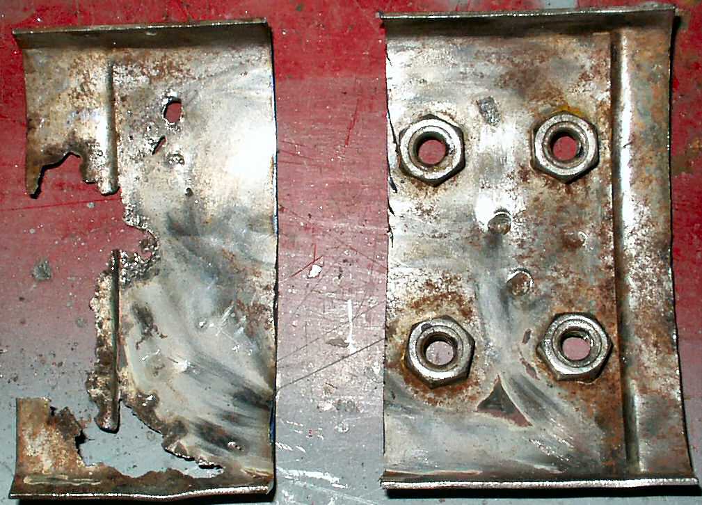
Before I could repair the top spare tire carrier backing support
I had to actually finish the wheel wells so this is a bit out of sequence!
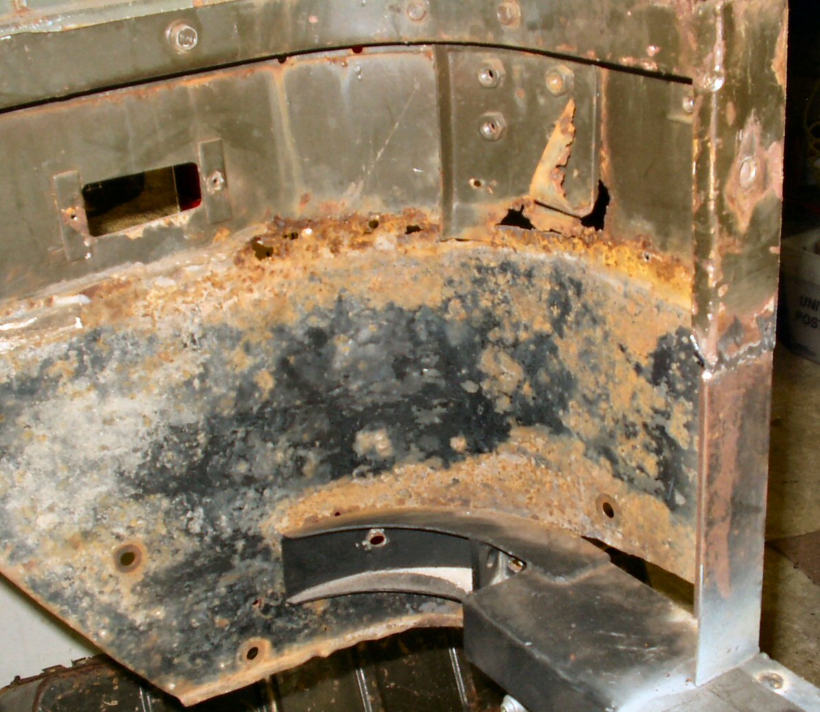
Fig. 48
Cutting out Rust
Fig. 49
Making Patch Panel
Fig. 50
Bending Curve
Fig. 51
Front Welded
Fig. 52
Welded Back
I started by cutting the bad part off. See Fig.
48. I then placed the bad piece between two blocks of steel and used
my hydraulic press to flatten the piece completely. This was used as a template.
I laid it on a piece of good 16ga and traced around it. After cutting it out
I used the press to make the slight offset on the bottom. See Fig.
49. I used the outside of the quarter panel to hand bend the piece to
the proper curve. See Fig. 50. Then clamped it
in a vice and bent the edges to match the top piece. Next I tack welded the
pieces together and ground down the welds as best I could. See Fig.
51-52. This piece will be installed when I do the wheel wells.
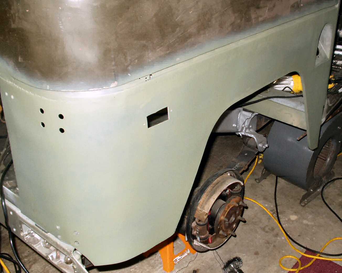
Fig. 53
Primed Quarter
Finally I stripped everything off, used a 3M pad to smooth everything
down and rattle canned a self etching primer on it. This will hold it until
I top coat.