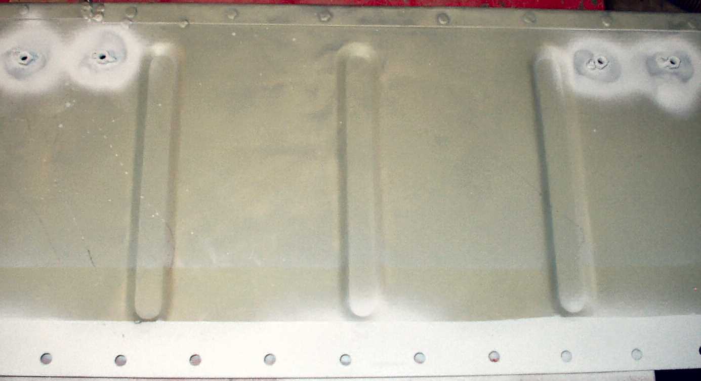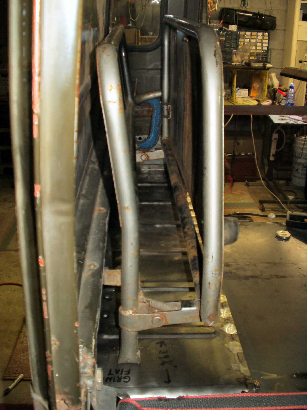
Fig. 1
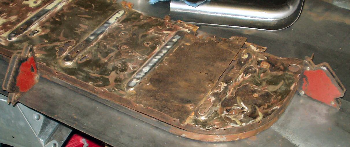
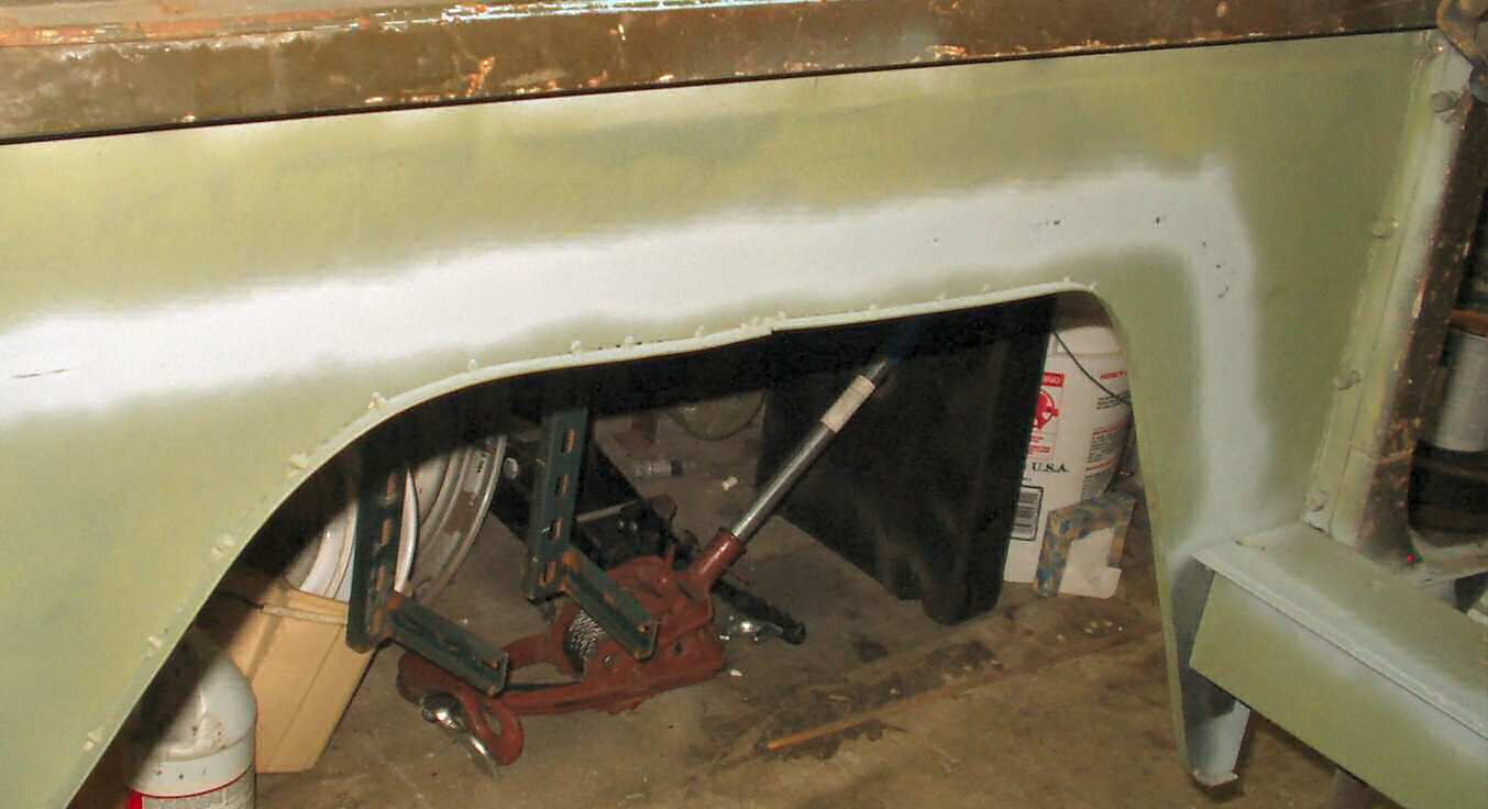
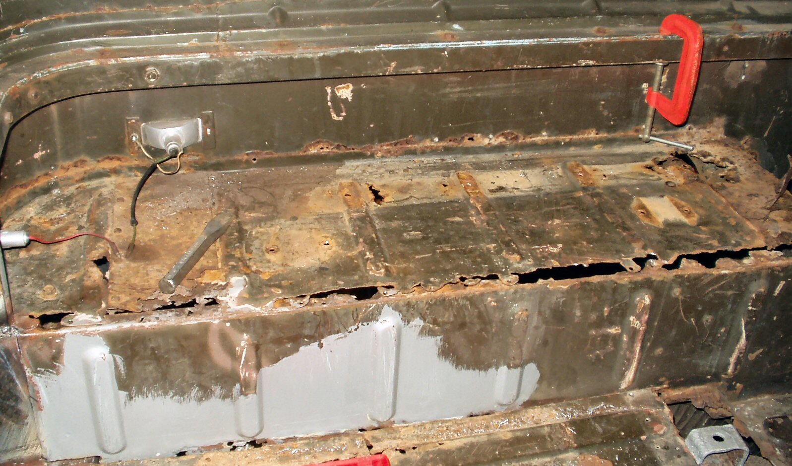
Drivers Wheel Well Before Removal
![]()
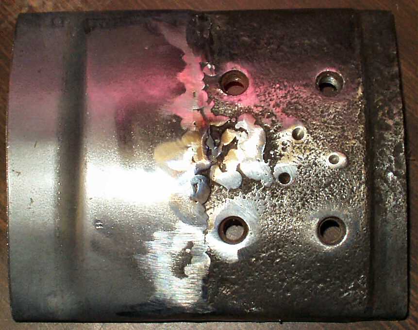
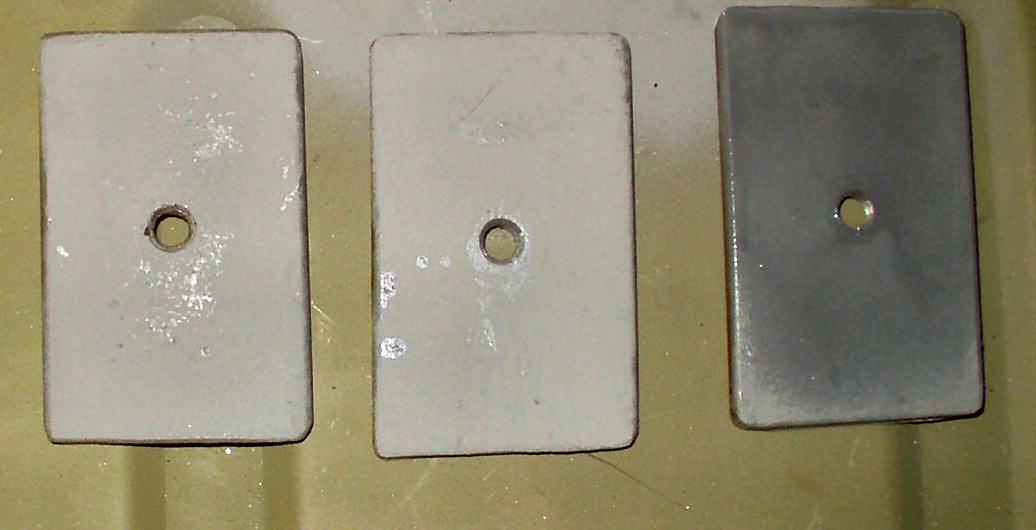
Fig. 2
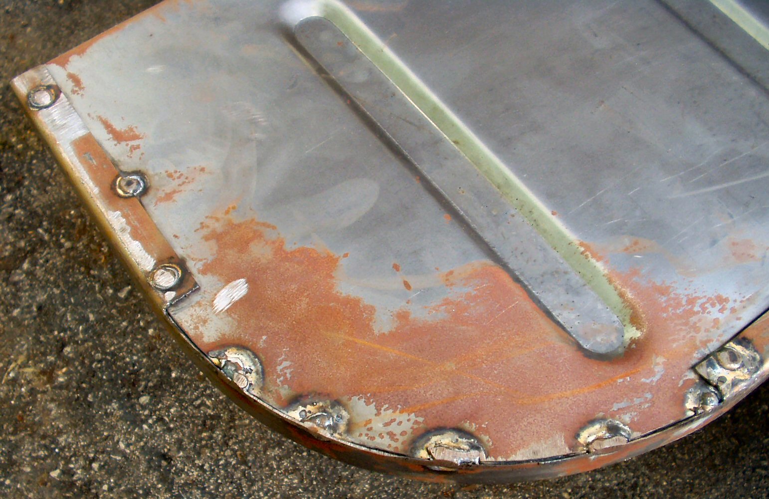
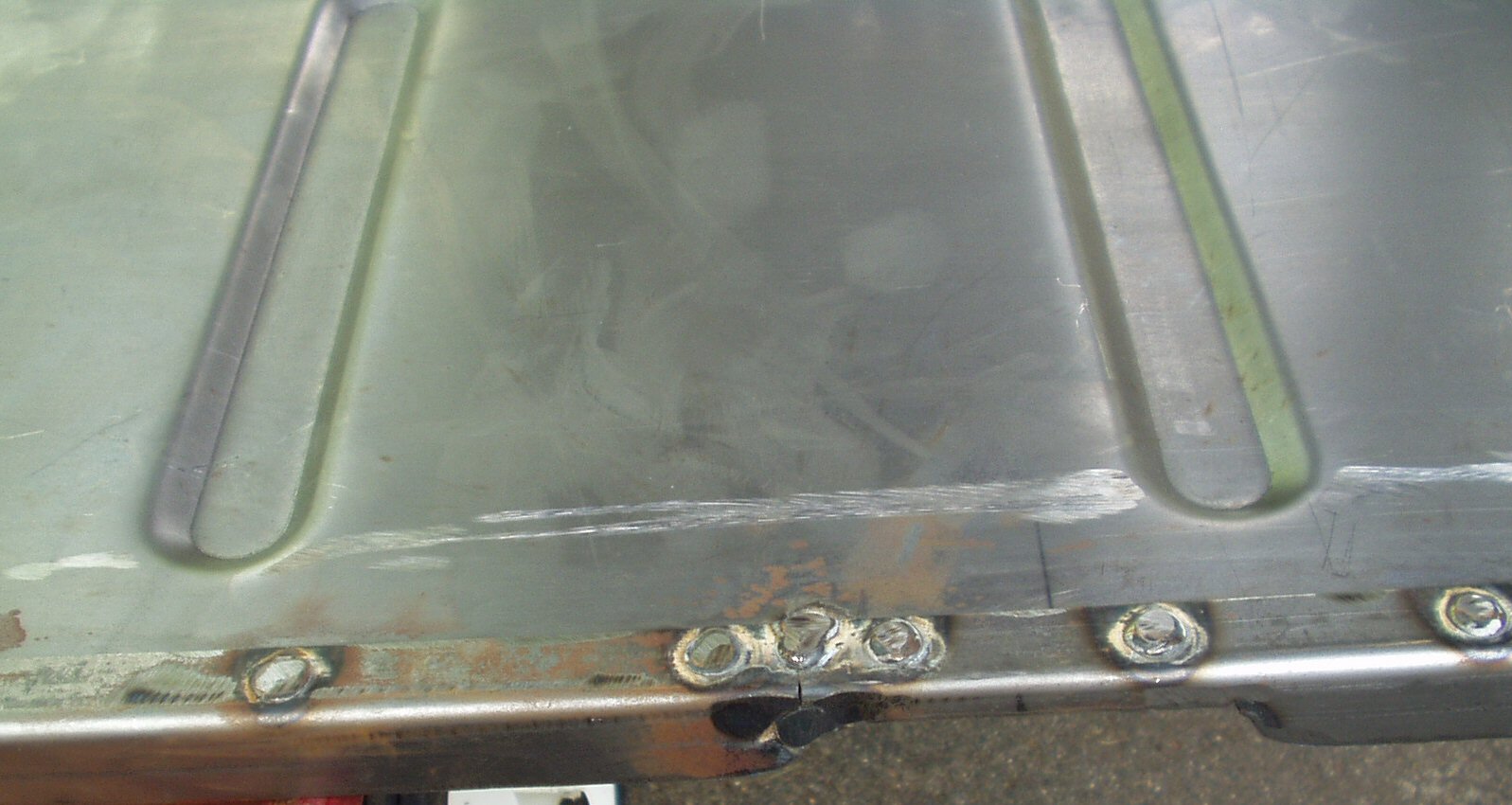
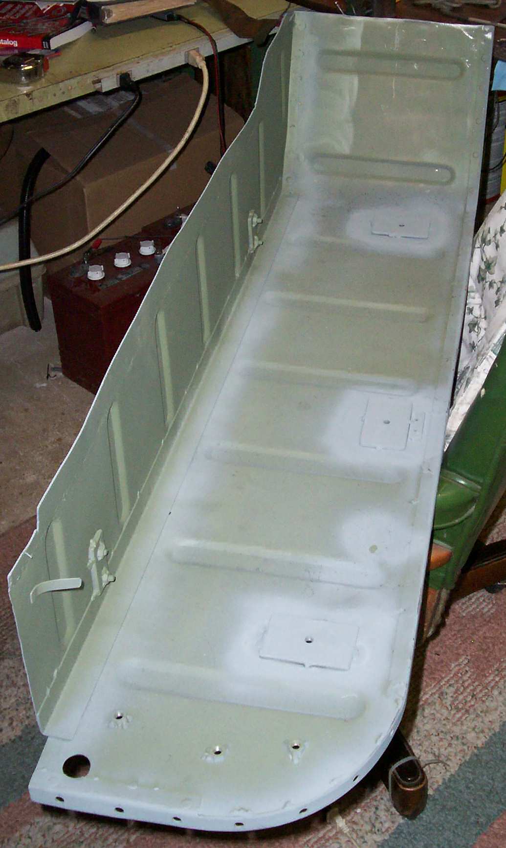
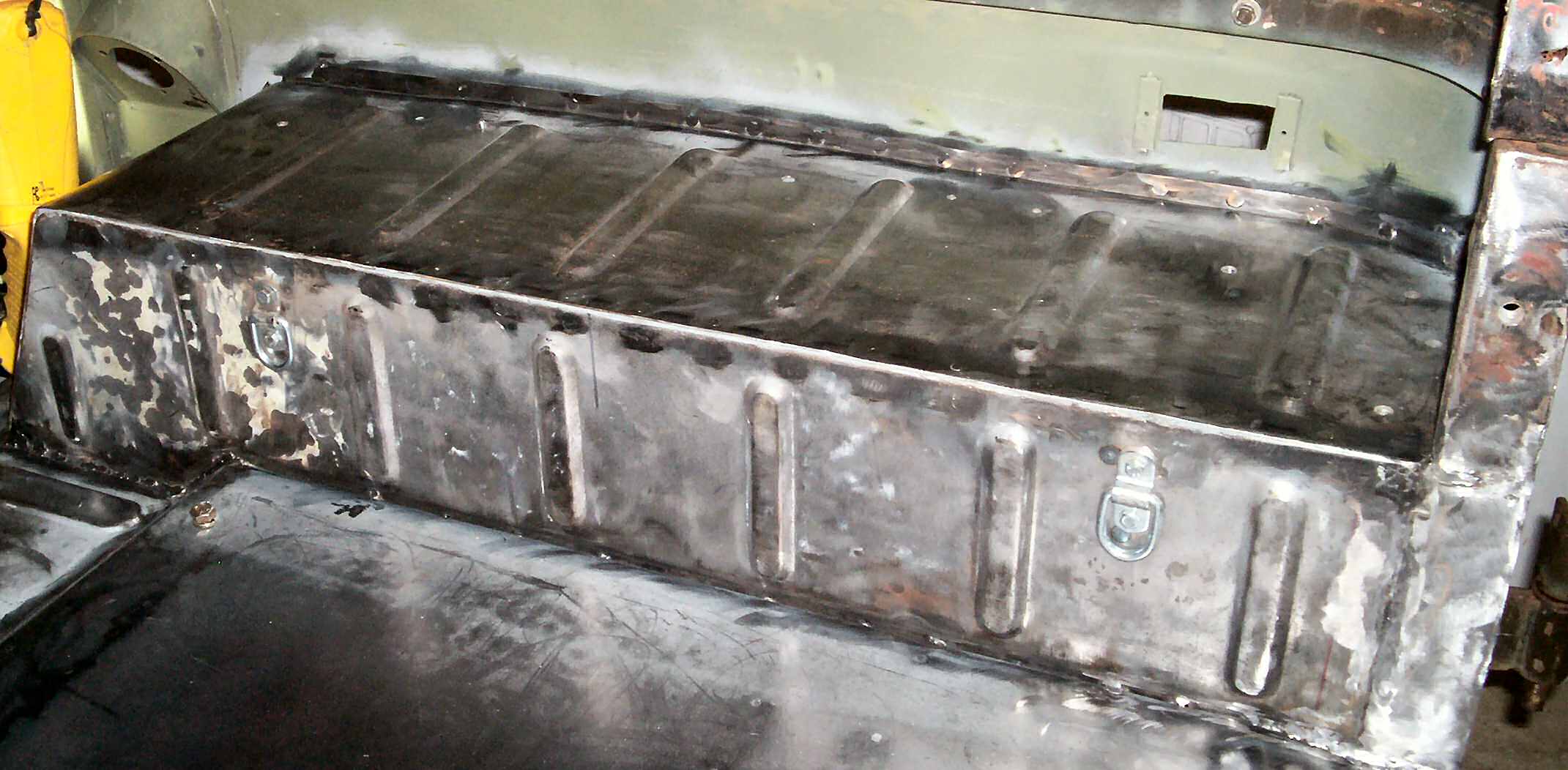
De-Rusted Top
![]()
Fig. 3
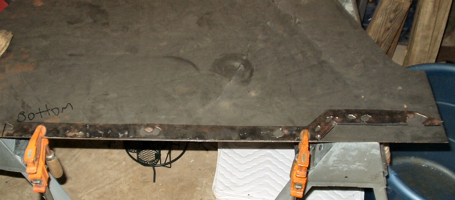
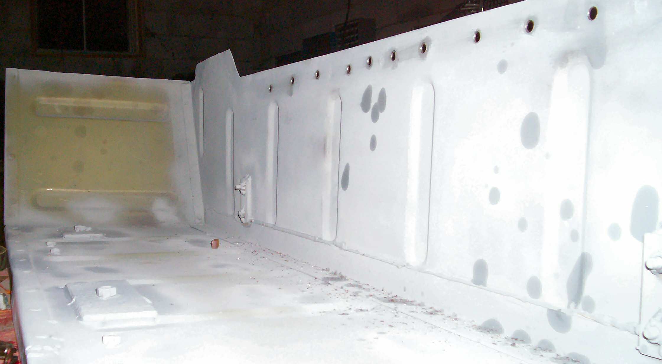
Bottom
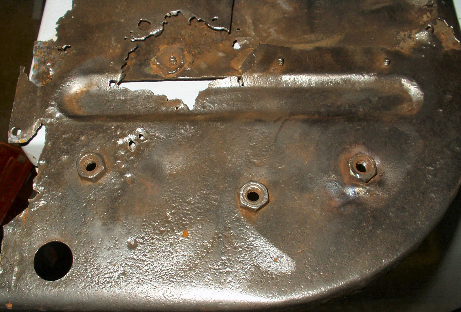
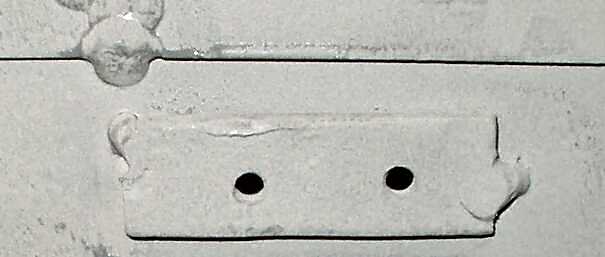
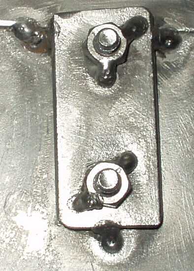
Fig. 4
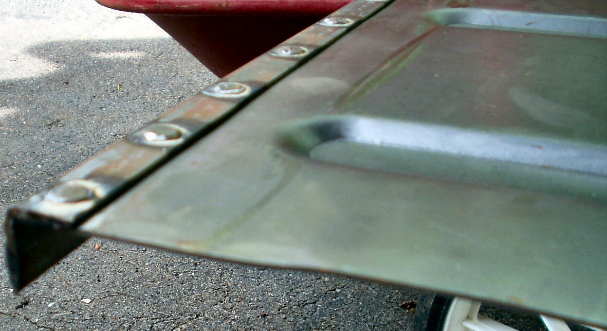
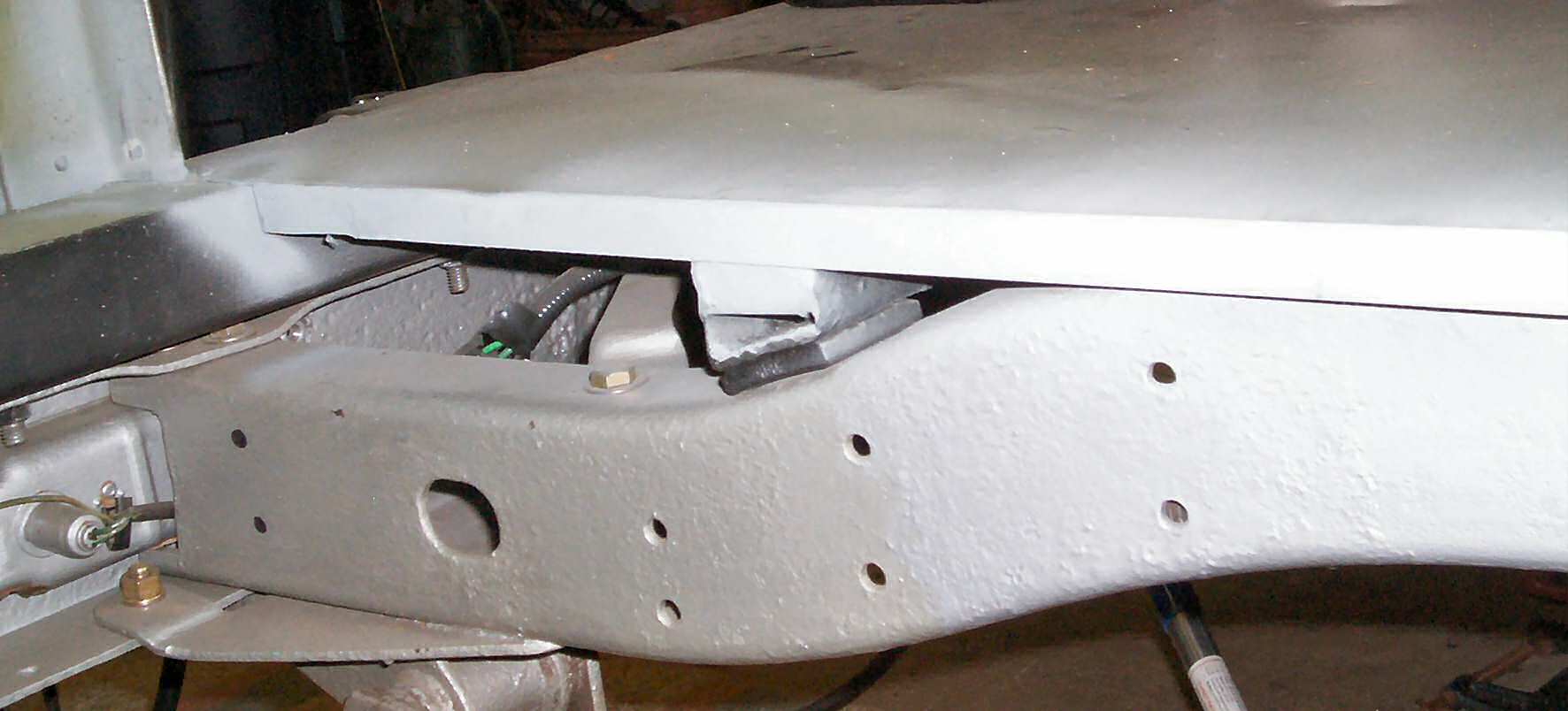
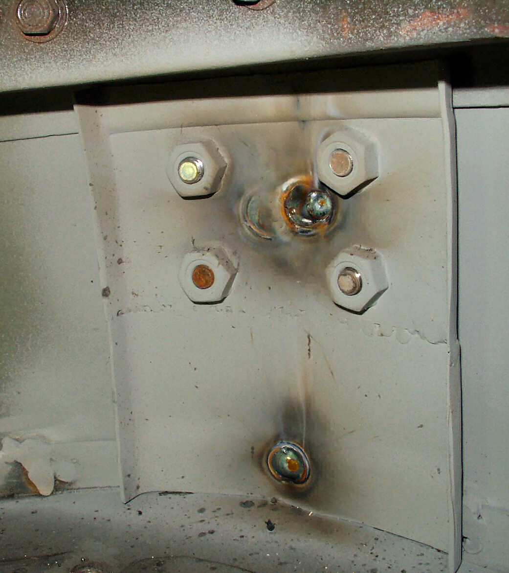
End Close up
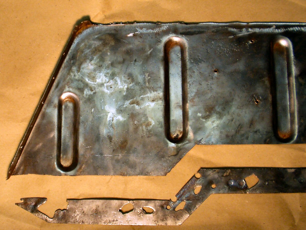
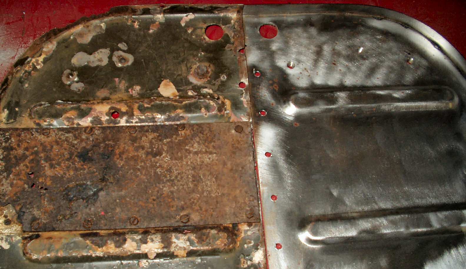
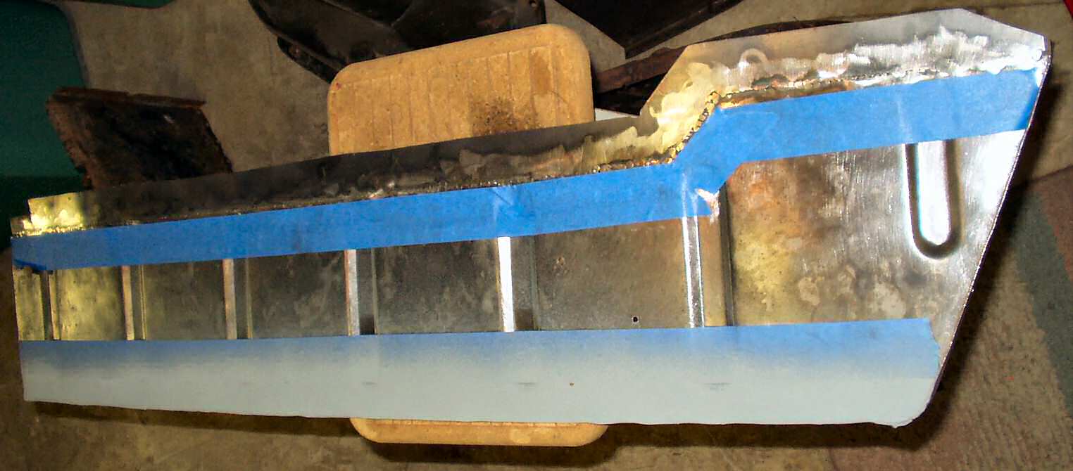
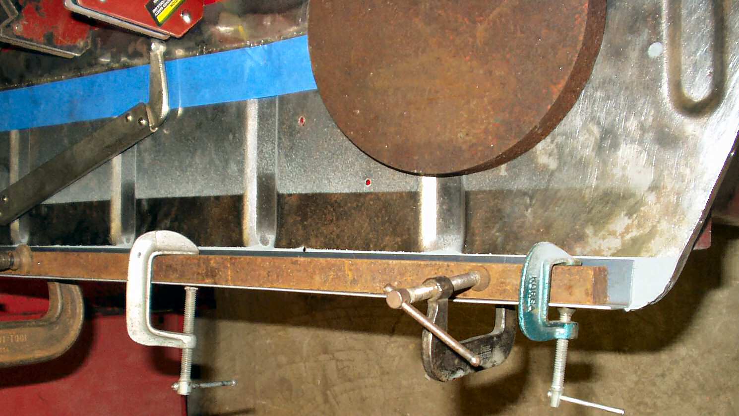
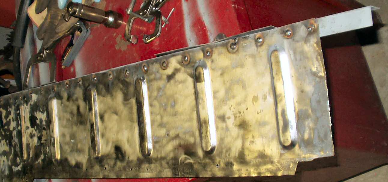
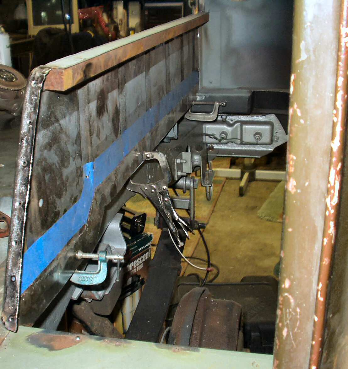
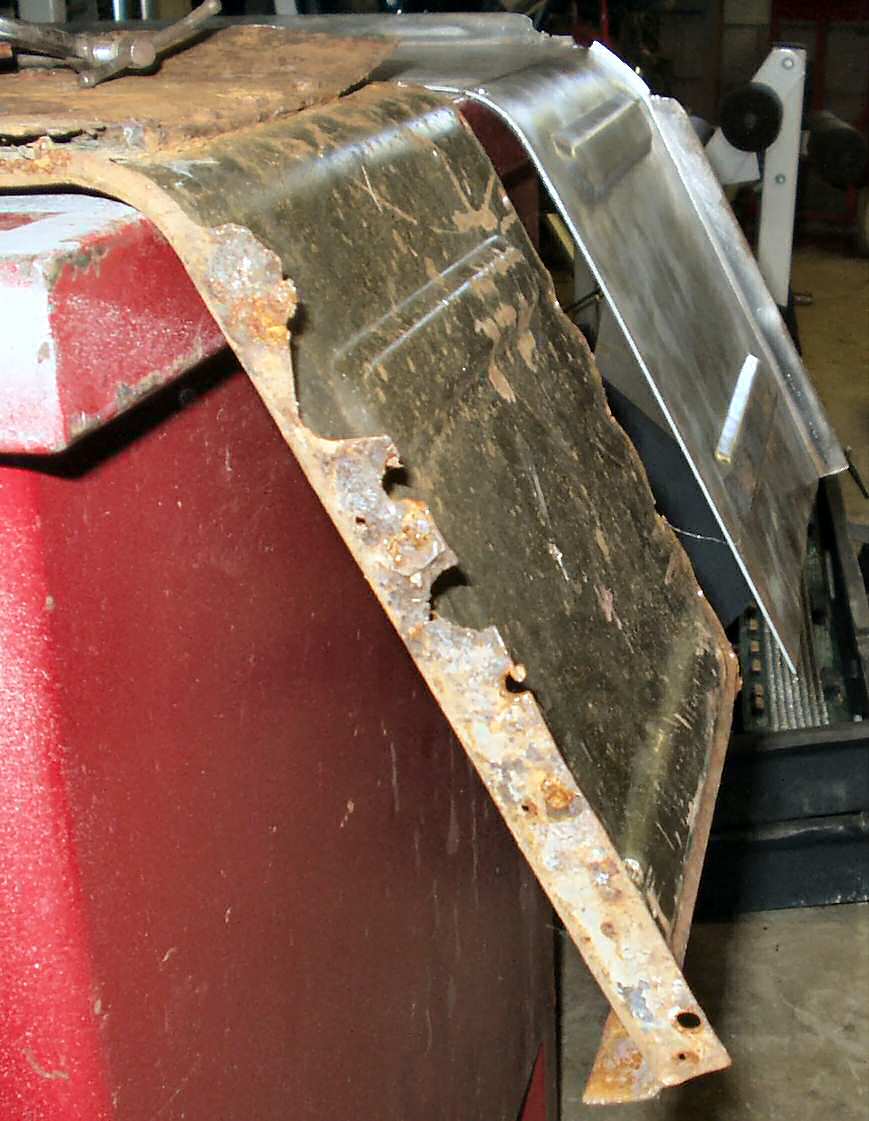
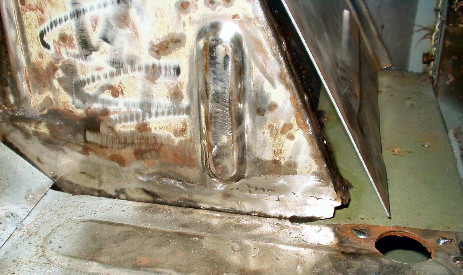
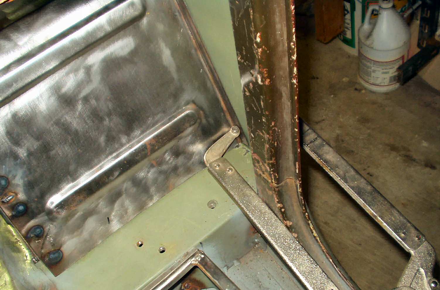
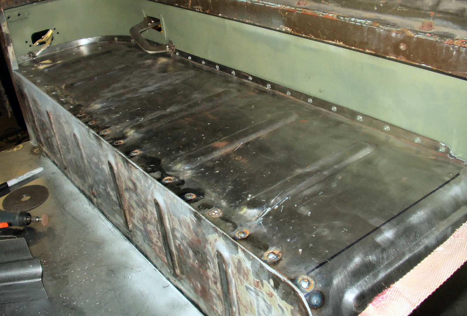
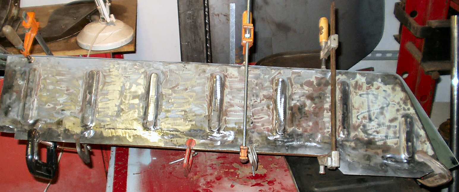
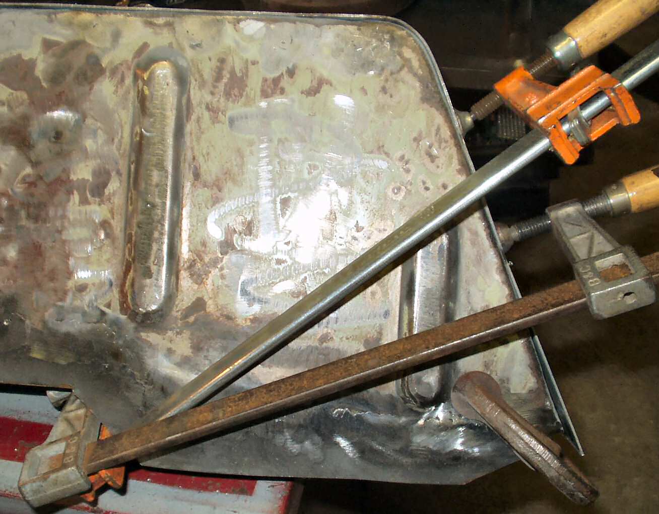
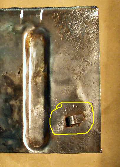
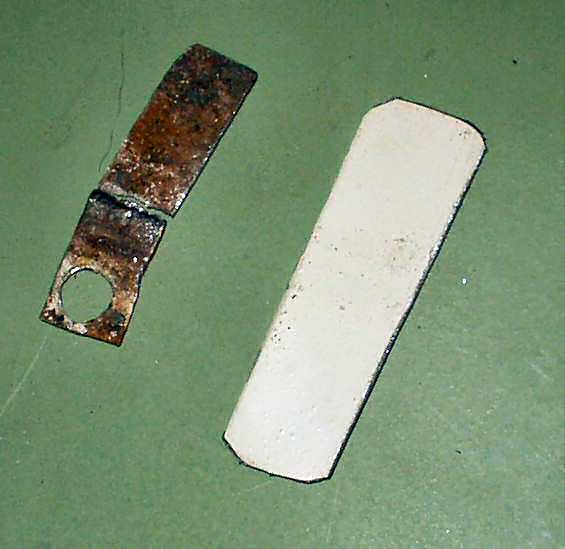
Though I am not restoring the truck I wanted to retain the stock look where ever possible. To do this I have been 'repairing' panels that any sane person would throw out in an instant. However the tops of the wheel wells were so rusted that there was simply no way they could be salvaged. I REALLY considered it. I even put the wheel well in the de-rust tank to prep it for welding. When all the rust was gone there was hardly anything left to weld to! See Fig. 1-4.
Fig. 1 Drivers Wheel Well Before Removal
|
Fig. 2 De-Rusted Top
|
Fig. 3 Bottom
|
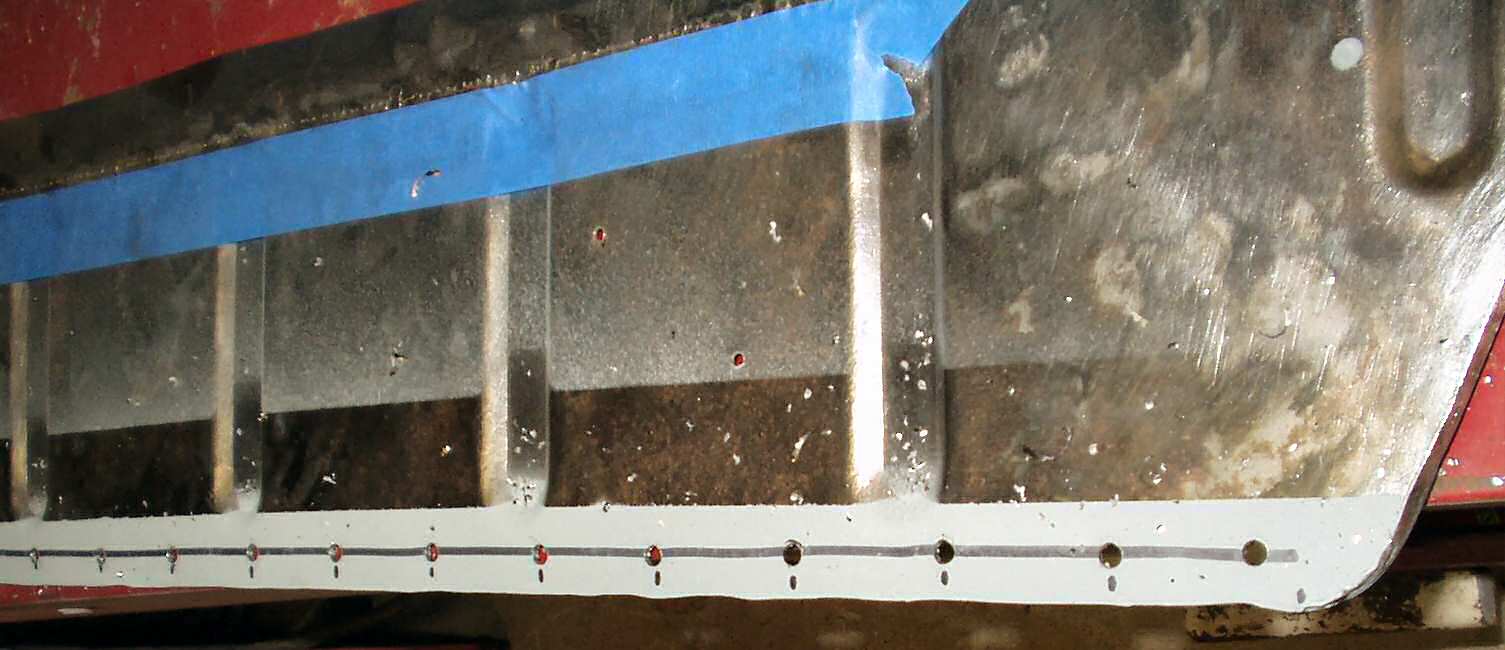
Fig. 4 End Close up
|
Note the following sections may contain pics of either the drivers side or passenger side as they are identical in all respects.
The wheel well side panels however could be salvaged so I separated the top from the side panel by drilling out the remaining spot welds. Next I used the grinder to remove what remained of the top flange running the length of the side panel leaving just a bit at the front that was in good shape. I will weld on a 3/4" x 3/4" x 38" replacement later to support the top. Finally using a jig saw with a bi-metal blade I cut out about 1.5" on the very bottom edge that was full of rust holes. See Fig. 5 . I used this piece as a template to make a new bottom edge from 16 ga sheet. See Fig. 6.
Fig. 5 Bad edge cut off |
Fig. 6 Marking the new lower edge |
Fig.7 Welding new edge back on |
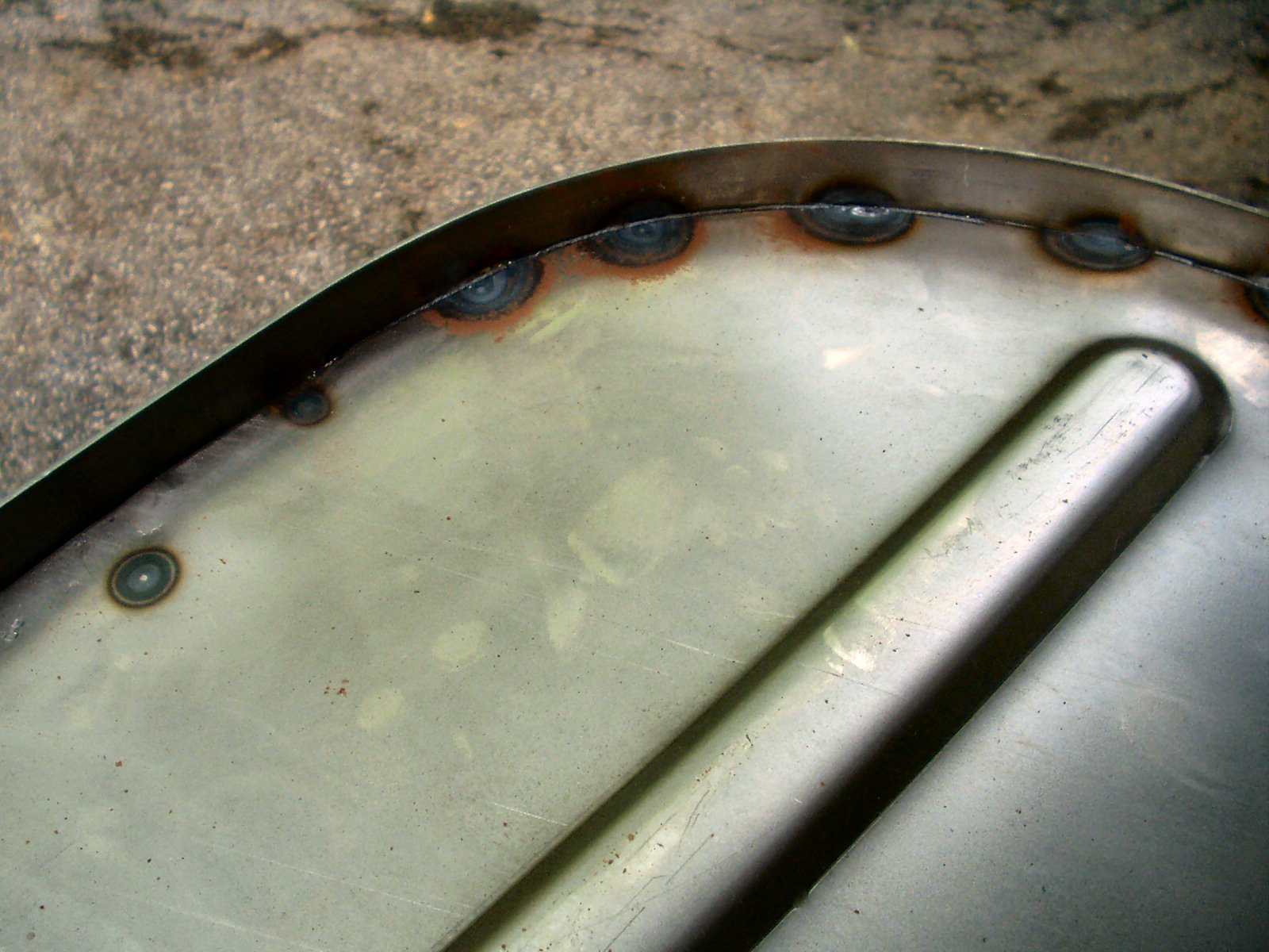
Fig. 8 Warped Edge |
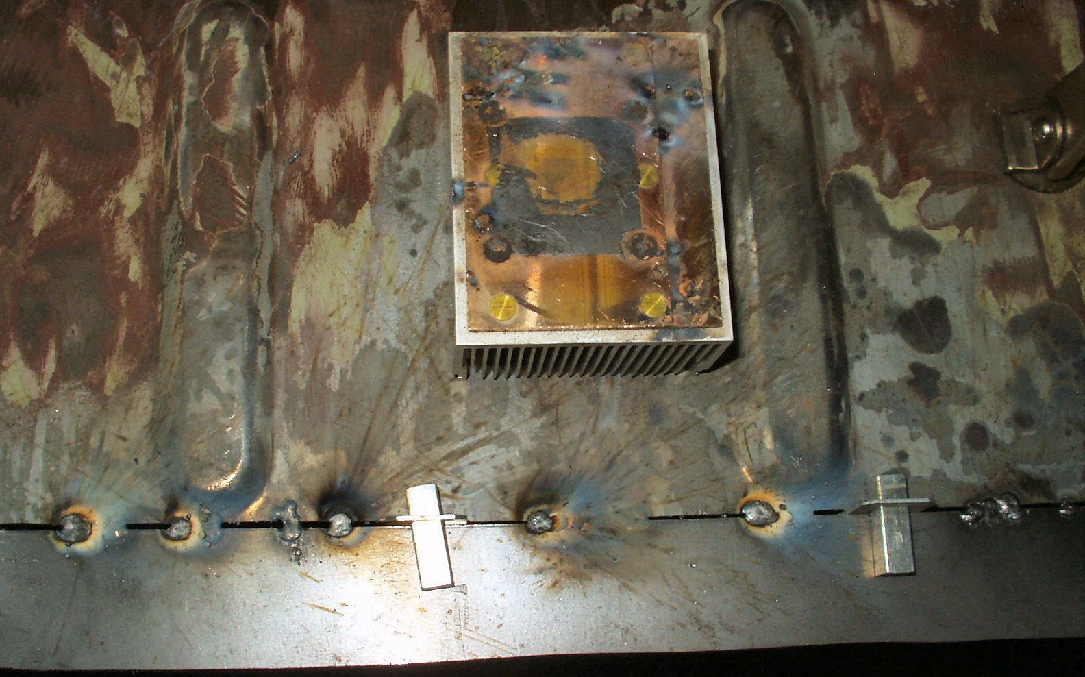
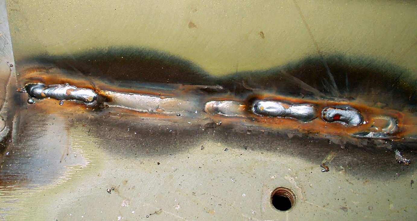
This was welded back onto the bottom of the panel. A lesson I learned about welding smaller thin sections to larger thin sections? The smaller piece will warp much quicker than the larger piece! I clamped a thick piece of angle iron to the large piece to help keep it straight as I welded. I used butt weld clamps gotten off E-Bay to hold the small piece to the large piece. You can see these in Fig. 7. Though I took great pains to not allow the metal to get too hot, the smaller edge piece warped anyway! I should have clamped a long straight edge on it too. You can see the warped edge in Fig. 8. Oh well, I'm learning as I go!
In Fig. 7 you may notice something else, a square block of aluminum with a copper top lying on the metal? I had always heard that weld would not stick to copper so I got a heat sink from an old computer microprocessor to try it. It works great! Not only does it support the weld it of course acts as a fantastic heat sink to draw the heat out of the weld area to help prevent warping. Even after repeated welds it was just warm to the touch.
So now I had to make a decision, make my own wheel well top or buy one. Believe it or not I decided to spend some, gasp! money! I looked at Canada Cruisers, CCOT and Real Steel Cruiser Parts (haneytools) on E-Bay
The Canada Cruiser parts are tough good looking parts. They are made from 14ga steel (original early FJ's are 16ga, later are thinner 18ga!) and have flanges for easy mounting BUT they don't carry anything for trucks older than 1973. :-( Good pricing but shipping would also be a factor.
CCOT parts are, of course, top of the line but they are VERY proud of them.
That left the 'new' guys. I had seen the Real Steel postings on E-Bay I had heard that the company is composed of some ex CCOT guys that went into business for themselves. The web site lists parts that even CCOT does not carry. (Tub rail replacement!!!) I poked around on the site for several weeks then decided I would make a best offer for two wheel well tops. I figured they would be rejected as being too low but got an email the next day saying they accepted my bid! I'd tell you what I bid but them I 'd have to kill ya... :-) Anyway they will be here soon.
Well they are here... I am sorry to report that I am NOT impressed with these :-( First it took over 6 weeks to get them. Next they are NOT a one piece stamping like OEM as the advertise on their web store on E-Bay. They are a stamped flat sheet with a 1/2" 16 ga angle strip spot welded around the edge. This edge will have to be sealed completely or they will rust quicker then the OEM panels. See Fig. 19 and 13.The welds are sloppy and a half assed attempt to grind them down was made. See Fig. 9and 10. The tops already had a very light rust starting on them when I got them due to no protective coating. The tops are also warped and wavy. See Fig. 13. Some instructions would have been nice though I don't require them.
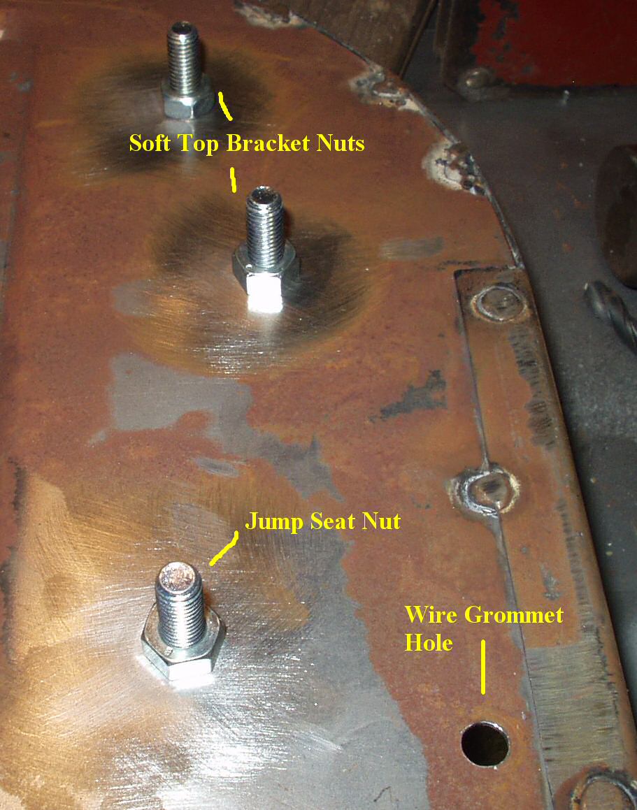
See anything missing? There are no holes drilled for anything that should mount on the panels. I will have to add the soft top bow mounts, jack handle mounts and wire grommet hole. Good thing I saved the old ones to use as a pattern!
Fig. 9 Rust Already? |
Fig. 10 Sloppy Welds/Rust |
Fig. 11 More Sloppy Welds |
Fig. 12 Edge Piece |
Fig. 13 Warped Panel |
Fig. 14 Overall View |
Now all of these defects except the warped panels I can take care of myself and I guess I should happy someone is making these at all but their quality control needs some serious work.
Fig. 15 Marking Holes |
Fig. 16 Ready to tack |
Fig. 17 1/2" Knock Out For Grommet
|
Fig. 18 Ready to De-rust |
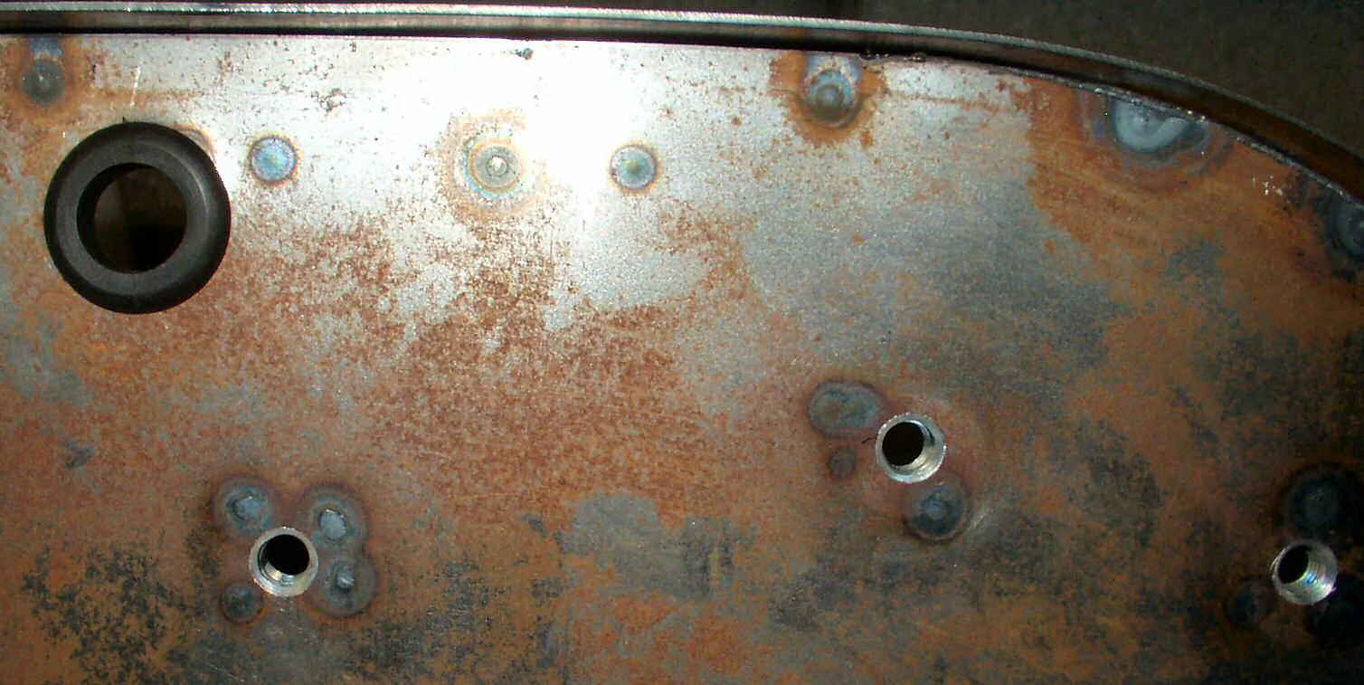
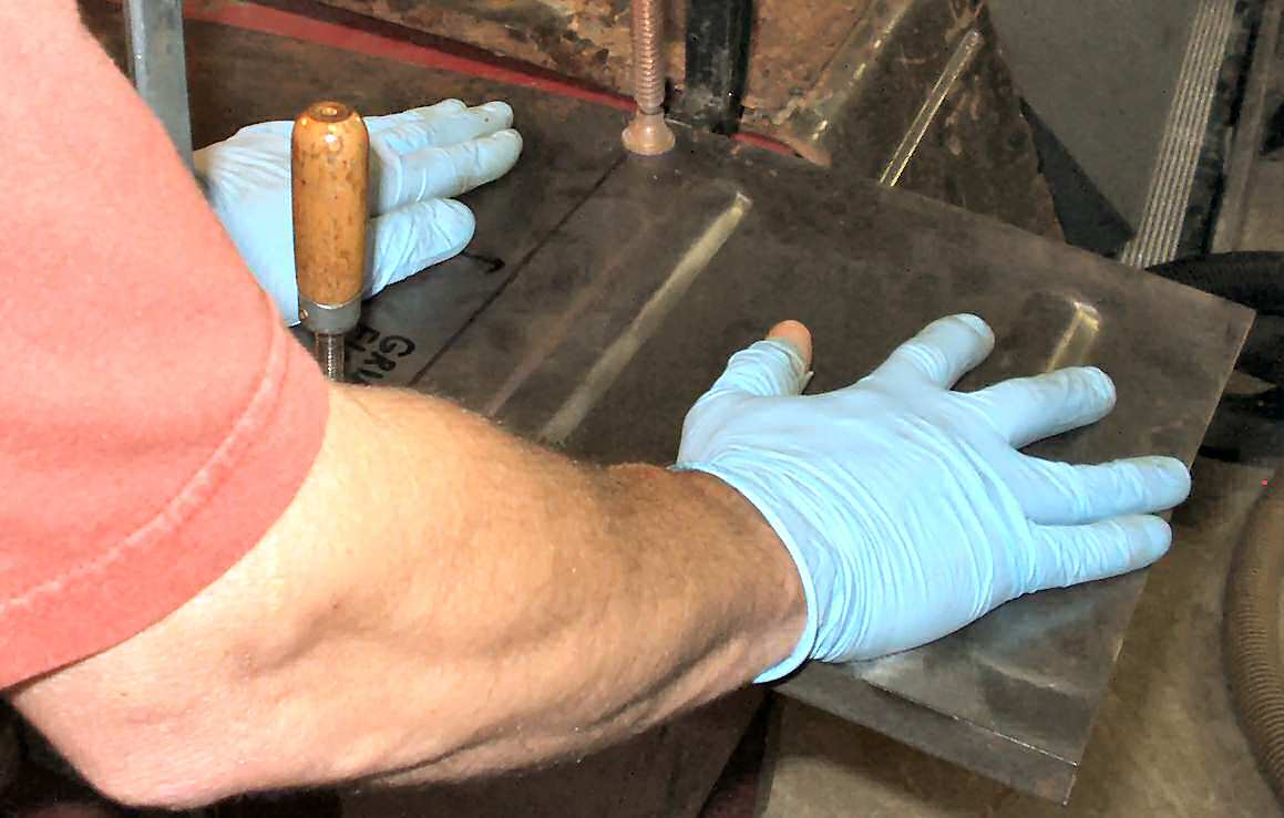
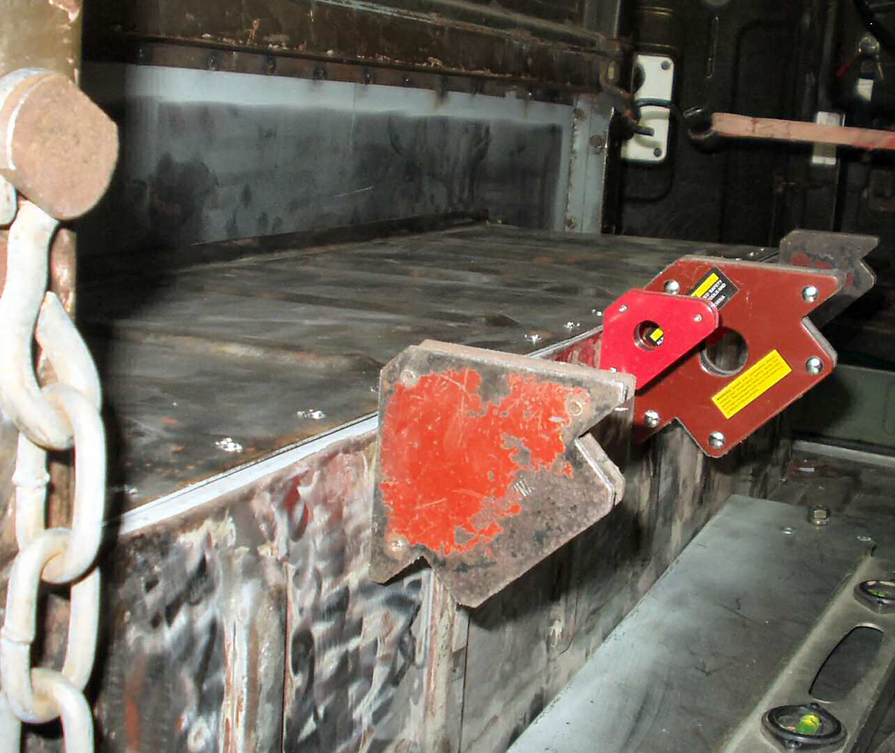
Now I could start adding the welded on nuts to the bottom of the wheel well tops for the soft top bows, rear jump seats, and jack tool clips. I started by laying the old top on top of the new top and used welding magnets to align them. See Fig. 15. Then using my new favorite tool the transfer punch, I marked the holes. After drilling them out to the proper size I threaded nuts on tight (See Fig. 16. ) and tack welded them into place. Next I used a 1/2" conduit knockout to punch a hole for the wiring grommet. See Fig. 17. This actually makes a 7/8" hole and I had a box of grommets from Harbor Freight that had 7/8" grommets in it. Fig 18 shows the finished top ready to de-rust.
Fig. 19 Taping to Prime Edge Top |
Fig. 20 Drilled Edge Side by Side |
Fig. 21 Primed edge on Side |
Fig. 22 Marked and Drilled |
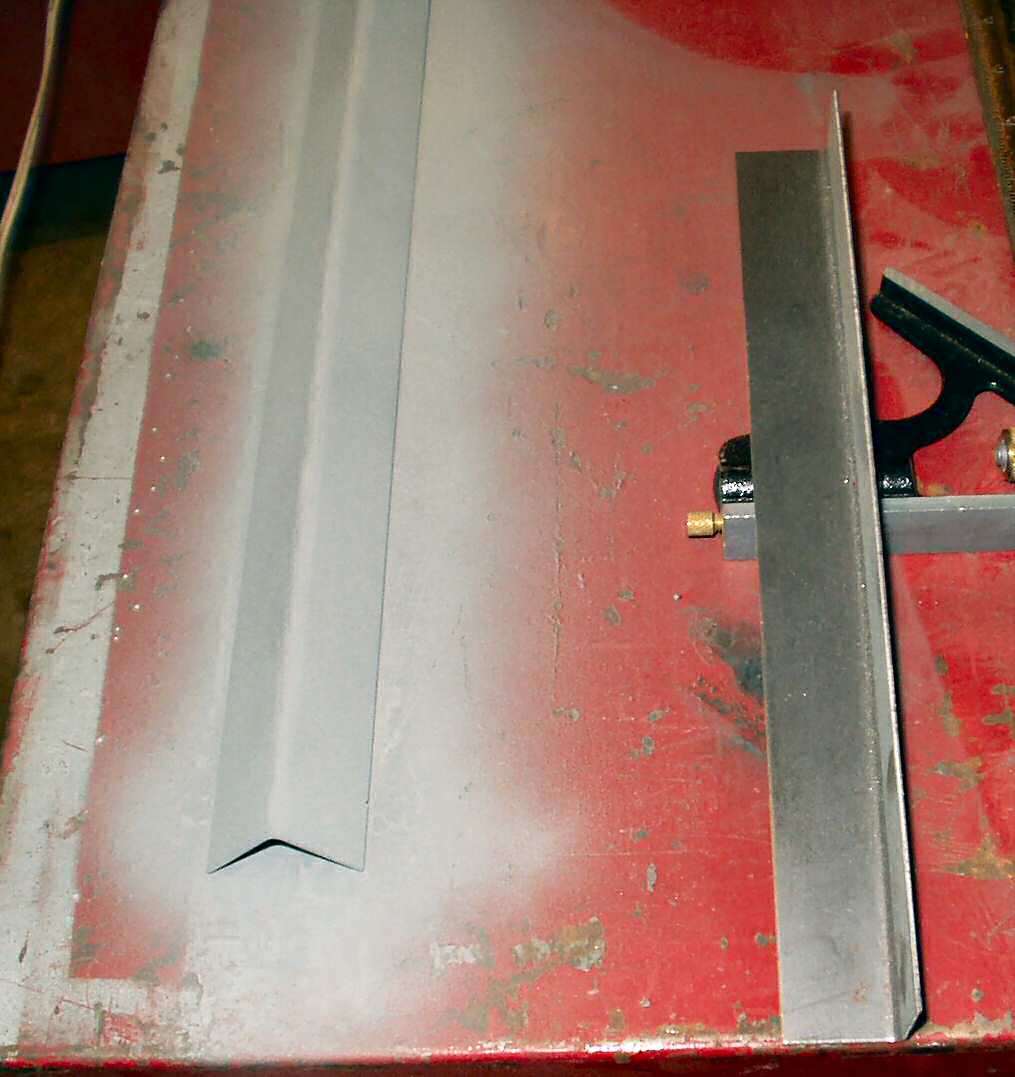
Fig.23 Primed Angle Support
|
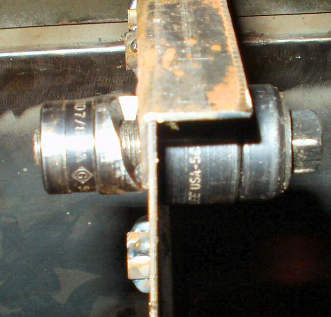
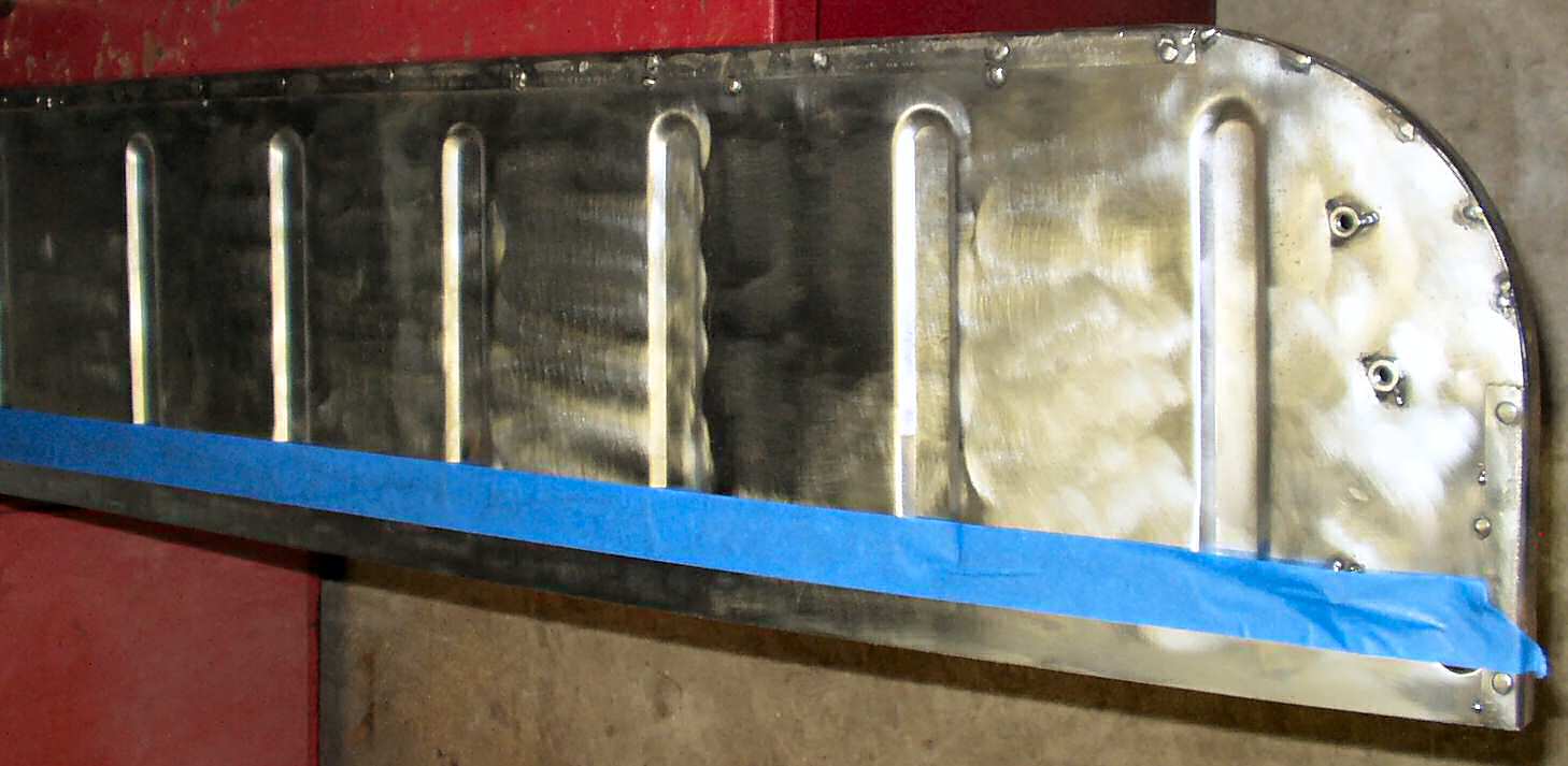
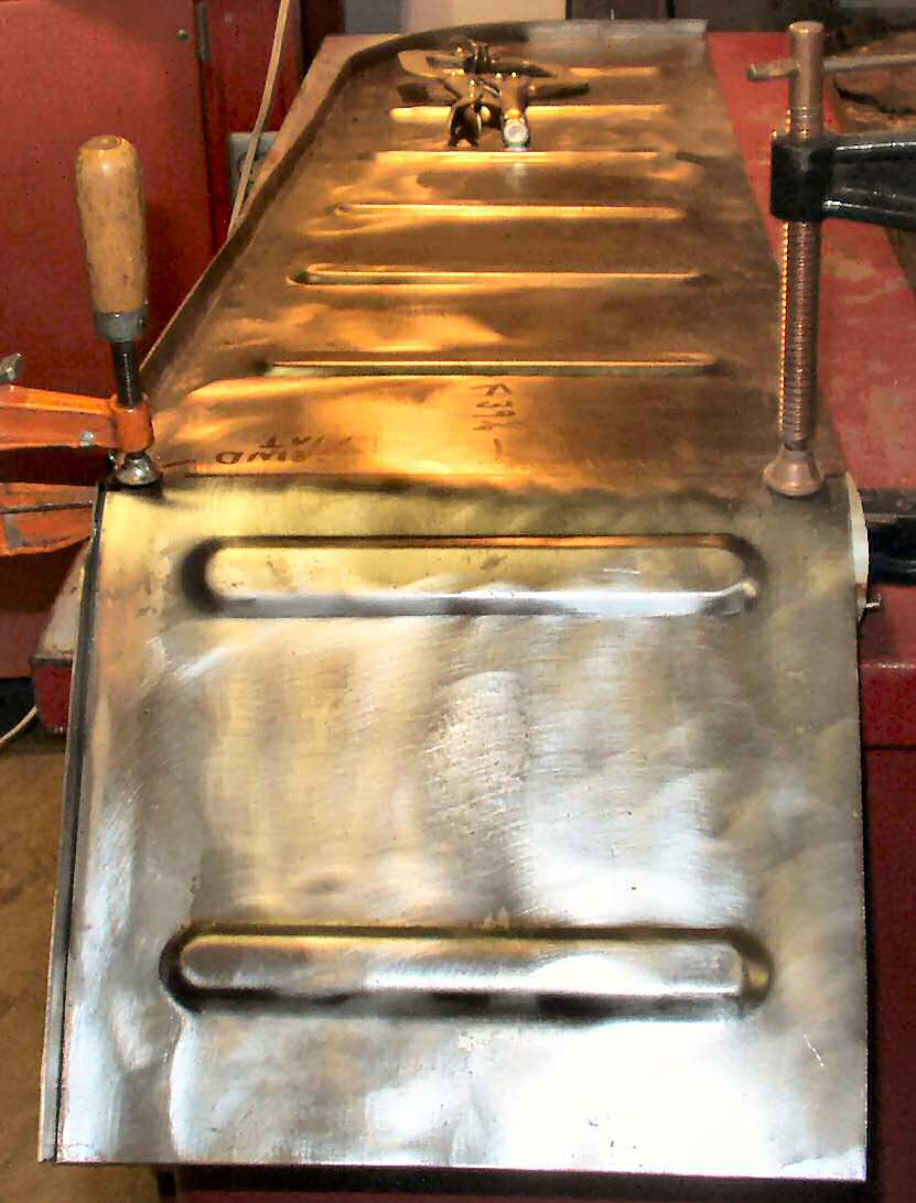
After de-rusting I ran a wire brush over it then taped the edge that will mount to the angle support so I could prime it with galvanizing primer. See Fig. 19. I then used a square and a permanent marker and drew a line in the center of where the angle support will be then used a ruler to mark the line every two inches. I drilled a 1/8" hole at each mark then came back and enlarged it to a 1/4" hole so I could plug weld. See Fig. 20 for drilled holes and a comparison to the old top. Next I did the same thing to the wheel well side. Primed, marked and drilled. See Fig. 21-22. Last I primed both edges of the support piece. See Fig. 23.
Fig. 24 Straightening Bar On Side Ready to Weld |
Fig. 25 Support Welded On |
Fig. 26 Checking fit and clearance |
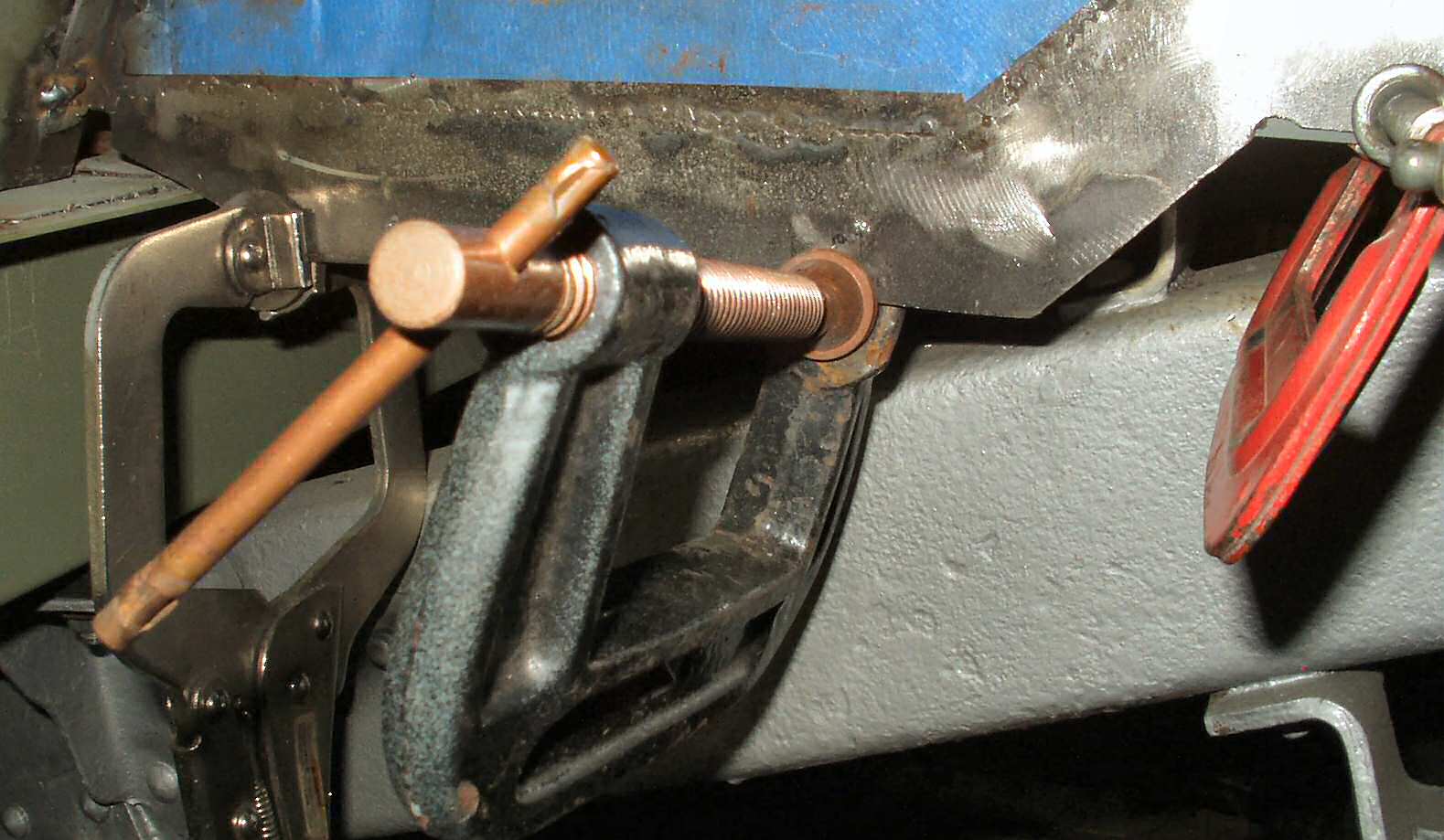
Now I could weld on the support piece for the wheel well top. This is just a 3/4" x 3/4" x 38" 16 ga bent into a 90 degree. I clamped it to the wheel well side using a piece of 3/4" square bar stock to ensure the edge was straight and to act as a heat sink to keep the thin metals from warping. See Fig. 24. I plug welded the piece working back and forth to minimize the heat build up. See Fig. 25. Then I tacked the bar to the support so I could remove the clamps. I trimmed the extra support sticking out off then mounted the side panel in the truck using clamps. Now I could start checking to see just how good I measured for the cargo floor and quarter panels! See Fig. 26. Wow! Everything lined up very well! I was impressed with myself! :-)
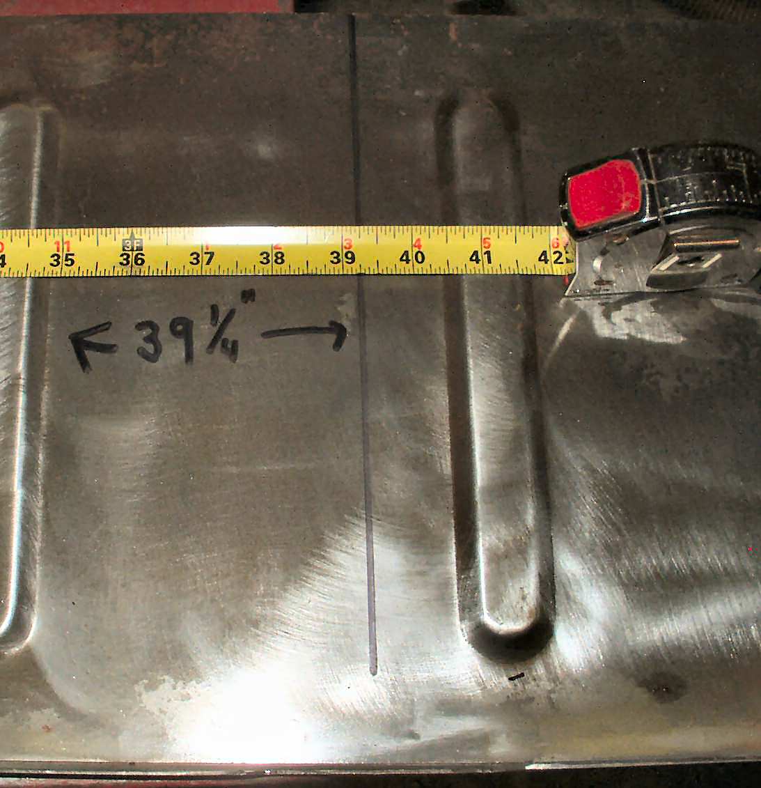
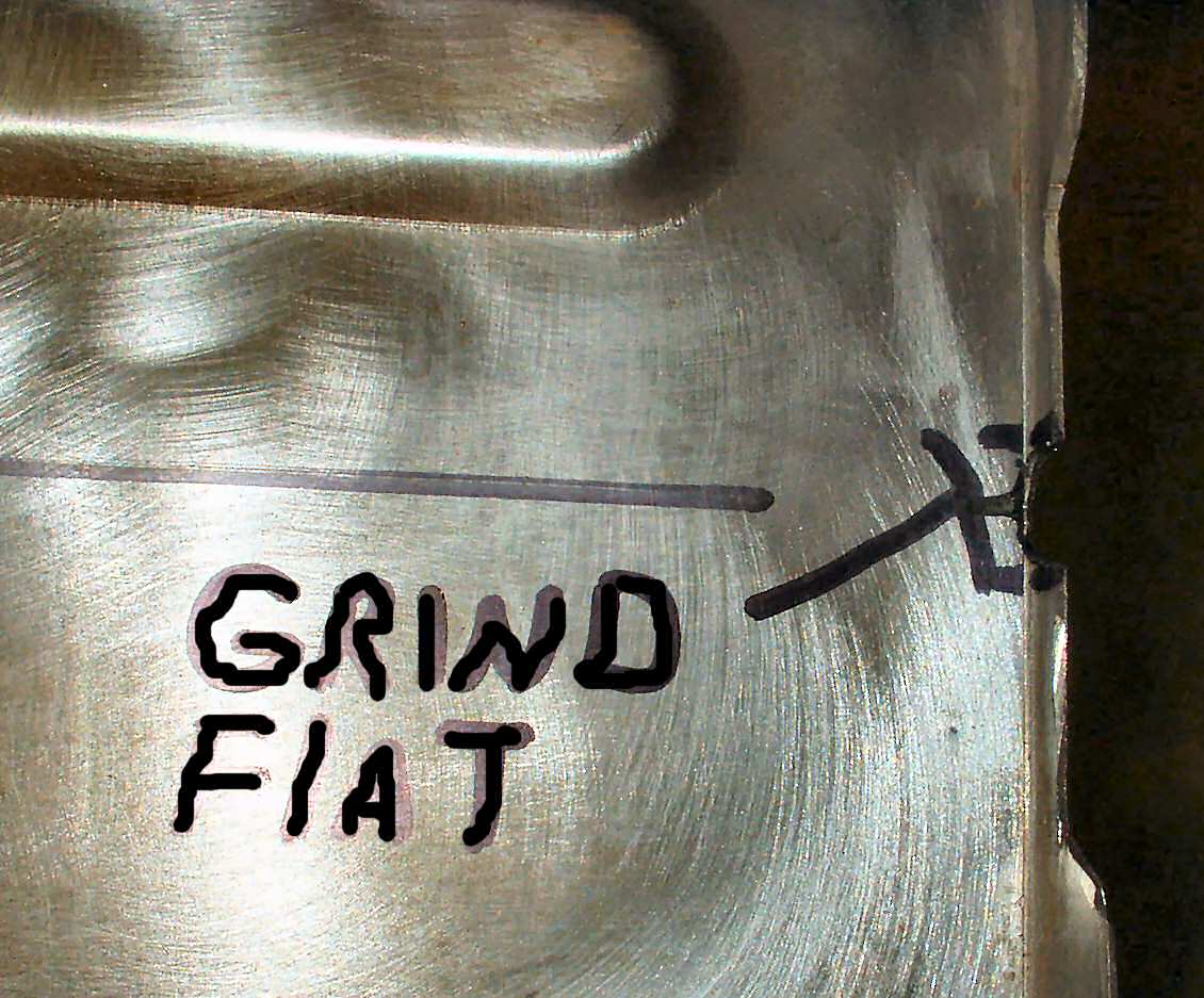
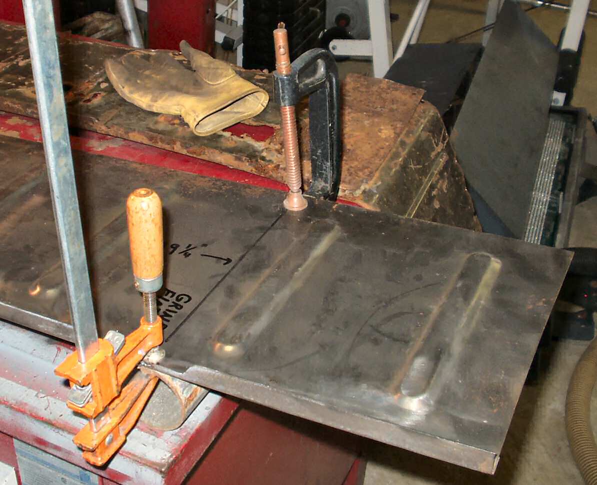
Fig. 27 Marked 39 1/2" Bend Line |
Fig. 27A Grind Edge Flat |
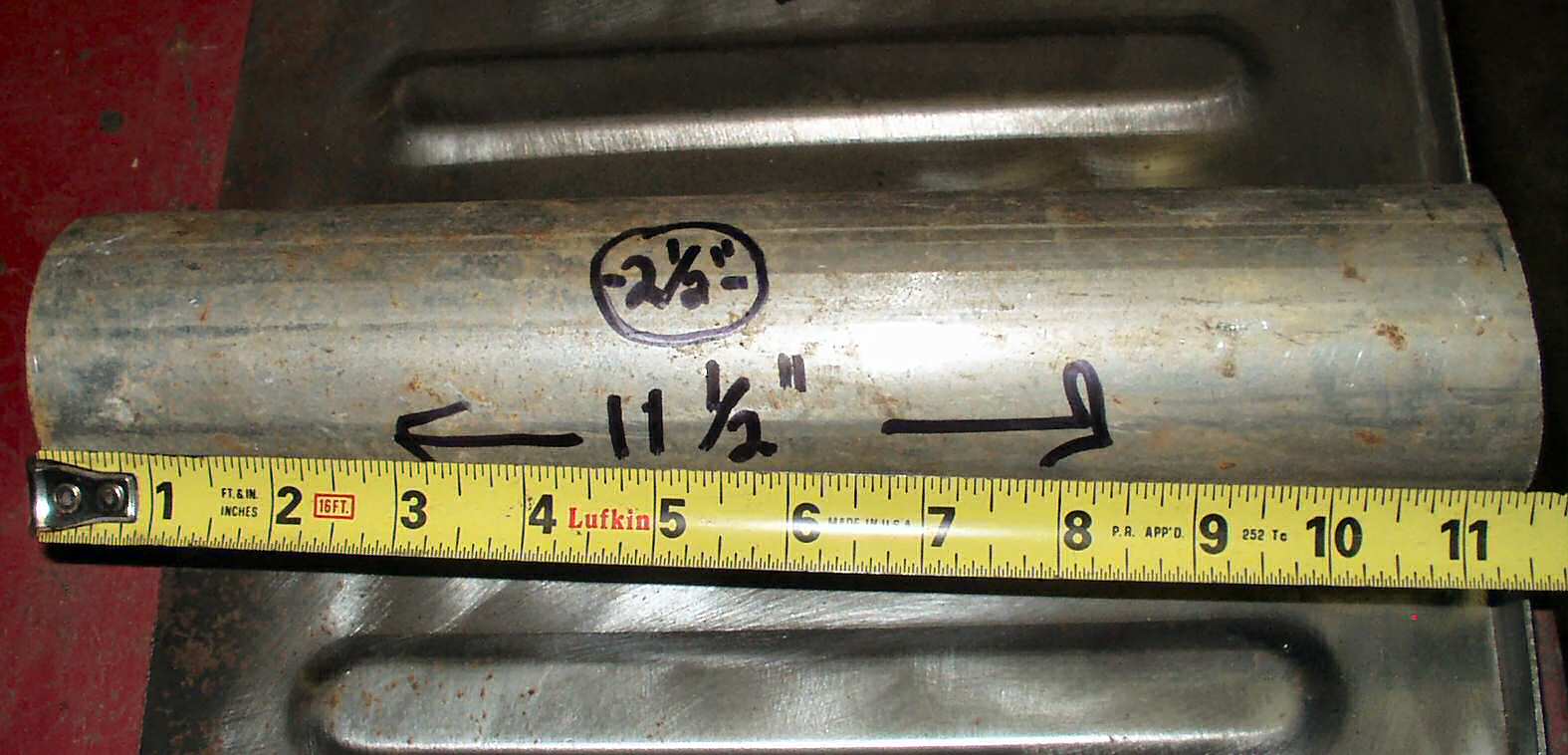
Fig. 28 Cutting Pipe to Size |
Ok , so lets move on to actually attaching the wheel well top and making the dreaded bend in the end to match the stock one...
Use a tape measure and measure the top on the edge that sits on top of the wheel edge vertical side panel. Measure 39 1/2" and make a mark. Use a straight edge to mark all the way across as shown in Fig. 27. Looking at Fig. 27A for reference grind down any flange that may be sticking above the top. If you don't it will not bend correctly!!!
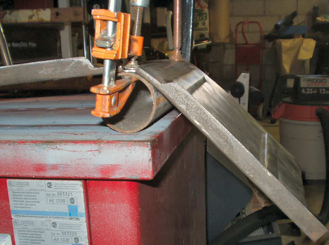
Now cut a piece of at least 2 1/2" diameter pipe about 12 1/2" long. The pipe can be made from anything. PVC, steel, wood doesn't matter. I used a section of electrical conduit left over from another project. See Fig 28.
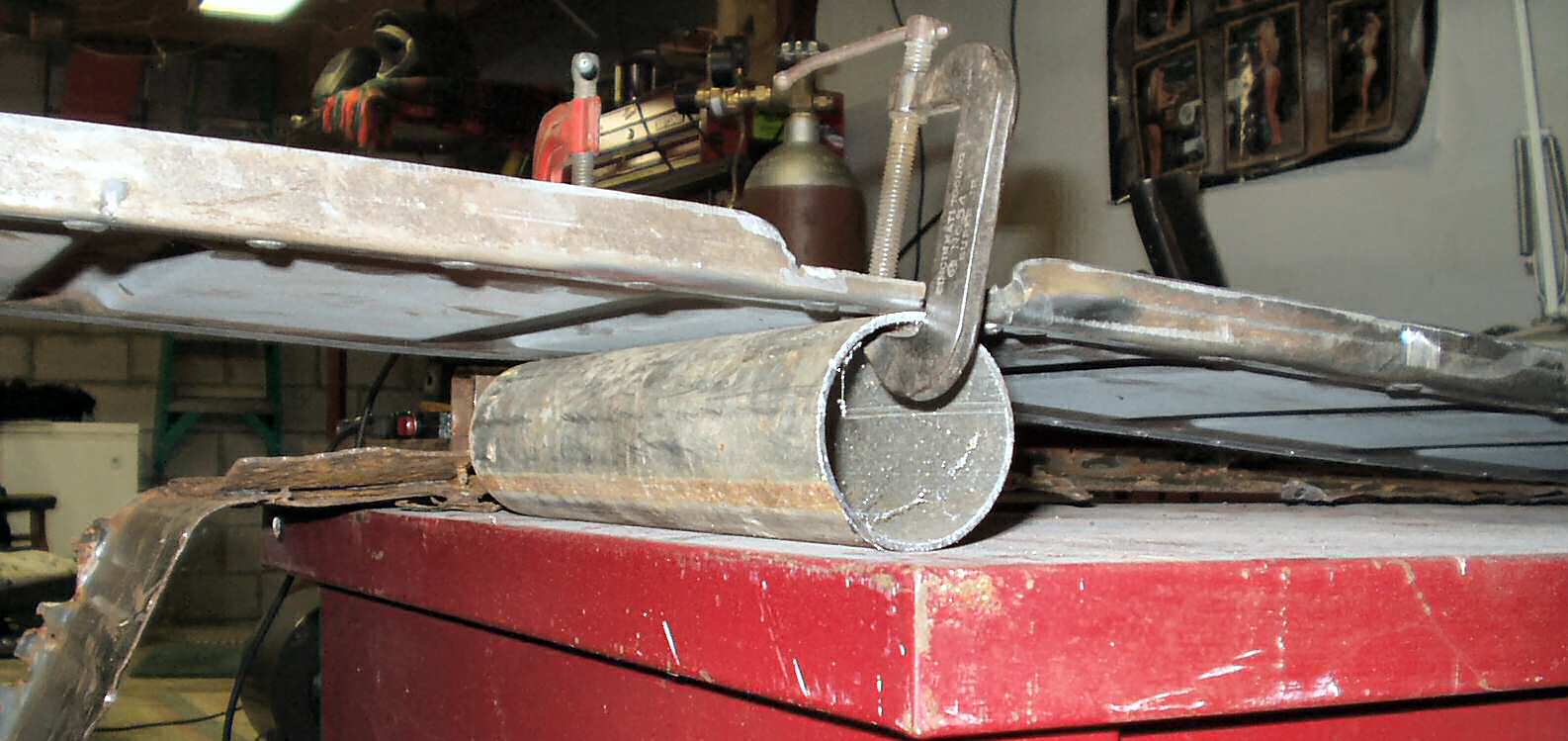
Fig. 29 2.5" Pipe Clamped to Bend Line |
Fig. 30 Bending |
Fig. 31 Close! |
Clamp the piece of pipe under the wheel well top so that the center of the pipe is directly under the line you just drew. See Fig. 29. Set this on the edge of a sturdy table, place your hands on each side of the line and start applying downward pressure on the short end. See Fig. 30. It actually bends easily at first then gets harder as you get closer to the proper angle. Make sure to keep your hands as close to the pipe as is feasible so that the pipe forms the proper radius..
Fig. 32 Comparing the bend to Stock |
Overall View |
Fig. 33 Test Fitting in Truck
|
Fig. 34 Test Fitting Bend |
Use the old wheel well top as a guide to see when you have the bend correct. See Fig. 32. Now take it to the truck and place it on top of the side panel to check the fit and the bend. Don't panic when nothing appears to line up! See Fig. 33-34.
Fig. 35 Clamping the top for fitting |
Fig. 36 Clamp through Side |
Fig. 37 Clamping the side panel |
Fig. 38 Clamping the front edge |
Fig. 39 Lining up the side and top using welding magnets |
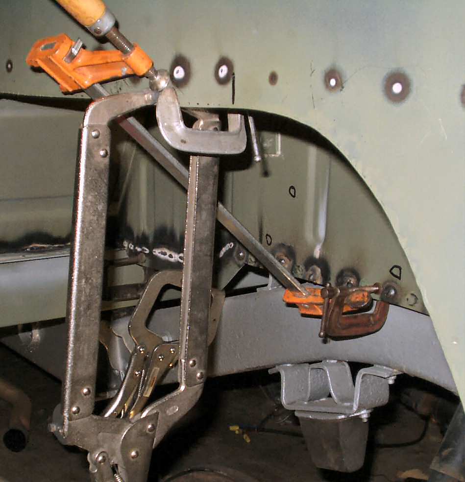
Get several clamps and clamp the top against the quarter panel. A small welding clamp will fit through the reverse light hole and a bigger one will fit through the side marker hole. A LARGE welding clamp can be used to clamp the front edge. See Fig. 35-38. This is the moment when you will find any mistakes you made making quarter panels, cargo floor, mid bed or center channel! I was off a bit on the width of my cargo floor. It's too wide by about 1/8". Fortunately the side panels and quarters have lots of 'play' so when I clamped it up it looked normal!
Test fitting drivers side Looking GOOD! |
Be aware that that the Real Steel tops DO NOT provide enough length to make the factory bend at the end, the one that folds back under and mates with the center channel end pieces. It's too short by about 1". So where the top meets the end piece I will have to weld it all the way across. Still not impressed with these... Anyway now is the time to find and fix any thing that is in the way of the panel fitting correctly. I had to cut a slot in the tail gate chain support to allow the top to slide in about 1/4". I also found a couple of places where I had cut too much off when fitting the side panel to my custom rear sill. You will have your own issues....
Fig. 40 Clamped for Welding
|
Fig. 41 Clamping Front Edge to Weld |
Ok after all the fitting and fixing pull the top and side panel out take them to a bench and clamp it as shown it Fig. 40. I gotta confess that I did not do this at first. I tried to plug weld it while it was in the truck. I was excited about getting all of this to line up and got in a hurry. The result is the plug welds warped the metal causing it to not lay perfectly flat against the angle support. When I finally noticed it, it was too late... So don't do that! Fig. 41 shows how to clamp the front edge. I was pleased with the way the panel fit here. I did use a flap wheel on the edge after welding it in to blend the two edges together. When I put the Durabak on it will look good.
Fig. 42 Original Wire Clamp |
Fig. 43 Making new wiring clamp |
Fig. 44 Welded on
|
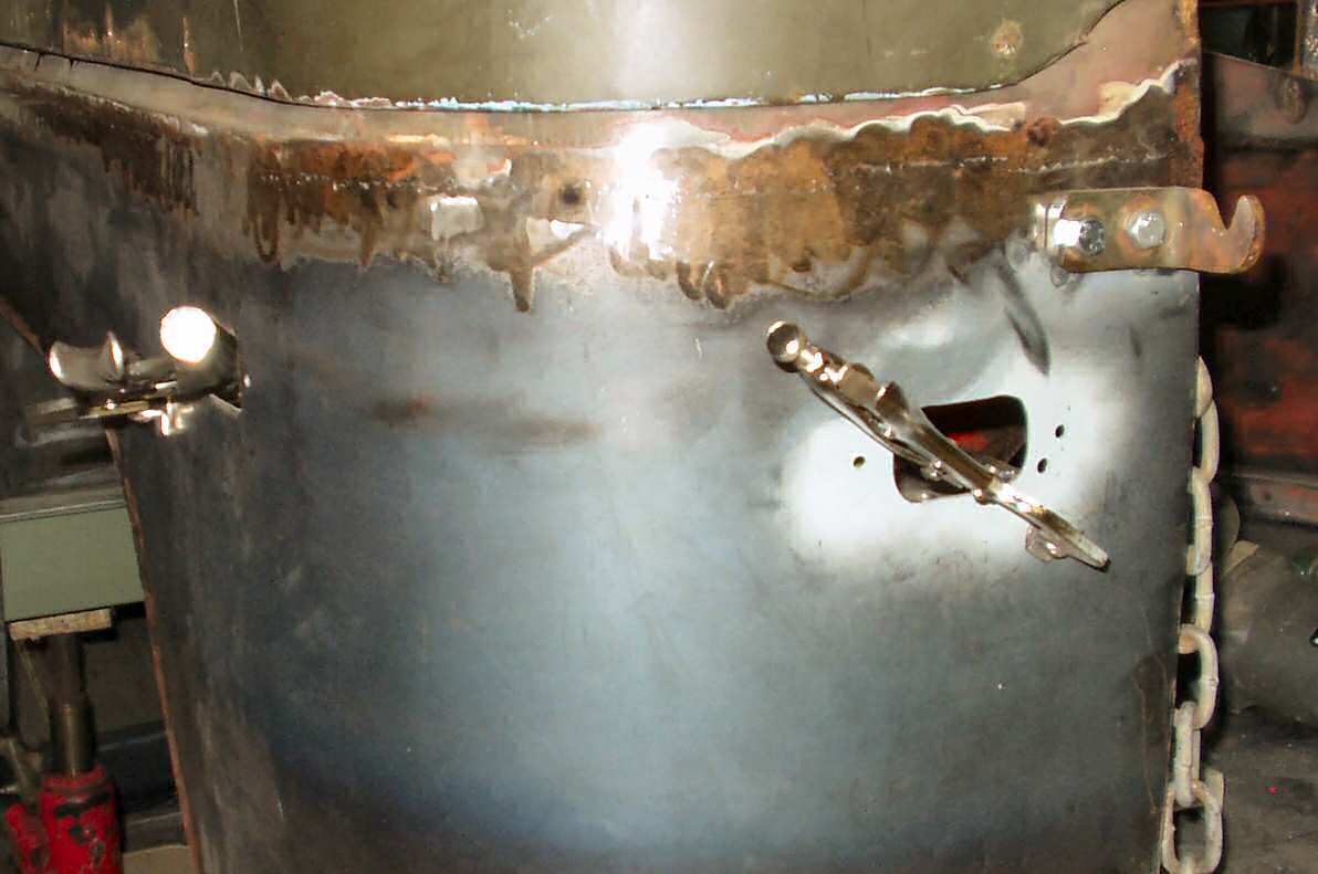
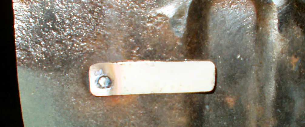
Next I started working on all the other things I had to add to the wheel well. My 71 had a metal strip spot welded to the end of the side panel to hold the wires for the backup light in place. See Fig. 42. I noticed it was about to break so drilled out the spot weld to remove it. Of course it did break then! I cut a section from a computer case allowing a bit of extra length to ensure it would hold the wiring loom then plug welded it in place. See Fig. 43-44. In case you are wondering I plan on going over this one last time with the wire brush before priming it with a self etching primer. The whole thing will eventually get Durabak applied.
Whew! This is a long page! Next on the list: Passenger Side, Mounting the jack tool clips.
Fig. 45 Aligning Clips |
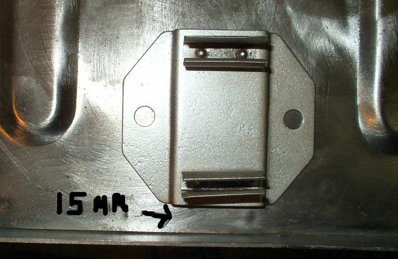
Fig. 46 Clip Spacing 15mm |
Fig. 47 Tool Clip Nuts Welded On & Primed |
Space the clips as shown in Fig. 45-46. The clip closest to the rear is centered and the clip closest to the front is about 15mm from the rear raised ridge. They are both 15mm from the edge flange. Mark your holes then drill them out with a 11/64th drill bit. Now get 4 10mm x 1.0 thread pitch nuts and 4 10mm x 1.0 x 25mm bolts. Thread the nuts barely onto the end of the nuts then spray the nuts with a galvanizing primer. After they dry put the bolts through the wheel well top, thread the nuts on and weld the nuts in place. See Fig. 47.
Fig. 48 Mystery Mount |
Well this gets us to the mystery mount. On my drivers side wheel well top were two 4mm x 1.0 screws threaded into a spot welded backing plate. I have no idea what this was for but I removed it, de-rusted it, primed it and welded it on in the same spot. It was centered on the wheel well. See Fig. 48.
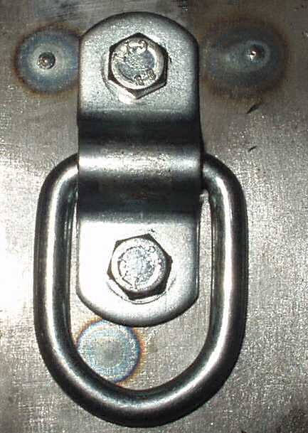
Fig. 48A D-Rings |
Fig. 48B Backing Plates and D-Rings |
Fig. 48C
|
Fig. 48D In Place on Wheel Well Side |
Since I have been reading about Cruisers for the last 3 years and have hundreds of pics from the web I decided to go through all this stuff and see if I could get some ideas about tying stuff down in the cargo area. I saw several good ways to do it but while in my favorite hardware store recently I ran across these cheap ($1.49 each) small D-rings. See Fig. 48A. I got 4 of them and played around a bit with placement. I finally decided where to mount them and made up some backing plates from 1/8" strap to which I welded some 10mm x 1.0 nuts. See Fig. 48B. These backing plates were then welded to the inside of the wheel wells. See Fig. 48C. Fig. 48D shows where on the wheel well side I mounted them.
Now I can bolt the D-rings on when needed or remove them if I need to haul something that might hit them. I also plan on using them to hold other things as I come up with them. I will powder coat the D-rings and brackets Star Dust Silver then dip the rings in Plasticote black so they won't rattle so badly.
Fig. 49 Test Fitting Seat |
Fig. 50 Marking Hole |
Fig. 51 Backing Plates |
Back at the beginning when I was marking the holes for the jump seats I found that only the one hole could be marked! The others were rusted out and long gone... So in order to get the other two holes made I had to clamp the wheel well in place then fit the seat in place. See Fig. 49. This revealed that my wheel wells on both sides were too tall. The seat brackets would not bolt up. I had to trim the wheel well sides to lower them down a bit. (Be advised that by mounting the wheel wells higher you can gain space for larger tires!) I elected to mount them in the stock location. Once I got the height correct I bolted the back brackets in place and put a bolt in the rear wheel well nut. Now I could mark the locations for the remaining two holes. I used the hole marking tool to do this See Fig. 50. After these were marked I removed the wheel wells one last time. Since I will have seat belts attached to these I made up some backing plates from 1/4" plate I had and drilled and tapped them for 10mm x 1.25 bolts. See Fig. 51. Next, you know this routine by heart, : De-rust, wire wheel, prime with galvanizing -weld thru primer and weld in place, wire wheel welding slag and prime again. These wheel wells are getting heavy! Repeat for the passenger side.
Fig. 49 Marking Primer line |
Fig. 50 Ready to Prime |
Fig. 51 Primed |
One more thing. Before you take the wheels wells out for the last fitting, use a marker and draw a line around the top edge of the top panel as shown in Fig. 49. Now remove the panel and grind off any primer, rust, paint or grunge about an inch below the line. Prime that area with a galvanizing primer. See Fig. 50-51. You want to keep the rust at bay as long as possible!
Fig. 52 Ready to Weld In |
Fig. 53 Plug Weld Holes |
Fig. 54 Primed Cargo Floor Edge |
Fig. 55 Lots-o-clamps! |
Fig. 56 Front Seam |
Fig. 57 Welded in Place! |
Prep the wheel well by priming anything you missed before. They should be pretty well primed by now. See Fig. 52. Drill a series of 1/4" or larger holes along the bottom edge so that you can plug weld in the lower edge to the cargo floor edge. Make sure that cargo floor edge is already primed. See Fig. 54. Now use a wire wheel and remove the primer along the OUTSIDE edge of the wheel well. This keeps the weld a bit cleaner so it doesn't pop as bad. You will reprime it later after removing the welding slag. You may want to consider undercoating the panels at this point. I still have to weld in the supports for the roll bar so I'll do that later.
Clamp the wheel well loosely and then re-mount the jump seat. The seat will help line up the panel properly. Once all the bolts are tight then clamp the panel in place as before and start tack welding it in place. If you don't have enough clamps then move your clamps for EACH weld so that you get the tightest possible seam. I tacked a couple on the bottom outside then the top inside then started working my way forward. To help pull the quarter tight against the wheel well top in the middle I used several clamps linked together. If your top is off this is not an issue. See Fig. 55. I finished welding the panel in by running a continuous weld seam tying the floor to the wheel well (no comments about my welding, I'm still learning!). See Fig. 56. Fig. 57 shows the drivers side welded in completely.
Fig. 58 Primed
|
Fig. 59 Lots of help... |
Fig. 60 Complete! |
Fig. 61 Primed & Welded
|
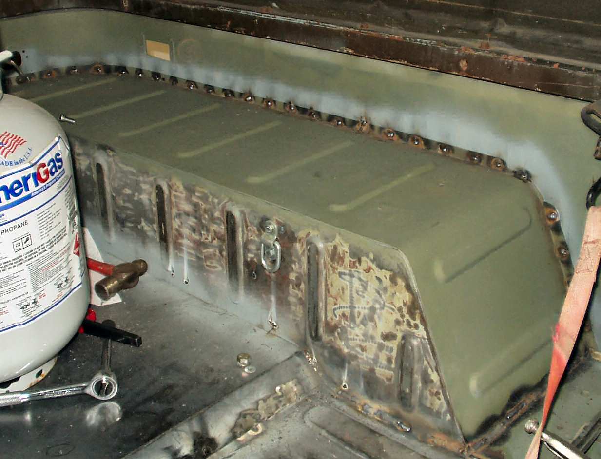
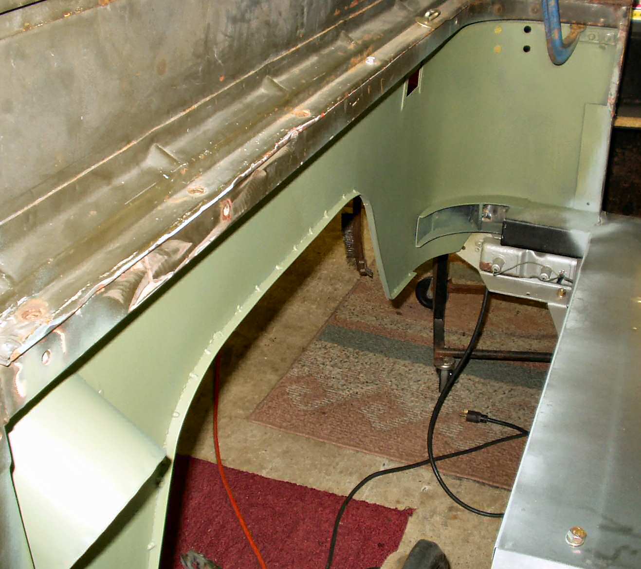
Here are a couple shots of the passenger side wheel well install. As you can see in Fig. 59 once the heater came on the 'help' took a break!
The passenger side has two 'extra' things to deal with. First the gas tank filler mount is in the way forcing you to have to fight to get the wheel well in place. Next is the top spare tire carrier backing plate. Since it fits over the wheel well top flange I could not put it back until the wheel well was tacked into place. After this was done (See Fig. 60) I welded that last piece in. See Fig. 61.
Well that completes the wheel well install.
Hosted by Global Software, Inc.
©1998 - 2023 Mark C. Baker Web Designer
Please: No part of this web site may be used without express permission... email mbaker@globalsoftware-inc.com for permission.