Fig. 3
Powder Coated Intake
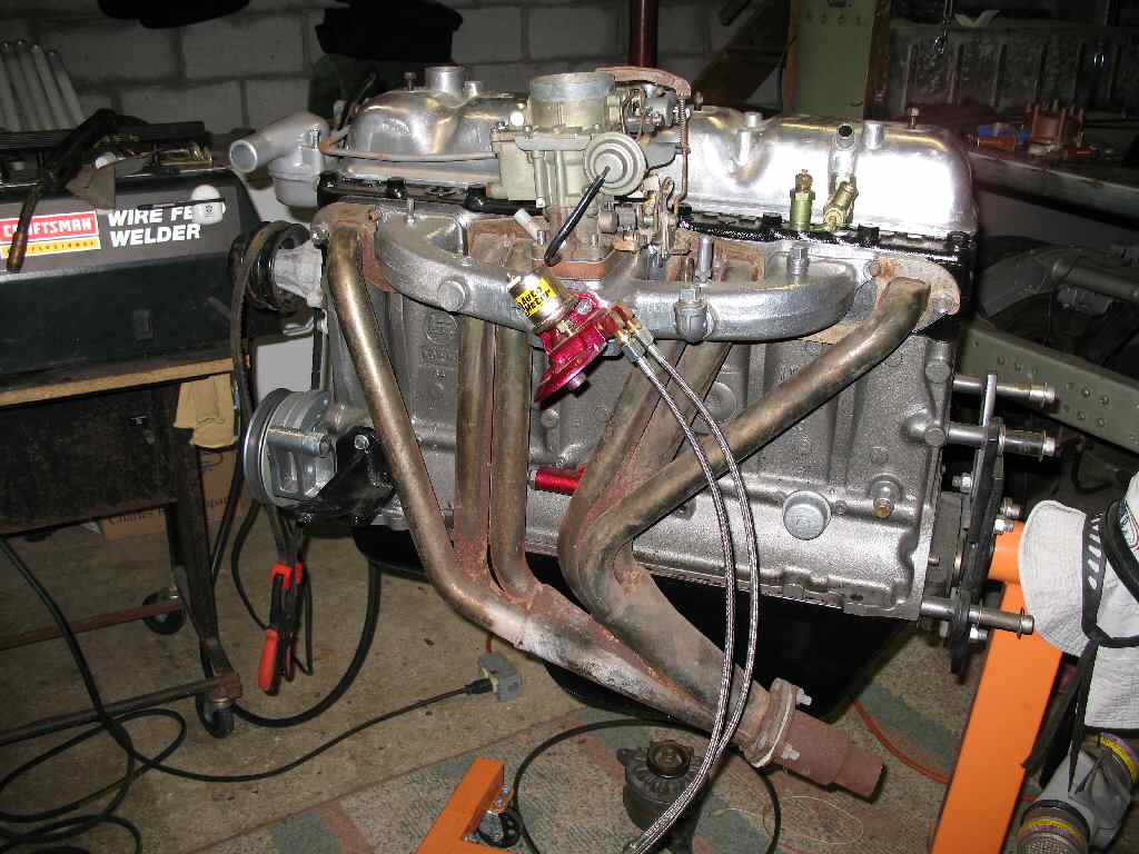
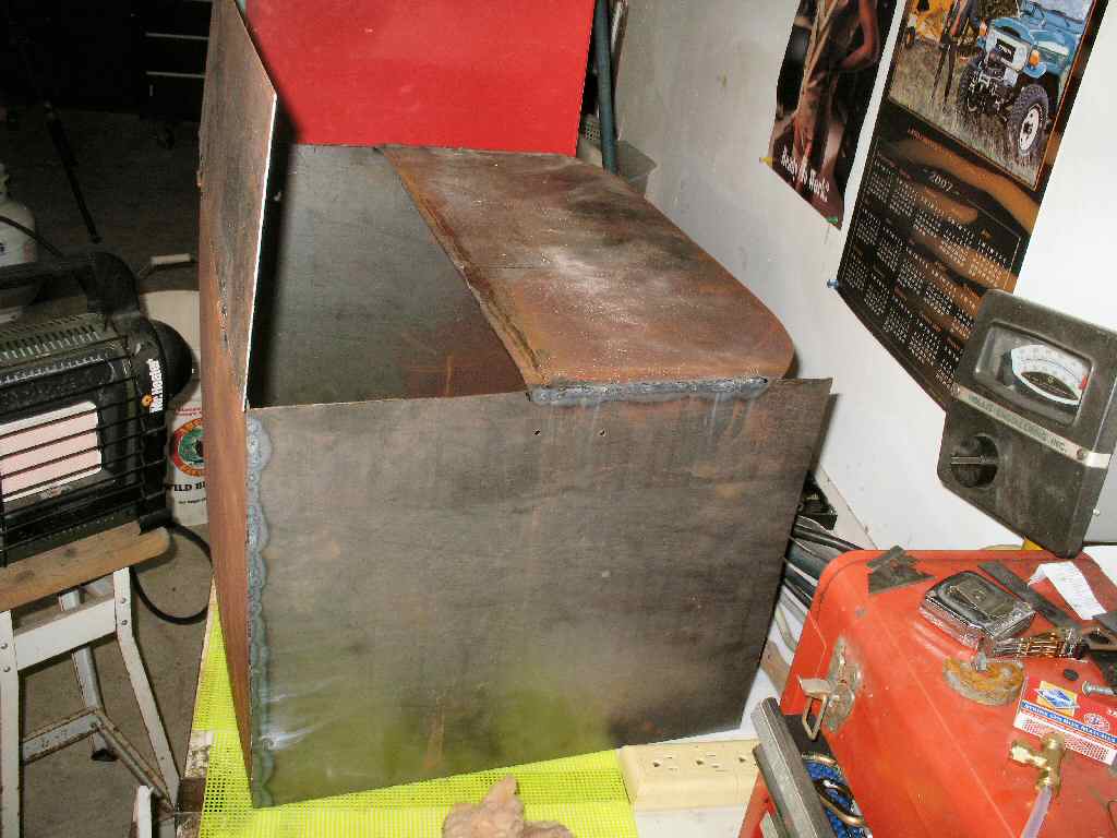
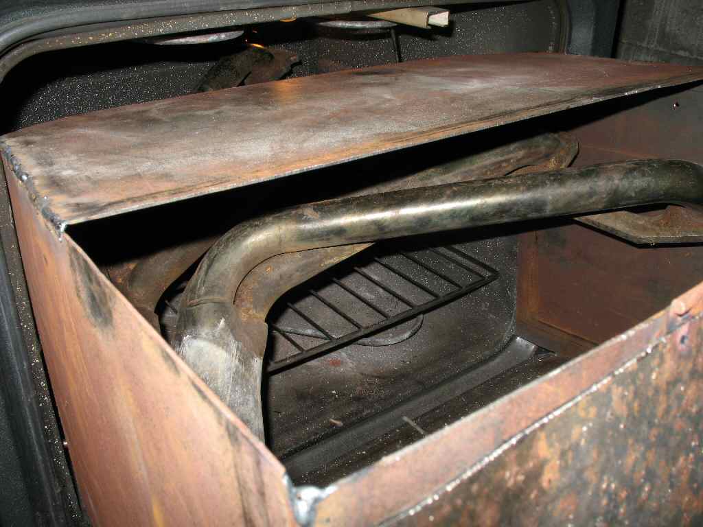
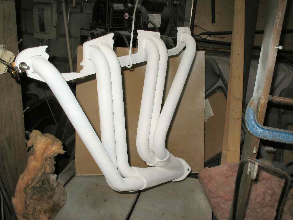
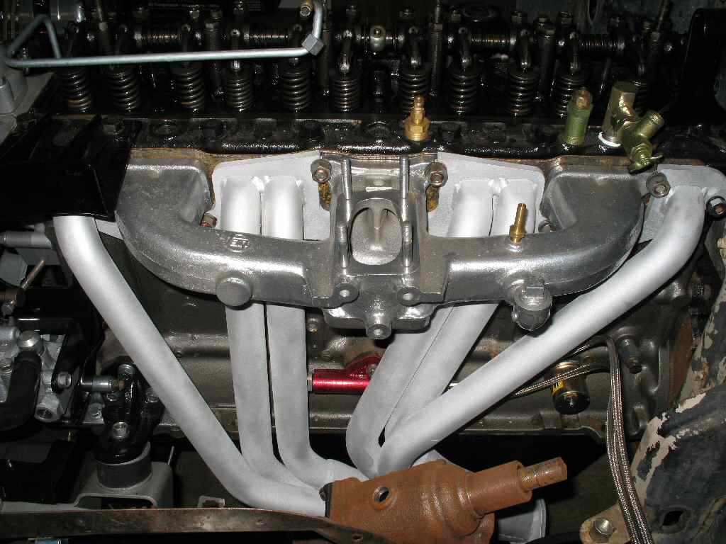
Fig. 4
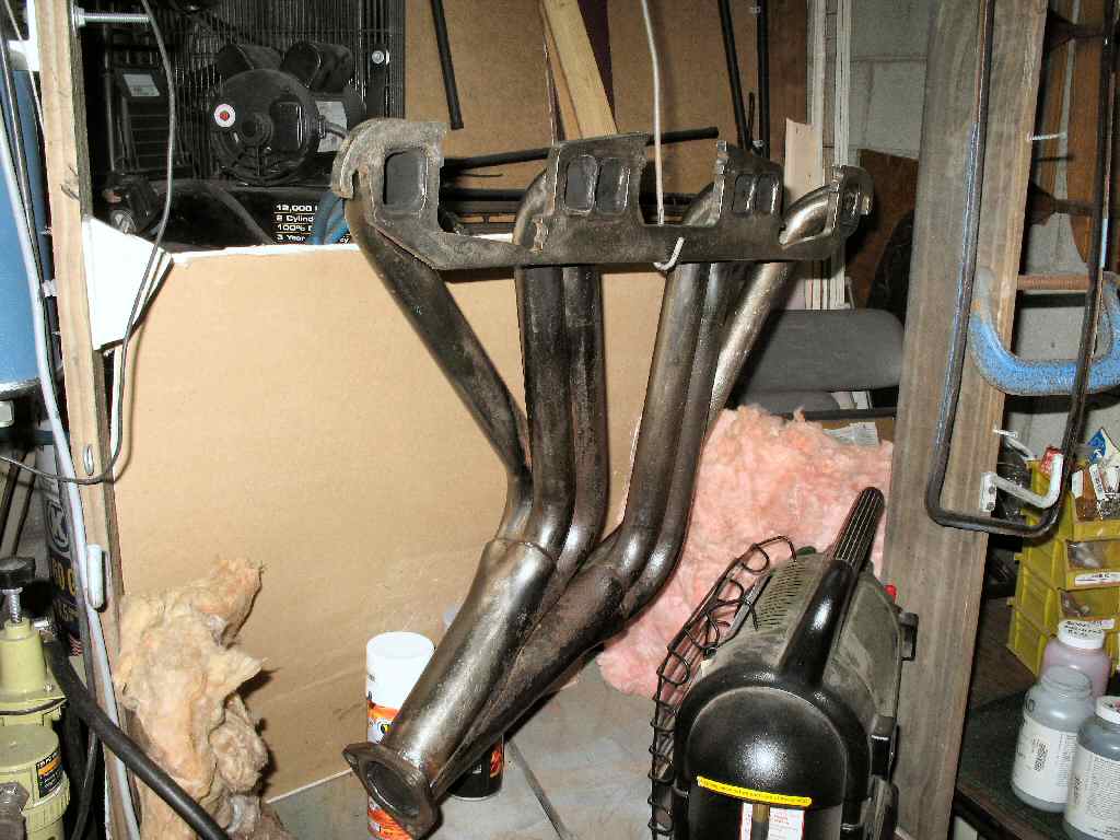
Test Fit Headers/Intake
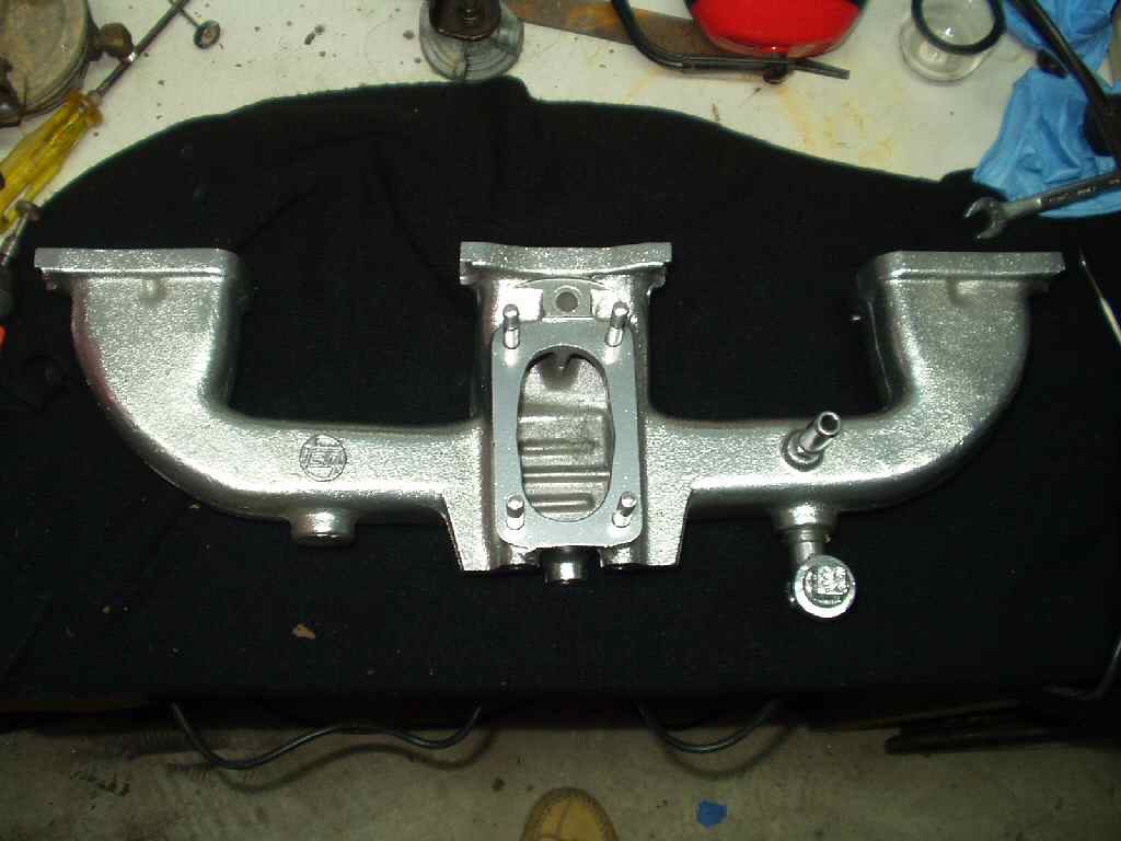
Fig. 3 Powder Coated Intake |
Fig. 4 Test Fit Headers/Intake |
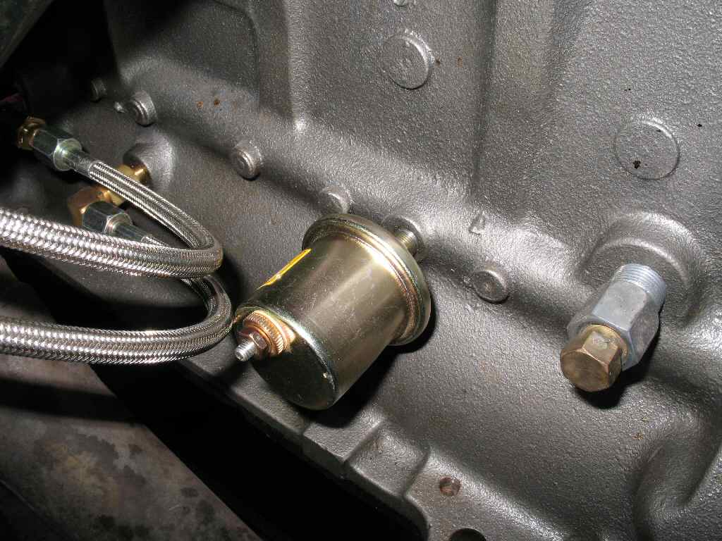
Fig. 8 Electric Sending Unit |
Fig. 9 Old Sending Unit |
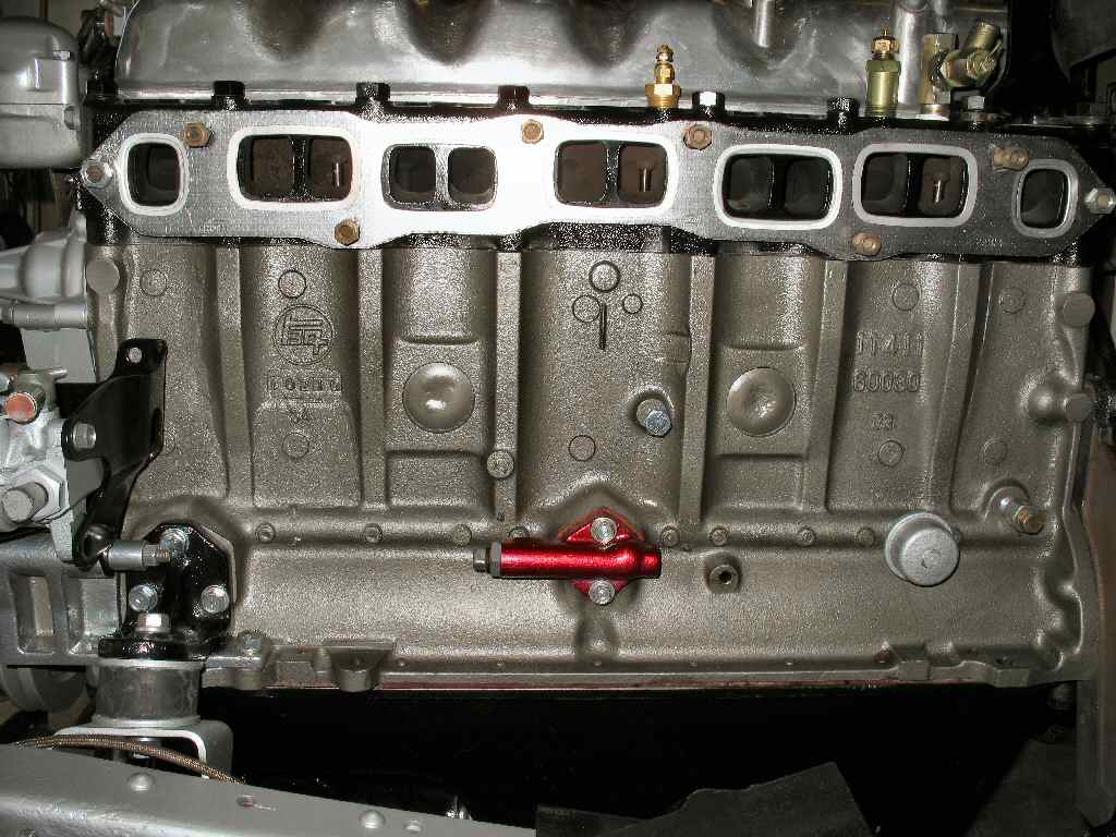
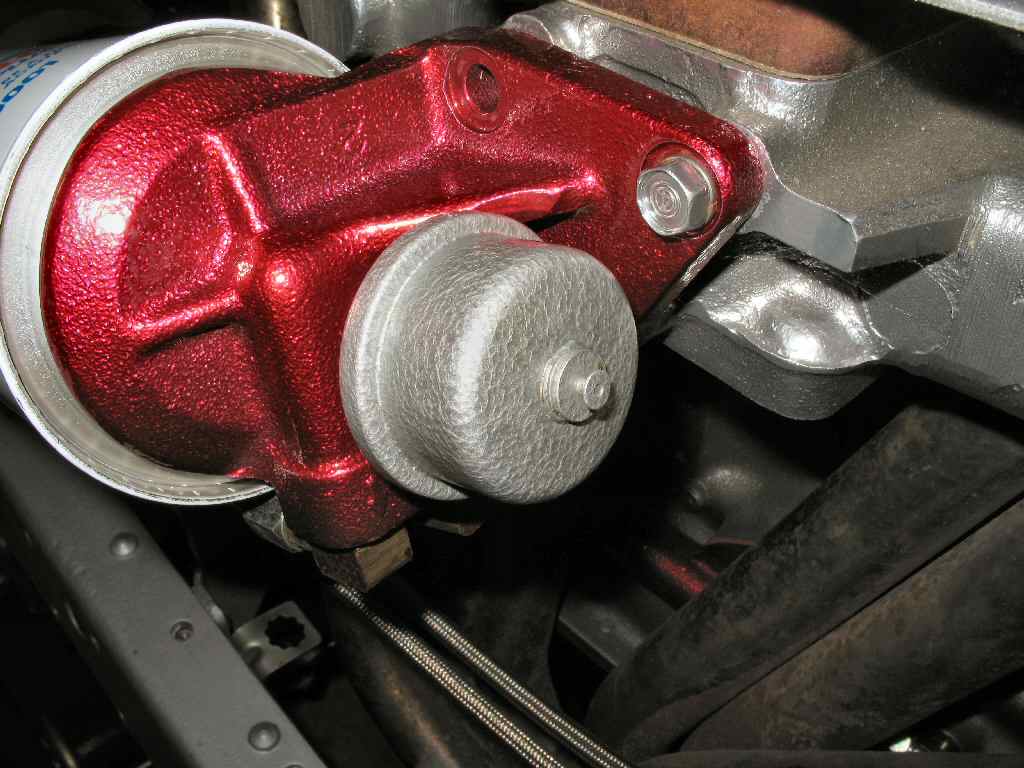
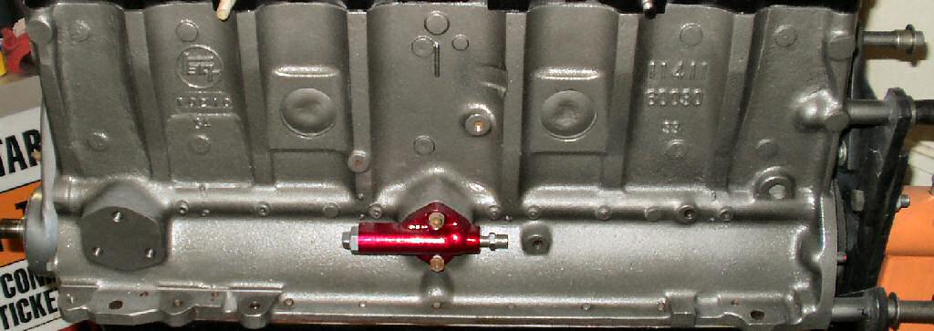
I started the passenger side re-assembly with the oil pressure regulator. See here for the disassembly and cleaning of this piece. I made a gasket, coated both sides with blue silicone and mounted it to the block with 2 8mm x 1.25 bolts. Note the orientation! See Fig. 1.
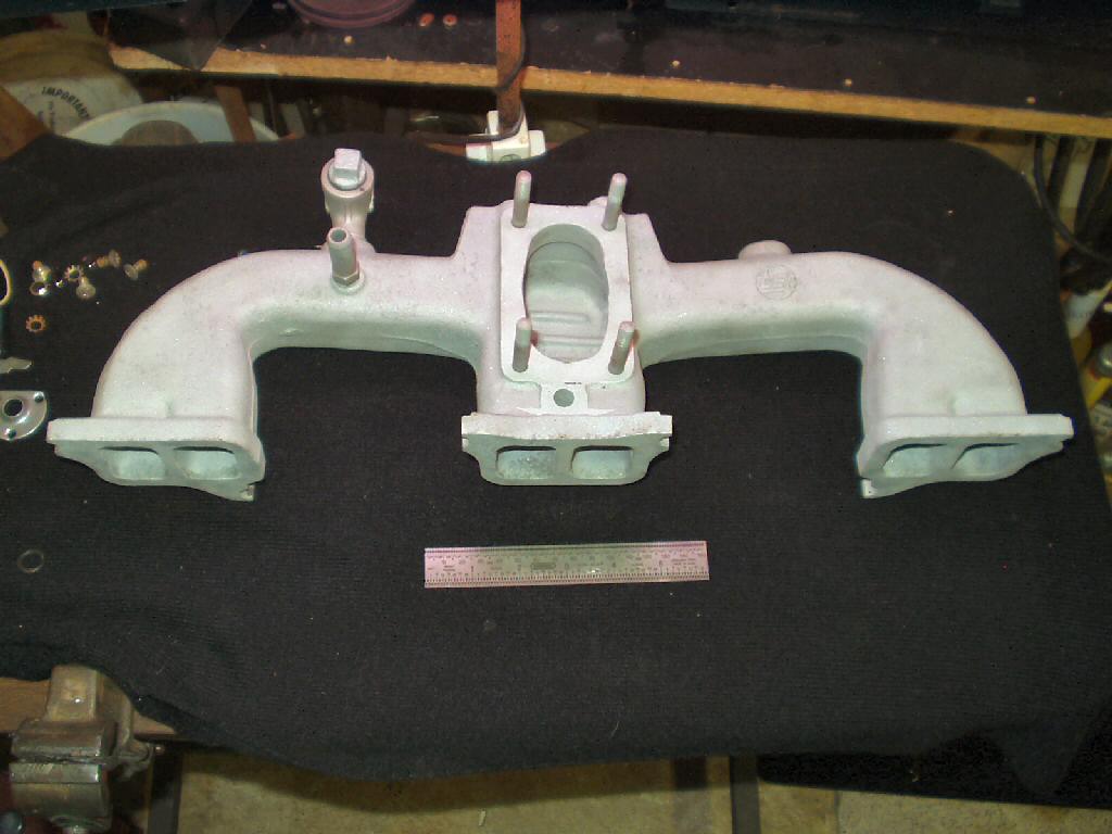
Ever wondered what a sand blasted intake manifold looks like? See Fig. 2. Fig. 3 shows what it looks like after powder coating it with extreme chrome.
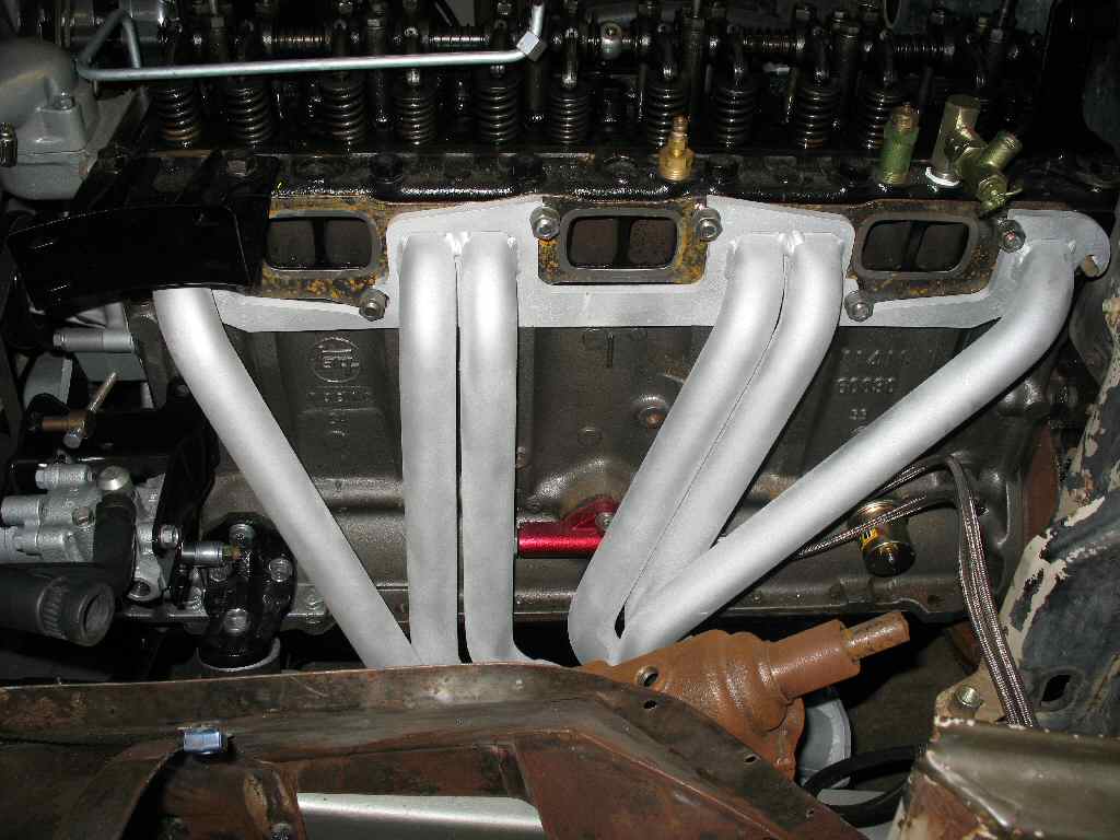
Now I could test fit the intake and headers. See Fig. 4. Everything looked OK, so I removed those pieces in preparation for installing the engine back in the frame. From this point on the engine is in the frame as parts were bolted on and tested.
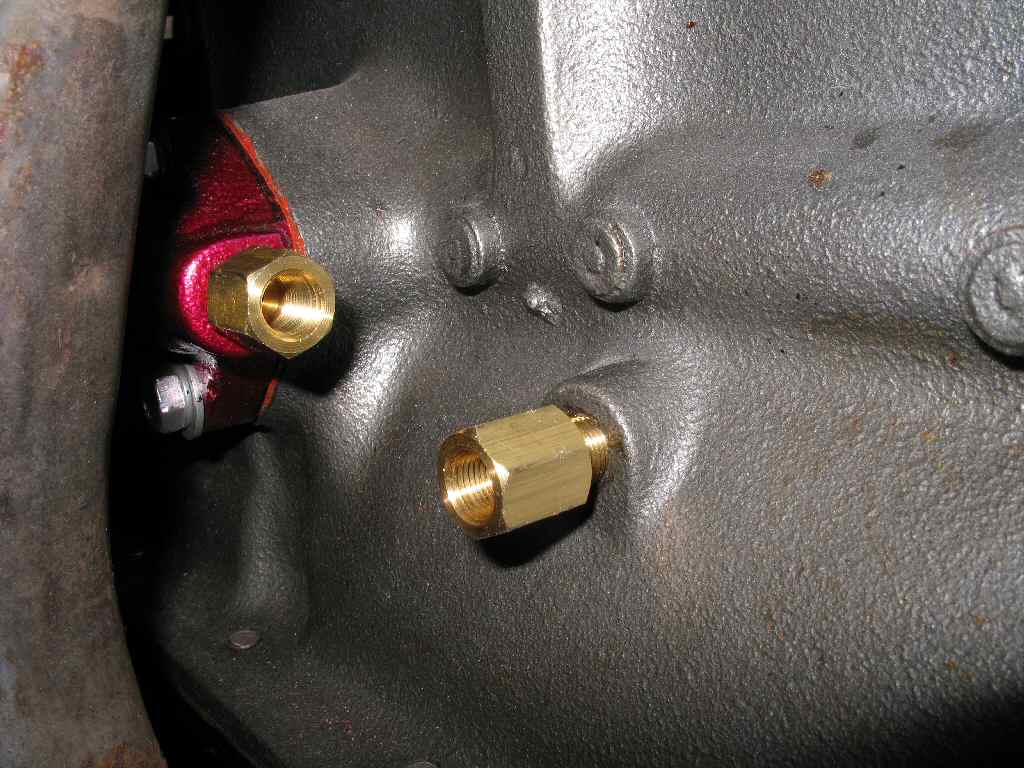
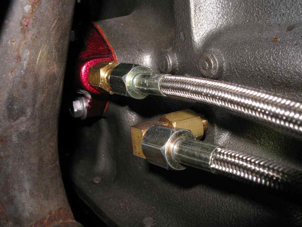
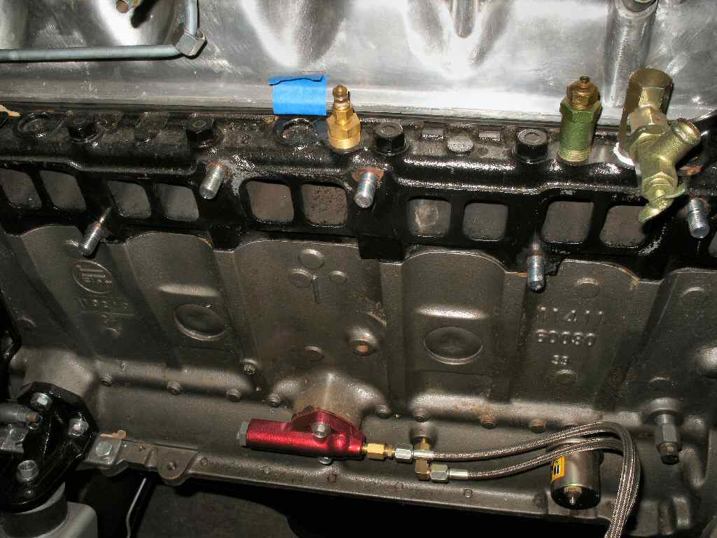
I had ordered a set of braided steel oil lines from SOR and had been assured they had the correct fittings to thread into my block. Yeah.. right... and 4 legged pigs can fly. What they shipped was two oil lines with standard JIC fittings and 1/8-27 NPT fittings for the block and oil filter housing. Everyone by now knows that ALL pipe fittings on a FJ40 are BSPT fittings (with the exception of the fuel hard line fittings.). So I had to order some 1/8-27 NPT to 1/8-28 BSPT adapters. I got two 90 degree male to female 1/8-27 NPT adapters and two straight 1/8-27 NPT to 1/8-28 BSPT adapters. It is sort of odd they way I hooked it up but it does work with no leaks. One could probably find JIC to 1/8-28 BSPT adapters? See Fig. 5-9 for the way I connected my lines.
Fig. 14 Oven Extension |
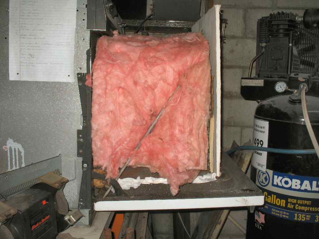
Fig. 15 Extension in Place |
Fig. 16 Extension in Use |
I will be using a set of Downey 3 into 2 headers with my stock intake. I was originally going to have the slightly rusty headers ceramic coated by Jet Hot, but decided it was just not worth the $240 they wanted to do it. I know you are probably thinking, all that work making the engine pretty and you are going to put rusty headers on? Well not exactly. I decided to try a paint by VHT that is supposedly good to 2000 degrees. Yes, PAINT! This is a ceramic based paint that has to be cured in an oven (it CAN be cured on the vehicle using the exhaust heat), in three stages with the final curing done at 600 degrees!
In order to get the headers to fit into my kitchen size, small oven, I had to build an 'extension' to it. This was a hack job pure and simple. I cut up some 16ga material left over from my quarter panel fabrication, and welded up a simple 3 sided cube. It has no bottom, or front, but does have a top with the rear section hinged. See Fig. 14.This will allow me to check on the part.
The way it works is, I coat the piece to be baked, then hang it inside the oven with part of it hanging outside the oven. I carefully slide the extension box into the oven about 6 inches, being careful not to bump the suspended part. The extension rests on the open oven door. See Fig. 15 for the extension in place with the headers inside as a test fit. I stuff small pieces of insulation around the gaps and drape a long piece of pink insulation over the top, and down the sides. Another piece of insulation lays against the back and a piece of drywall holds it in place. Ugly as hell, but it works! See Fig. 16 for the extension in actual use.
I used a drill mounted wire brush to knock off the converted rust, and loosened carbon. Next I went over them with 400 grit to rough them up for better paint adhesion, and finally used compressed air to blow off the dust. Last I donned a pair of Nitrile gloves, and wiped the header down with a rag soaked in Xylene to remove the last traces of dust and any oils. Now they were ready for the primer coat of White VHT.
Fig. 17 Pre-heating Headers |
Fig. 18 Primer Coat |
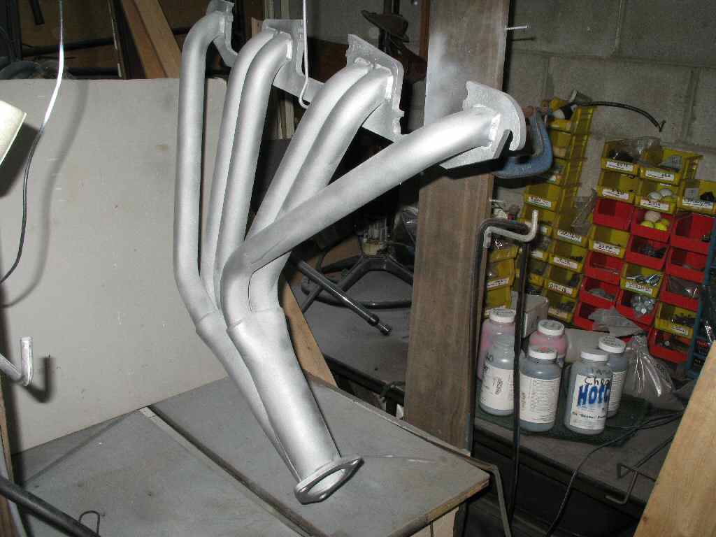
Fig. 19 Top Silver Coat |
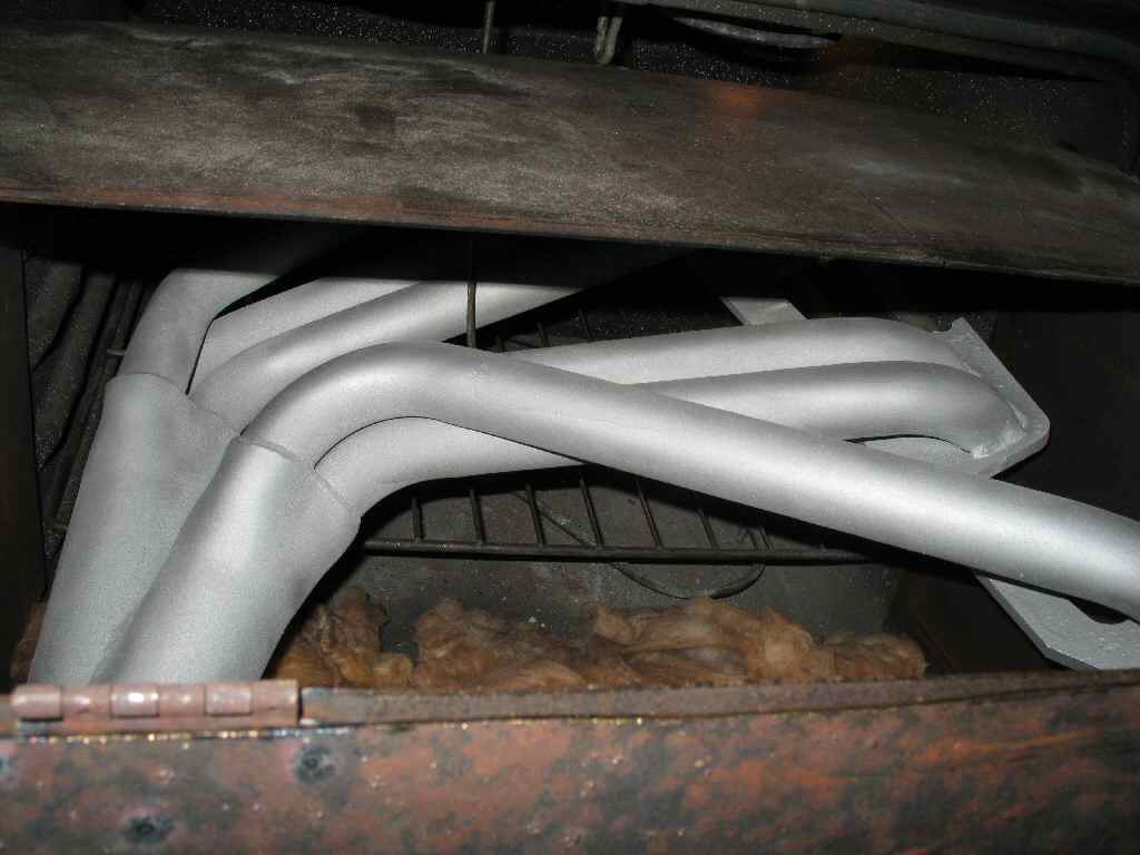
Fig. 20 In Oven Last Time |
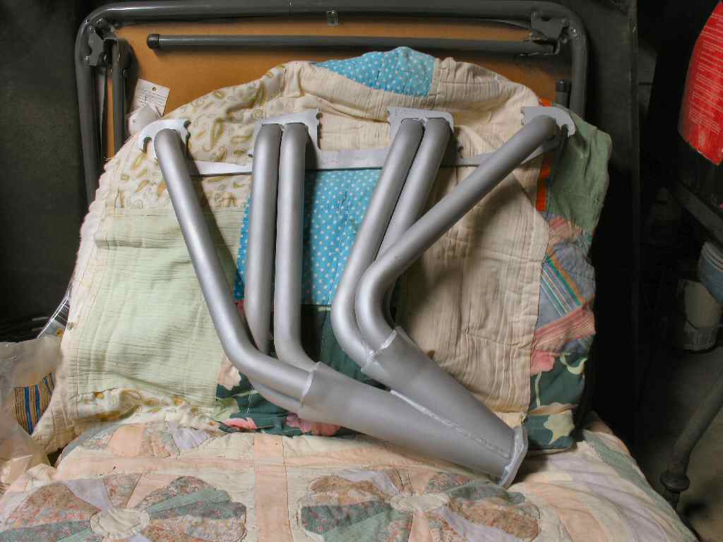
Fig. 21 Final Result |
I hung the headers on my powder coat bench and set a propane heater near them to warm them up. See Fig. 17. I also used a hair dryer blowing into the collector. This kept the header at a constant 80 degrees ensuring good paint bond. I also warmed the spray can. The white primer from VHT sprays really nice. It's thick so doesn't run and covers well with a thin coat. VHT warns not to spray it too thick as it will blister. Fig. 18 shows the header after the primer was applied and let dry for 30 minutes.
Once this paint is dry it can be gently handled. I can tell you, it WILL scratch easily! Putting it in the oven without scratching it was not as easy as I thought it would be. Once it I touched up a couple of areas, insulated the extension and started the curing process.
30 minutes @250 degrees then let cool for 30 minutes
30 minutes @400 degrees then let cool for 30 minutes
30 minutes @600 degrees and let cool for 30 minutes before handling.
Did all that, then hung them up again to spray the top silver coat. I was not real impressed with the silver paint. It was much runnier than the white primer, and I had many runs that had to be cleaned up with the Xylene. You can see the mottled, and splotchy appearance that resulted in Fig. 19. It might not pass a concourse inspection, but it works for me. After letting them dry for 30 minutes it was back in the oven, (see Fig. 20), and repeat the cure process.
The final result? I liked the final finish. It's a slightly textured top coat that appears to be over a shinier , silver color. I was told it might be possible to dry sand the primer and top coat to get a MUCH smoother, shinier finish on the headers.
Fig. 22 New 2F Studs |
Fig. 23 Misaligned Gasket |
Fig. 24 Bit too Big |
Fig. 25 Fitted with 12mm Studs |
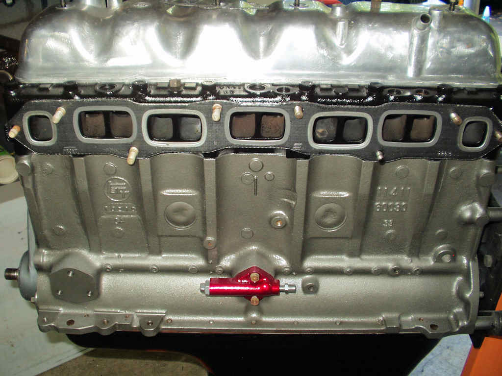
Fig. 26 Intake Installed |
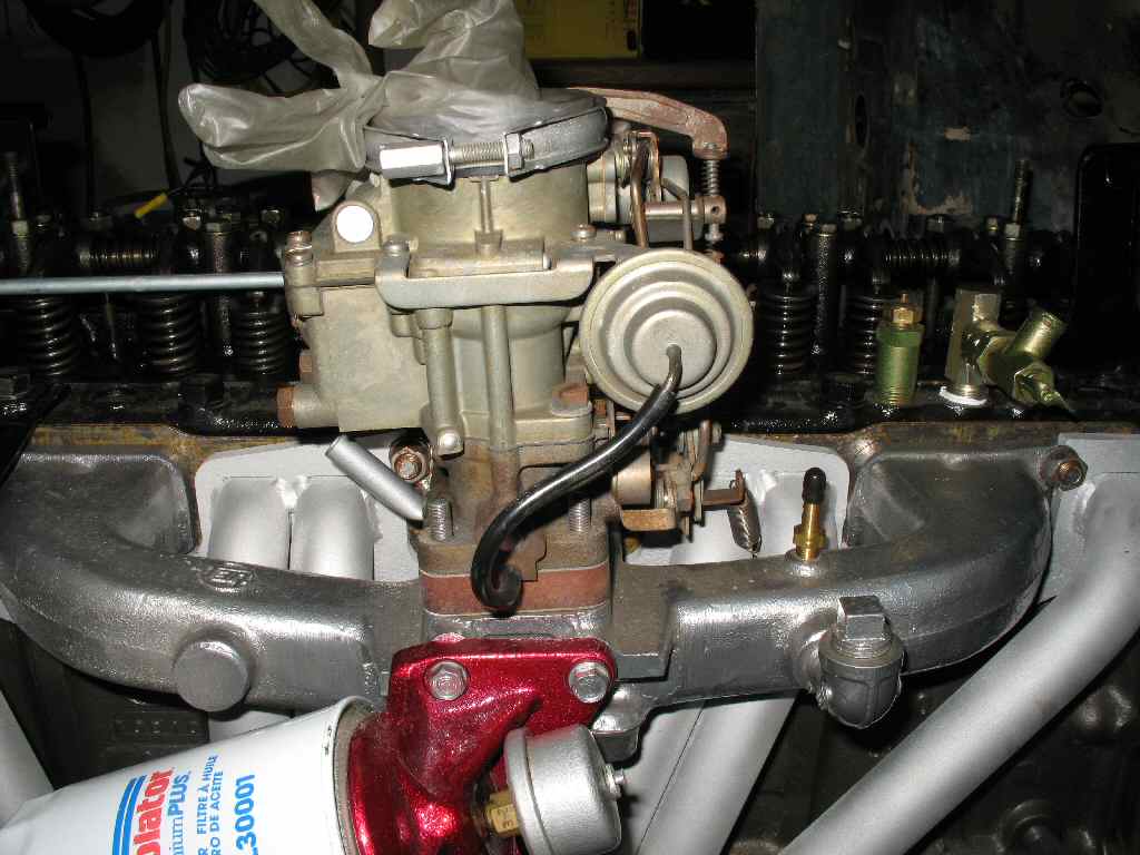
Fig. 27 Carb Installed |
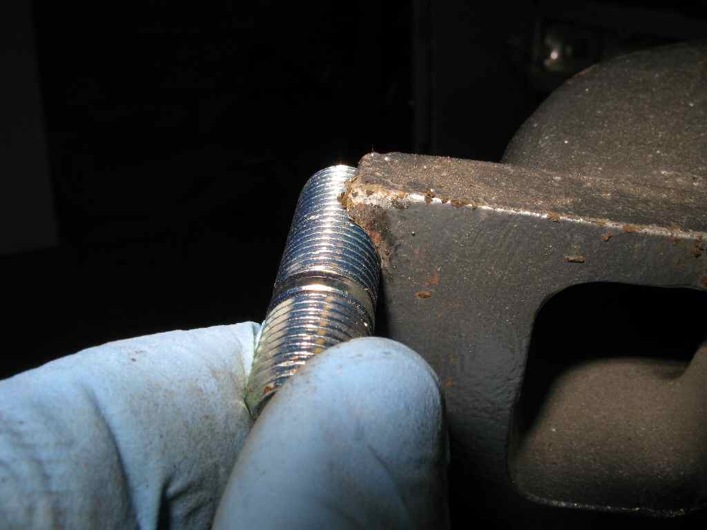
First, I replaced the old studs with a set of 2F studs I ordered from CDan. The 2F studs are 12mm on both ends, whereas the F studs are stepped studs: 12mm into the head, but 10mm for attaching the intake/exhaust. Also the two end studs on the F head are only tapped to 10mm. I used two of the older stepped studs on the ends, but reversed them so the 10mm part threaded into the head, and the 12mm part stuck out to attach the intake/exhaust. Worked out great! See Fig. 22.
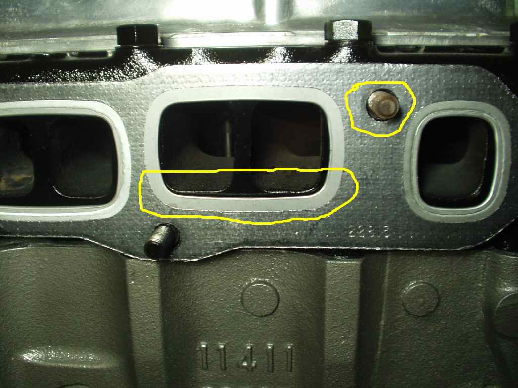
I slide the new Fel-Pro gasket over the studs, and noticed something interesting: The gasket aligns better with the head ports when using the bigger studs! In Fig. 23 you can see how the gasket is not aligned properly with the ports using the old studs, and how there is lots of space around the 10mm studs. So next I attempted to set the headers in place. Hmmmm..., wouldn't fit? I tried several times, working them back and forth, but they would not fit over the studs. It was like they had shrunk! I suddenly had this horrible thought; the headers had warped from being baked at high temps for a couple of hours! Having visions of a torch, and my hydraulic press on my newly coated headers was a bit depressing... but... as usual it was something I had done. The 12mm 2F studs are, guess what? 2mm BIGGER... See Fig. 24. After a bit of filing, I got the header to fit. See Fig. 25.
Since the headers needed grinding, it was logical to assume the intake would need the same treatement. It did. A few passes with a large round file, and all was good. I sat the intake in place, and starting in the middle of the intake, I slowly torqued the nuts down. I first went to 20 lb ft, then 40, and finished with 50 lb ft. I did NOT use any sealant on the gasket. I will of course tighten them again after the first running of the engine. See Fig. 26.
Now I could bolt on the oil filter and carb. See Fig. 26. I will need to connect the choke cable so I can control the choke upon start up.
Fig. 27 Before |
Fig. 28 After Polishing |
Fig. 29 Powder Coated |
Man it's been a long road getting to this point! I had to finish up a few things to actually start the engine. One was the Valve cover. I had bought the valve cover off E-Bay. It apparently had sat outside, and was covered with a nice coat of algae. See Fig. 27 . I spent some time cleaning it up and polishing the aluminum until it shone. See Fig. 28. My intention was to powder coat it anodized red like several other parts on the Cruiser. I sat it aside for a long time while I did other things to the engine.
The time had finally come to decide what to do with the valve cover, so I took a poll on IHMUD, and overwhelmingly they voted to leave it polished. Hmmm... like any good husband, I asked the wife what she thought. She looked over the engine compartment and said, " Red anodized: If you are going to go pimp, may as well make it complete! " Ok... red it is. \
I prepped the cover prior to coating by wiping it down with Xylene, placed
it in the oven for one hour at 550 degrees to let it outgas, let it cool, then
wiped it down again. Normally, to use the red anodized, I first coat the piece
with Xtreme Chrome (to give the underlying shiny look), and while it is still
hot, apply the red. Since the cover had already been polished, I decided to
coat the valve cover cold. Big mistake...
To start, the red powder would not stick to the polished surface. Since I had
never used the red alone I figured there was something wrong with my coating
setup. I made several adjustments to the gun, and finally got, what I thought,
was a good coat of powder on the cover. Into the oven at 450 degrees, let it
flow out, then 20 minutes @400 degrees. I ate lunch while it cooled. When I
brought it out of the oven, I was really disappointed. There were several places
where the coating was not thick enough and the aluminum was showing through.
I decided I would re-heat the valve cover to about 350 degrees, spray on another coat of red and let it finish curing at 400 degrees. So... back into the oven, heat it up, spray on a THICK coat of red, which partially melted so stuck really well and back into the oven to cure for another 20 minutes. I was confident in the outcome...
That's when the disaster hit.... We lost power to the whole house....
It was out for over an hour, which allowed the valve cover to cool to the point
the partially melted powder solidified. It had a wrinkled texture. I thought
I could just re-heat the part and cause it to flow out, but that did not work.
The pic shows how it turned out. The wife actually likes the 'textured' surface, but it does not match the other pieces. I got on the web and ordered some powder stripper from Eastwood Co. If the cover grows on me, I'll leave it be. Otherwise I will strip it and re-do it. This time I'll give it a coat of extreme chrome then apply the red while it's hot. Live and learn. See Fig. 29 for the 'after' pic.
Hosted by Global Software, Inc.
©1998 - 2023 Mark C. Baker Web Designer
Please: No part of this web site may be used without express permission... email mbaker@globalsoftware-inc.com for permission.
