The clutch installation starts by inspecting your existing
parts. This OEM Toyota clutch has only about 10K on it and everything was
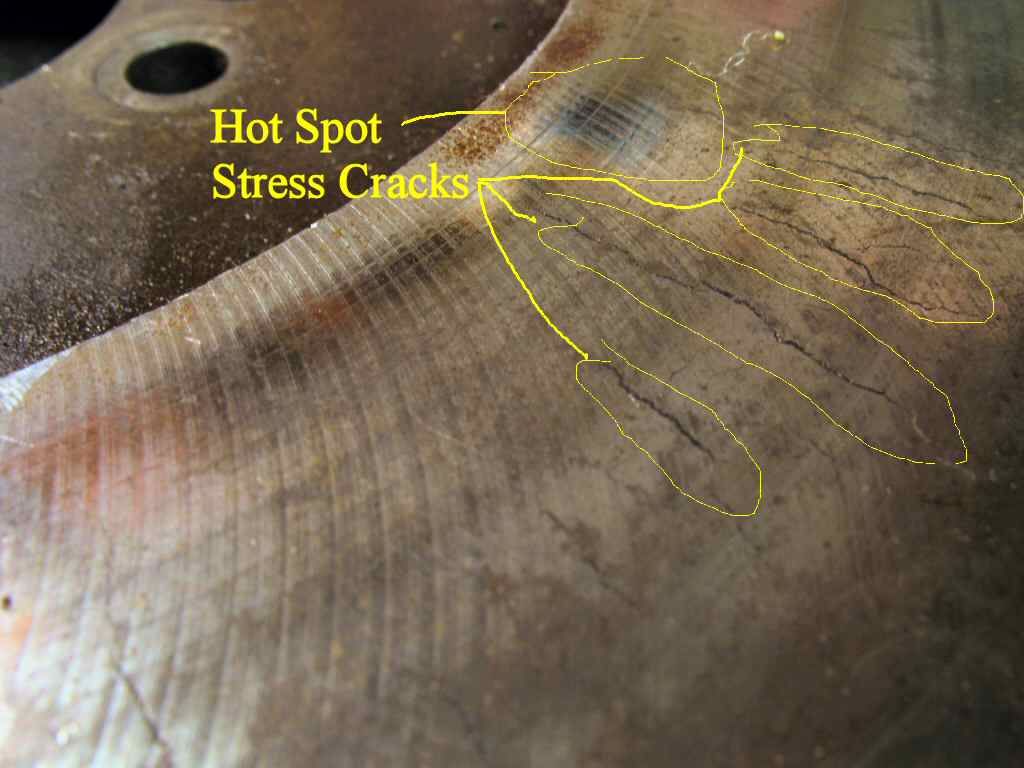
in excellent shape. (Just for reference I had a flywheel that a club member
gave me that needed to be resurfaced badly. Just so you know what that looks
like look at Fig. 0.
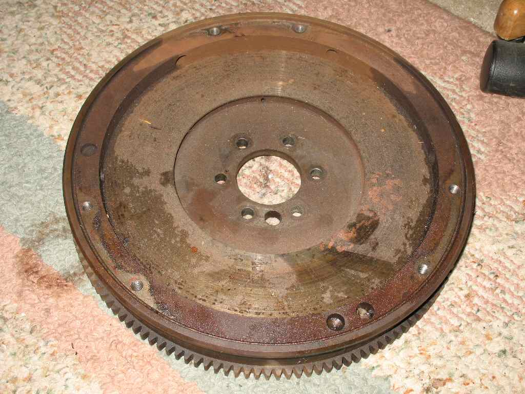
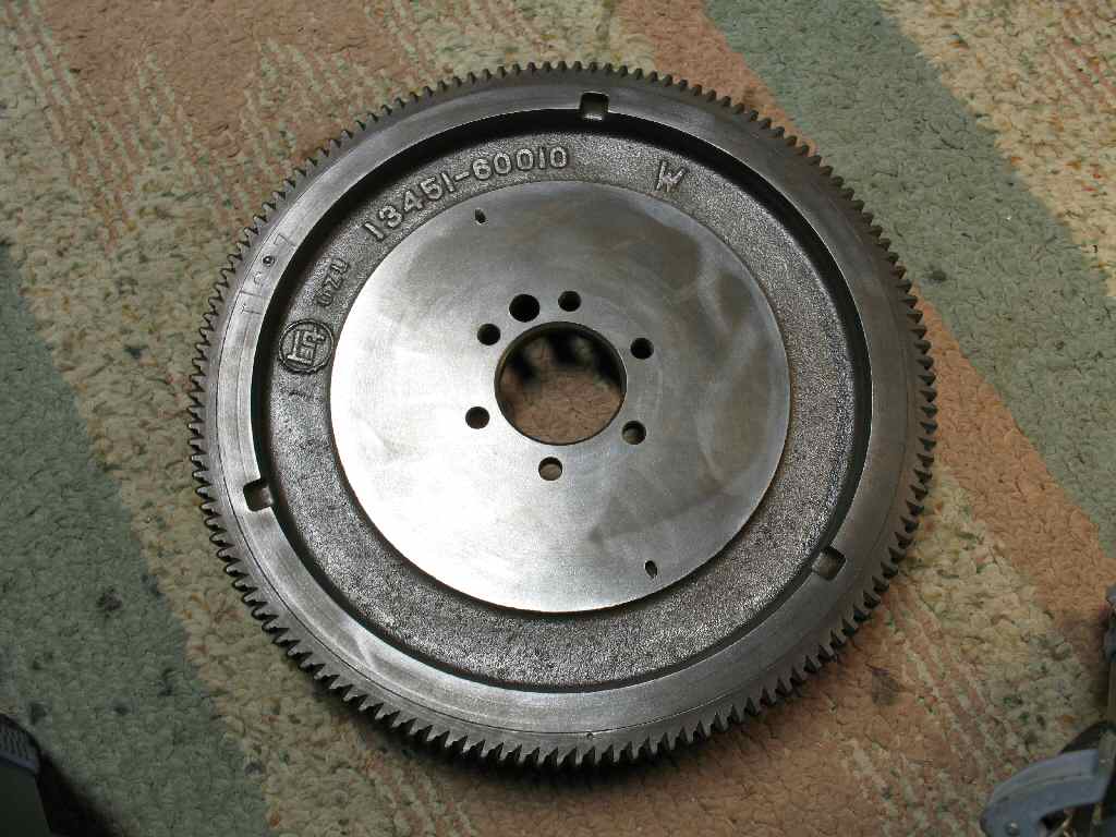
The flywheel had been out for about a year and had some
surface rust here and there so I dropped it into the de-rust tank for 24
hours. A quick going over with a wire brush on a drill gave me a new flywheel!
See Fig. 1-2.
Find the 6 10mm x 1.25 x 30mm crank bolts and the locking
plates. You will also need some red Loctite You don't want these coming loose!
Clean the bolt threads and apply a couple drops of red loctite to them. Lift
the flywheel into position (37 lbs be careful!) and use the dowel pin the
align it in position. It will sit there by itself as long as you don't bump
it. Place the lock plates under the bolts and hand tighten them. See Fig.
3.
Now grab your torque wrench and something to jam into the
ring gear teeth. I used a honking big screwdriver. Have someone hold the ring
gear in place while you torque the flywheel bolts in a crisscross pattern.
Start with 20 ft lbs, go to 40 then finally 58 ft lbs. Bend the corners of
the lock plates up against the flat side of the bolts with a screwdriver and
hammer to lock them in place.
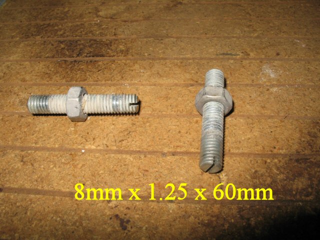
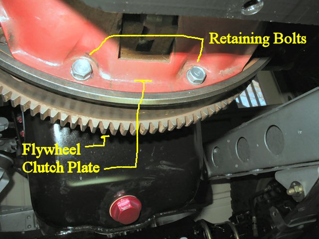
Rotate the flywheel to put one of the clutch plate retaining
bolt holes at the bottom. Thread a 8mm x 1.25 x 50-60 mm stud or a bolt
with the head cut off finger tight into this hole. This will hold the
pressure plate while you start the bolts. See Fig. 3A.
Using brake cleaner, or any other non-residue leaving cleaner,
clean the surface of the flywheel where the clutch disk sets. Do the same
for the pressure plate.
Gather the 6 8mm x 1.25.x 18mm class 4 clutch cover plate
bolts, your alignment tool, (I removed and used the front output shaft
from my 3 speed tranny :-) ) the clutch disk and the clutch cover (pressure
plate). You will also want some blue loctite.
Fig. 4
Backwards!!!
Fig. 5
Correct!
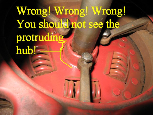
Lift the clutch disk in place and STOP!!!!!!!!
You did check to make sure the clutch disk
is turned correctly? Trust me... After reading about this and seeing pics
and hearing all the stories, I STILL put the damn thing in backwards! Good
thing I caught it before putting the tranny in! See Fig.4 for
a backwards disk and Fig. 5 for a correctly
oriented disk. Remember protruding HUB FACES ENGINE!!!!!!!! You might even
consider putting a large piece of tape labeled REMOVE ME on the side that
faces the pressure plate so you will know which side goes where.
OK, back to installing. Place the clutch disk into the bell
housing and let the bottom edge rest in the inner flywheel. The top edge
will fall back toward you. Lift the pressure plate up into the bell housing
until you can get it over the stud you put in earlier. (Sorry no pics of
this.) Once it's secure on the stud insert your alignment tool through
the clutch disk into the pilot bearing. This will center the disk and allow
the tranny input shaft to easily go in later.
Now, one by one, rotating the flywheel around for access,
install the 6 clutch cover bolts. Put a drop of blue loctite on each one
and only tighten them finger tight! Remove the stud of course!
Fig. 6
Securing Clutch Plate
Fig. 7
Measuring Setup
Fig. 8
Adjusting Fingers
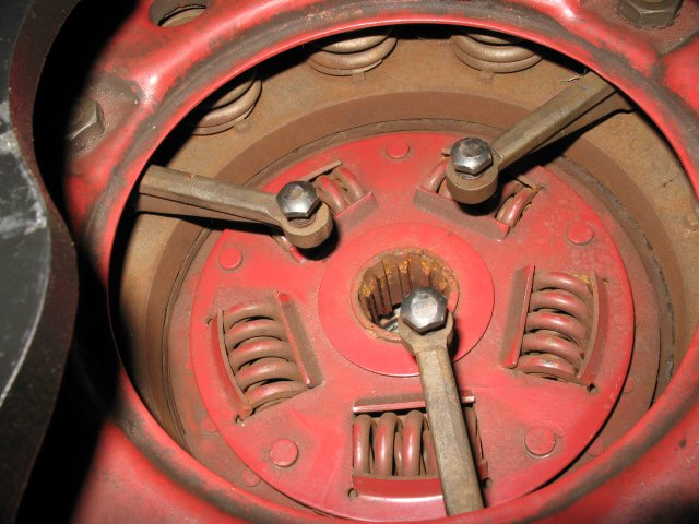
Refer to Fig. 6. Now
according to the FSM, you should tighten the 6 bolts, one turn at a time
crisscrossing round and round to slowly compress the pressure plate springs.
I did more like three turns... It takes a little while... and wears your
arms out turning the flywheel. Oh yeah, don't forget to remove the spark
plugs so the engine turns easier!
Once done carefully torque them to 11
ft lbs. They are small bolts, don't break
them
off!!!
Now we need to check the fingers of the pressure plate to
ensure they are the correct distance from the tranny mounting surface.
The point is to get them all the SAME distance so the T/O bearing engages
the fingers evenly allowing the disk to engage/disengage without chattering.
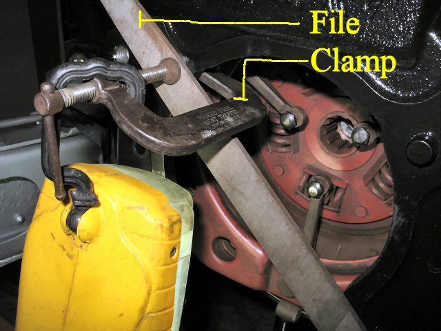
Find a stiff, know good, straight edge and clamp it to the
the bell housing as shown in Fig. 7. I used
a file. Measure the thickness of the straight edge and write it down.
My file was .170 thick.
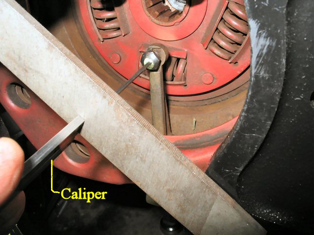
The FSM says each finger tip should be 2.930" from the tranny
mounting surface. so add your measurement to the 2.930 for the total. Mine
was 3.087. I set the dept gauge on a set of calipers to that amount and
used it to measure each finger. Refer to Fig. 8. I had one that was way
off! (Thanks to my PO who is also my brother...) I adjusted that one to
match
the other
two and used red loctite on the threads to lock it down.
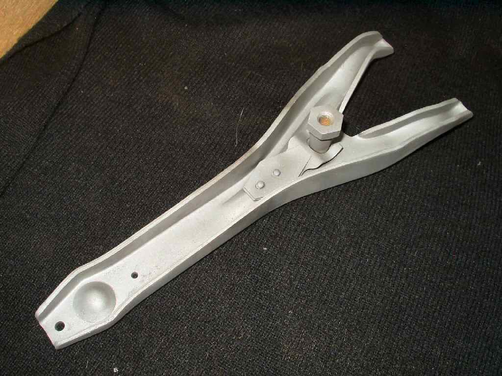
Fig. 9
3 speed Release Fork
Fig. 10
T/O Pivot Greased
Fig. 11
Release Fork Ball Greased
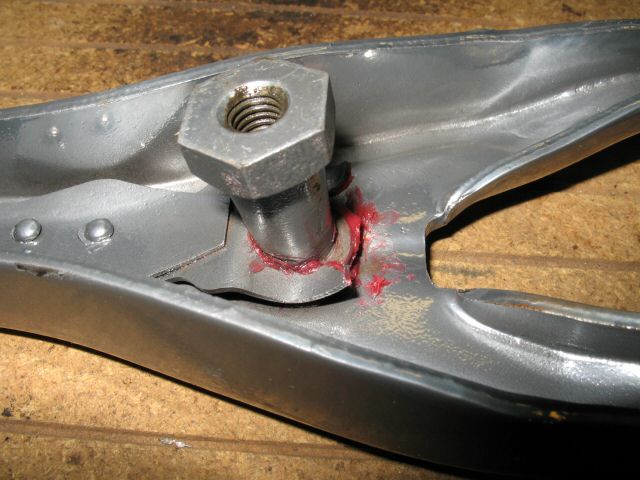
Fig. 12
Arm Bolt
OK! We got the clutch in! Now lets get the release arm and
T/O bearing in. Fig. 9 shows a 3 speed arm.
As shown in Fig. 10-11 grease those points on the bearing
and arm. I used red boat trailer grease. It's water proof.
Insert the arm up through the lower bell housing and out
the side your slave cylinder is on. Put a drop of blue loctite on the fork
ball bolt ( 8mm x 1.25 x 25mm), and insert it through the bell housing,
and into the fork ball
pivot.
Using
a
17mm
wrench
to hold
the fork ball, and a 12mm for the bolt, tighten it until it's snug. See
Fig. 12.
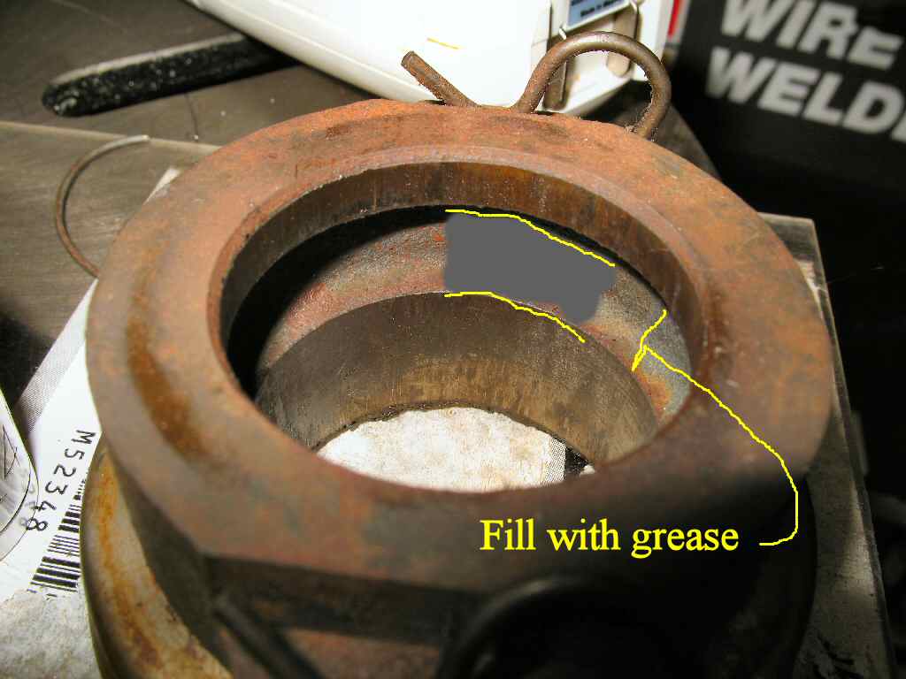
Fig. 13
Greasing T/O Hub
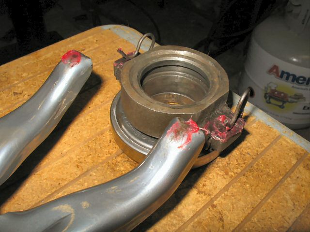
Fig. 14
T/O Mounted
Fig. 15
CCOT Master/Slave
Refer to Fig. 13 and fill
the groove in the body of the T/O bearing
mount with grease. Apply
a thin film of grease to the T/O inner hub then the bearing surface that
contacts the fingers. Finally a bit
on
the
finger tips that contact the T/O bearing.
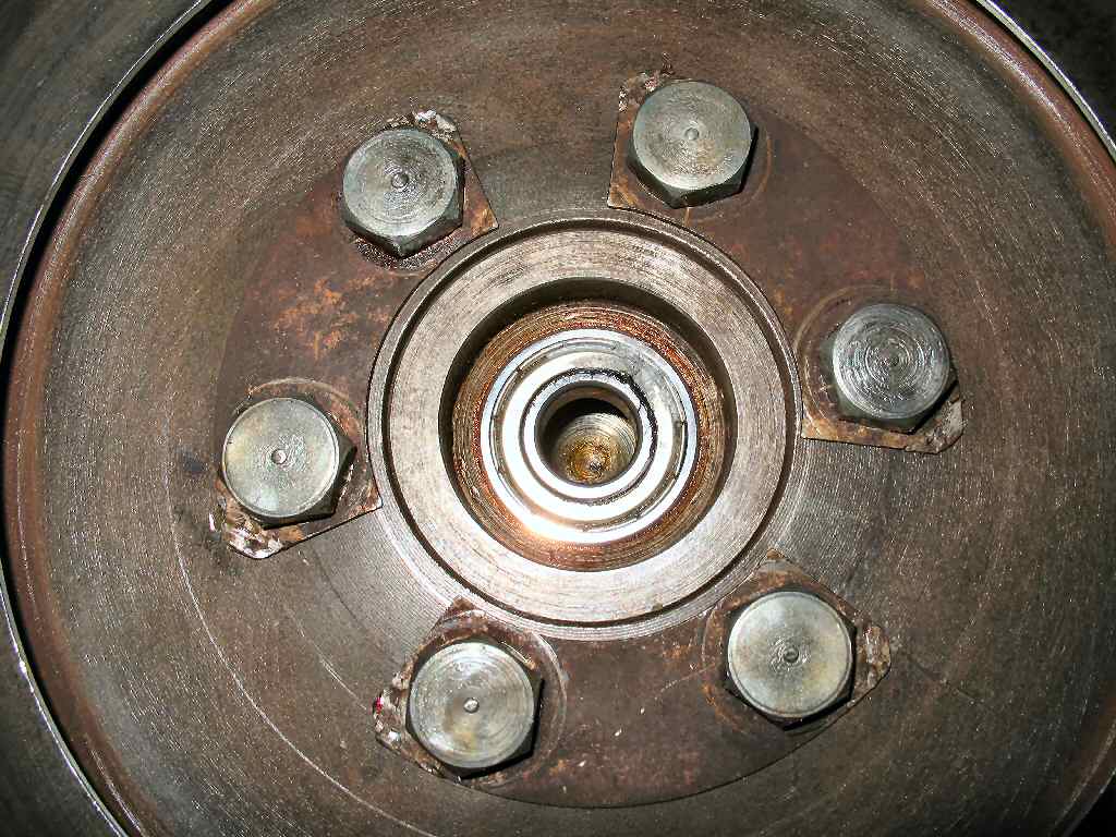
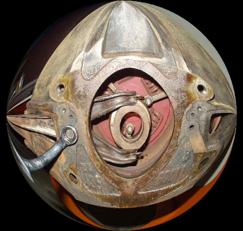
Slide the T/O bearing onto the release fork as shown in
Fig. 14. I forgot to take a pic of the release fork and T/O bearing
part of the install but here is a pic of the old one before I removed
it so
you
can
see how
the
T/O
bearing clips
on to the end of the fork release arm.
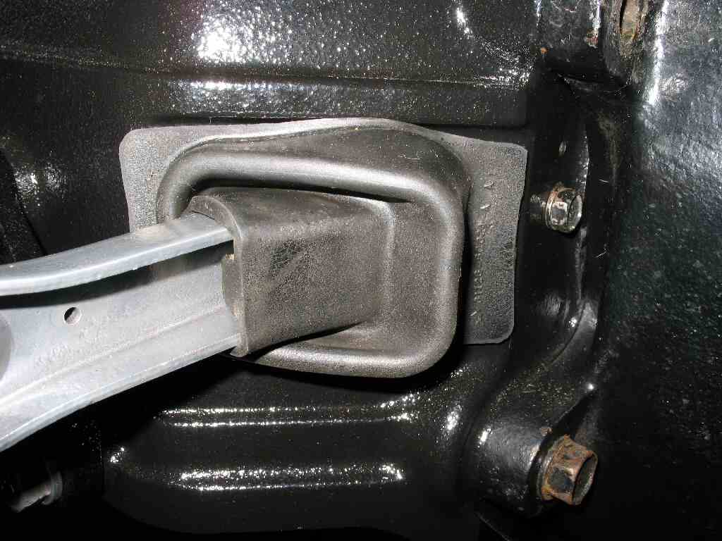
You can now try to put the rubber boot on the arm. Good
luck, it's a pain in the ass to get it on but needs to be there to keep
as much crap out of the clutch area as possible. See Fig.
12.
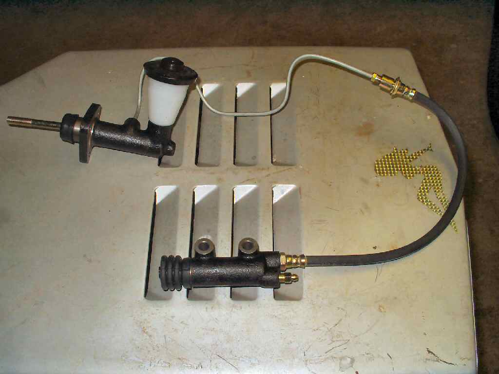
Next I put the slave cylinder from CCOT on. This is actually
a 74> slave cylinder they include with their master cylinder upgrade kit
for the early Cruisers. See Fig. 15.
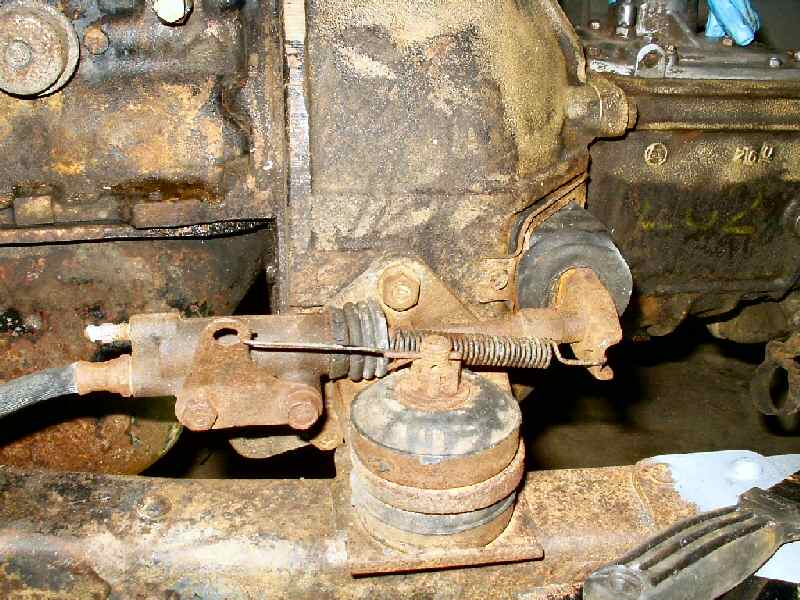
Fig. 16
Before
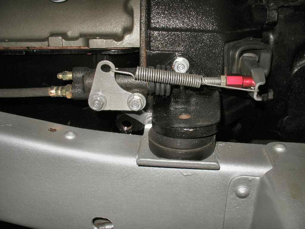
Fig. 17
After
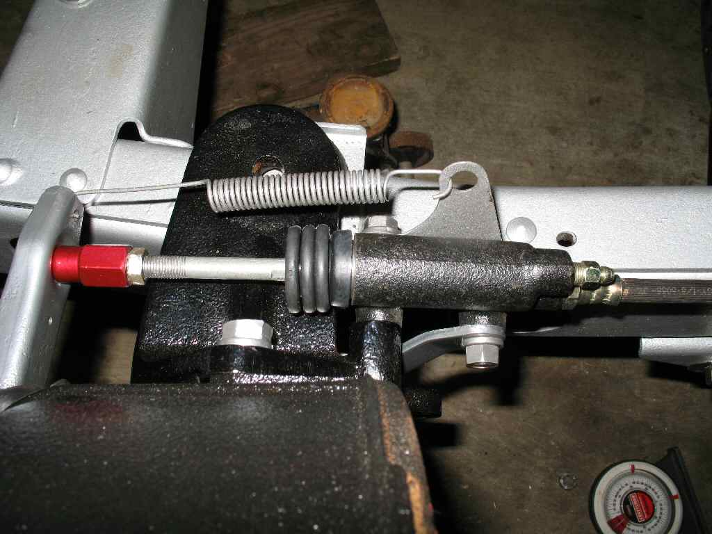
Fig. 18
Top View
I had powder coated the mounting brackets and things, so
it was a matter of just bolting it up. Have to wait till the body is on
to bleed it!