OK, we left off with misty eyes from the incredible
beauty of a fully cleaned and extreme chrome powder coated 3 sp case....
Sorry, hold on a sec, got to wipe my eyes...
:-)
Just to keep confusion down when I refer to
the 'front' of the t-case I mean the side that faces the tranny.
Get all your parts together, have a clean
work bench, get plenty to drink and lets get started.
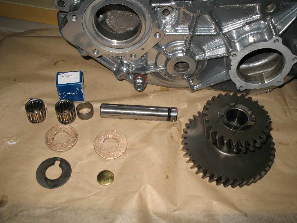
Get the idler gear and shaft, new thrust washers and the
shim(s) you set aside from the teardown, retaining bolt and keeper, two
needle bearings, spacer, and the new 'freeze plug'. You will also need
a feeler gauge set. See Fig. 1.
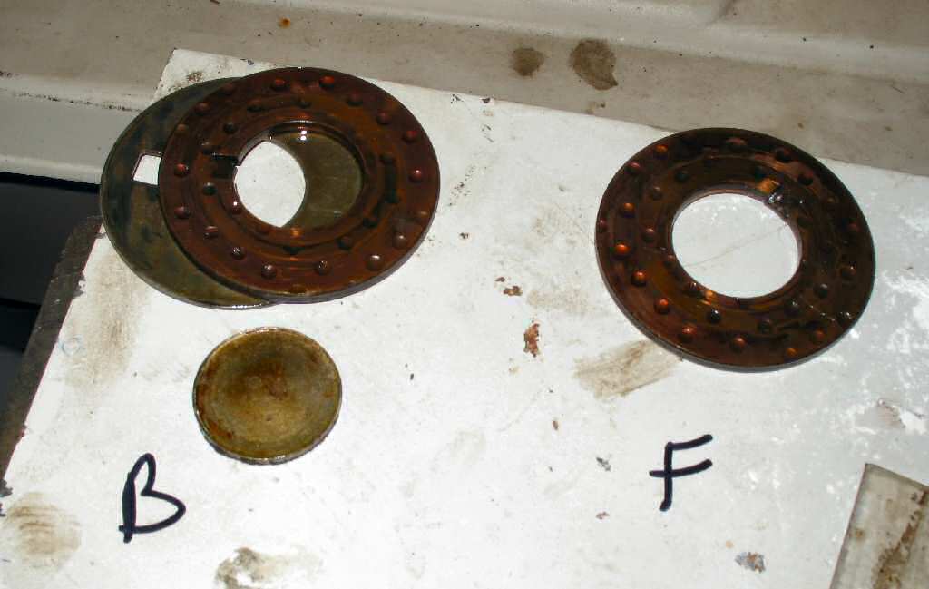
When I disassemble the case I took a pic of the washers
and shim placement. See Fig 2. I even labeled
B for back of case and F for front on case. (Even though I labeled it I
ended up putting the shim on the wrong side! However it will not affect
anything. The following steps are the CORRECT placement!)
Wash the the idler shaft and idler gear in soap and water,
and rinse well. Blow them dry then install a new O-ring
on the idler shaft from the rebuild kit. Give it
a coat
of
90W
and
slide it
into the rear
of the case just far enough to hold the spacer shim and the thrust washer
on it. The shim goes against
the case! Make sure the thrust washer 'tab' is in the groove. Some thick
grease will
help
hold
it in place.
Dip the two idler gear needle bearings into some 90 weight.
Slip one bearing into the idler gear from either side, then the idler gear
spacer then the other bearing. Support it so the bearings don't slide out
and put it within easy reach for the next step.
Stick your finger through the idler gear hole in the front
and hang the thrust washer from it. Now using your other hand pick up
the idler gear and place it into the case with the small gear toward the
rear of the case.
Slide the idler gear shaft through the gear cluster, through the thrust
washer and into the front of the case. Temporarily install the keeper and
retaining bolt.
Get your feeler gauge set and refer to the FSM to measure
the thrust clearance. Mine measured .015" , in spec for the shim I removed.
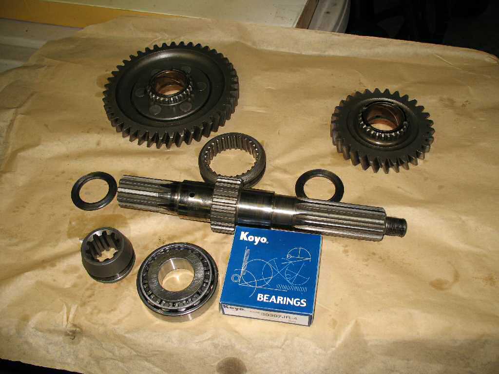
Now lets start assembling the main output shaft.
Fig. 3
Main Output Shaft Parts
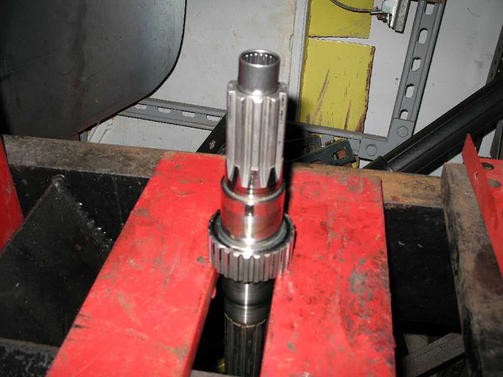
Fig. 4
Installing Needle Bearing
Fig. 5
Installing High Speed Gear and Bearing
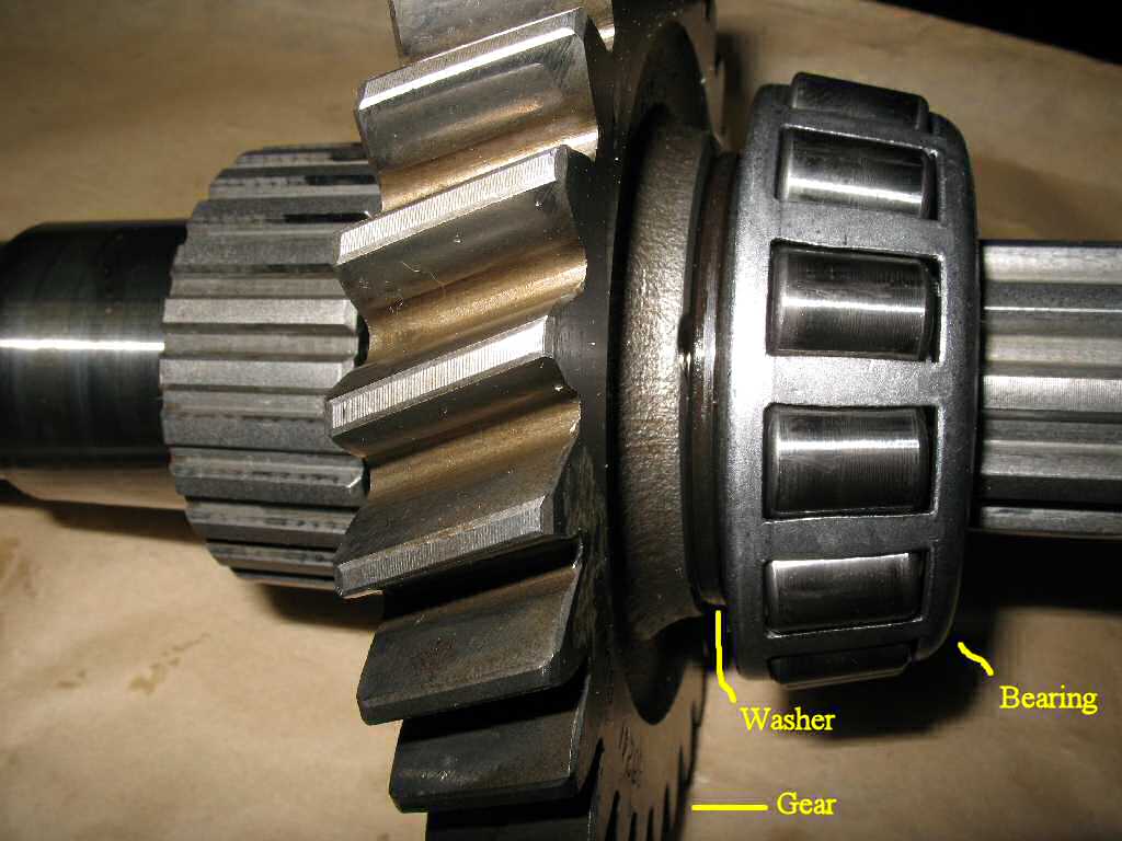
Fig. 6
Order of Parts
Gather all the parts shown in Fig.
3. Wash the parts in
hot soapy water, rinse and blow dry.
Place the output shaft as shown in Fig.
4. You can use 2
x 4's or what ever but make sure it is a SOLID support! coat the inside
of the shaft and the outside of the bearing with 90W then carefully drive
the bearing into the shaft until the end of the bearing is flush with the
shaft end. I used a plastic faced hammer but a small board across it will
work just as well.
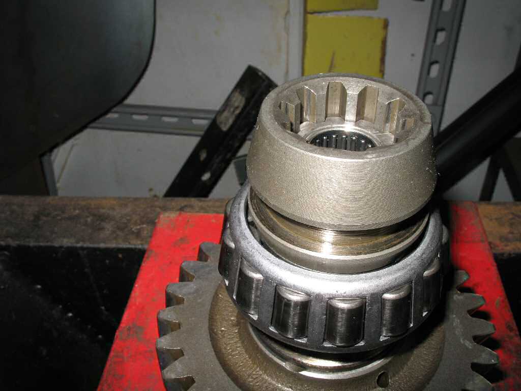
Leave the shaft there and place the high speed gear (small
gear) and thick washer over the shaft followed by the Koyo 30307JR-4 bearing.
Note the bearing orientation and don't put it on upside down! I used the
front drive clutch sleeve to drive it on since it's a perfect fit!
See
Fig. 5. Fig. 6 shows
the correct order the parts should be in.
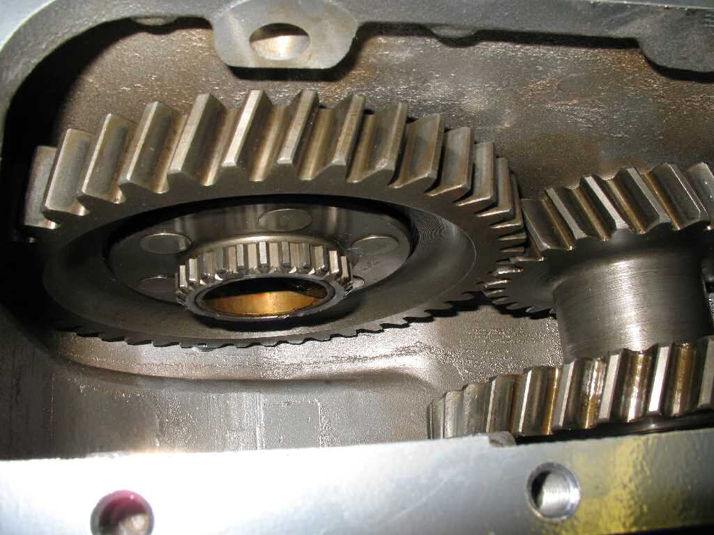
Fig. 7
Low Speed Gear Installation
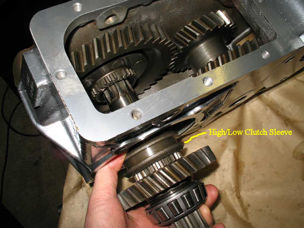
Fig. 8
Output shaft Assembly Installation
Fig. 9
Bearing Installation
Fig. 10
Supporting the Low Speed Gear
Fig. 11
Bearing SST
Fig. 12
Bearing Race Installation
Place the large low speed output gear into the case as shown
in Fig. 7.
Place the Hi/Lo Clutch Sleeve onto the output shaft and
slide the whole assemble into the T-case as shown in Fig.
8. The shaft will pass through the large low speed gear and exit
the other side. Slide it all the way in until the small High speed gear
engages the idler gear.
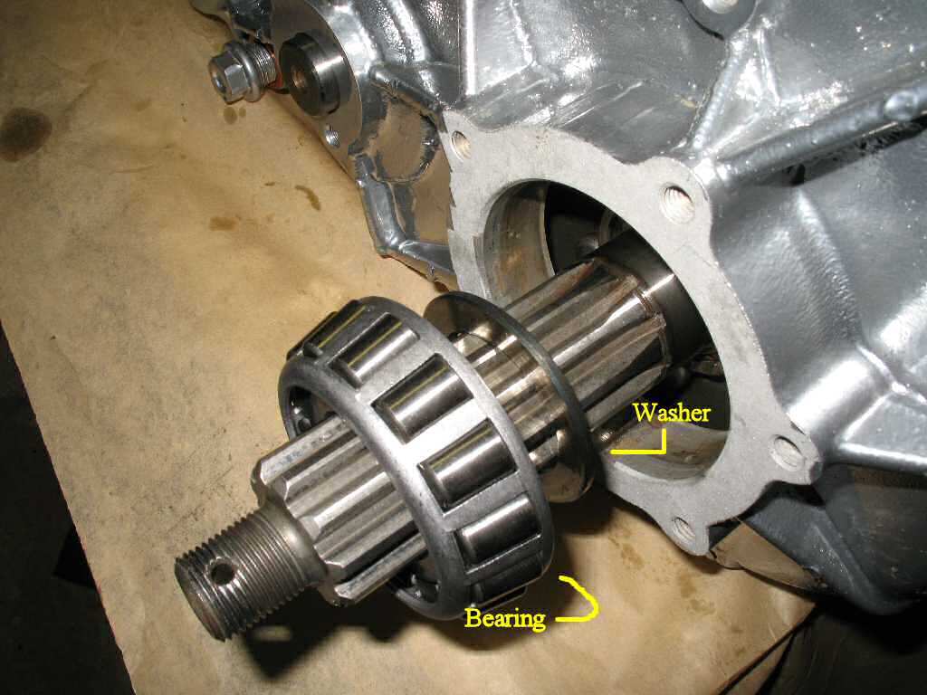
Place the large washer and the other Koyo 30307JR-4 bearing
onto the shaft as shown in Fig. 9.
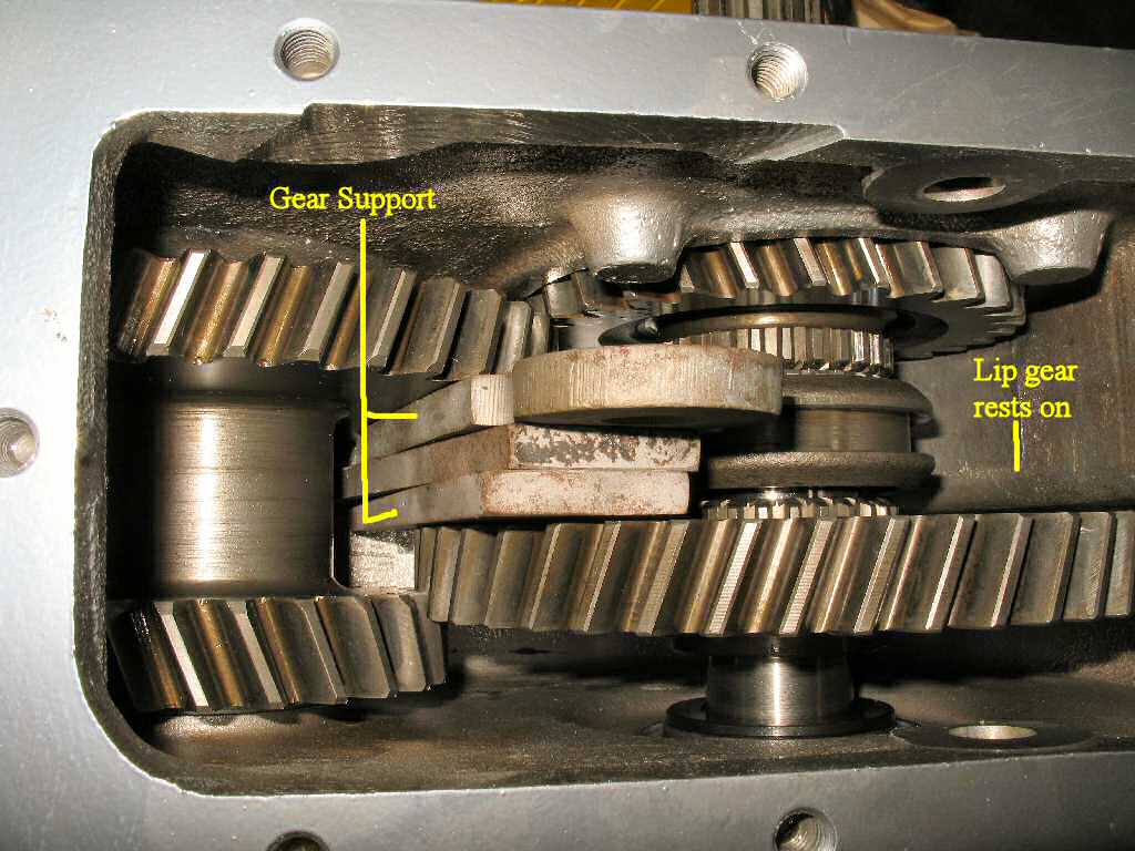
Referring to Fig. 10, place
some steel plate or some other type of spacer to support the large high
speed
gear so you can drive the bearing on without breaking the gear. The other
side of the gear will rest on the inside of the T-Case. I used some old
shackle side plates.
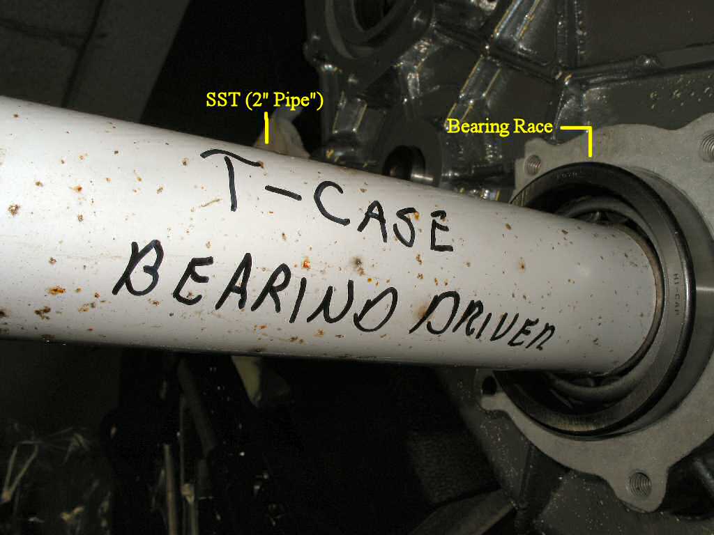
Now you need to make a SST. Cut a section of 2" diameter
pipe about 7" long. Exhaust pipe works great. Use it to drive the bearing
all the way on the shaft.
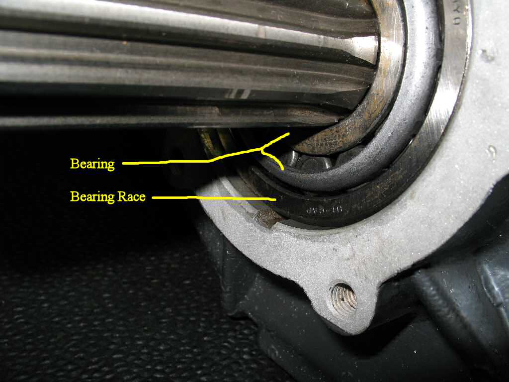
Place the bearing race over the shaft and drive it until
it's flush with the case. When you install the speedo housing it will set
this race to the proper depth. I was able to just install it by hand! See
Fig. 11-12.