From IH8Mud
.jpg)
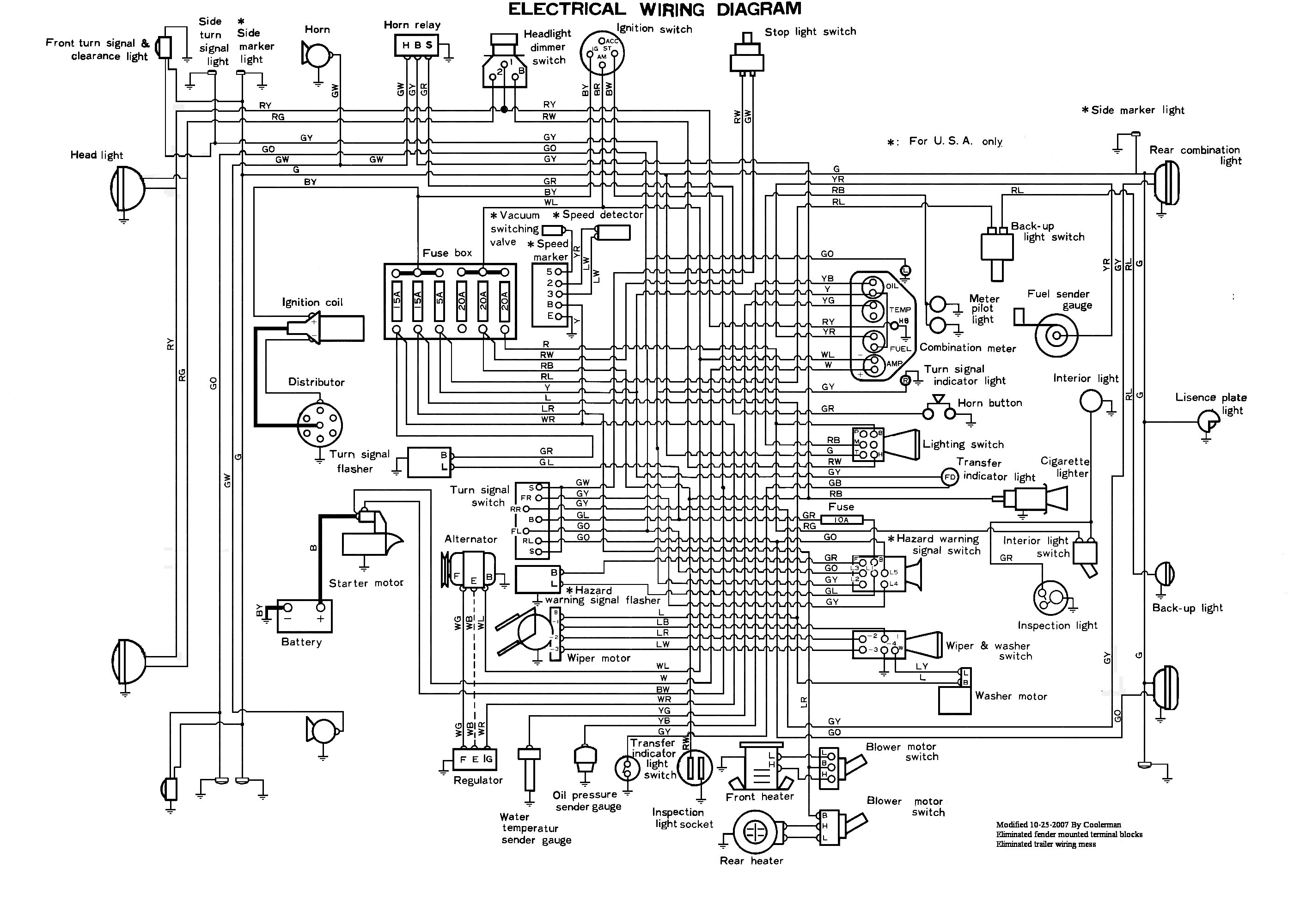
From Factory Manual
Someone on the CCOT bullentin board asked for help with identifying the wiring under the hood of his 1972 Cruiser. I pointed him to the wiring diagram that I had gotten from IH8Mud.com . This diagram was pretty rough when I first looked at it. I loaded it into Paint Shop Pro and 'fixed' it. This involved several hours of work on my part cleaning it up and re-labeling it. Here is the result:
From IH8Mud |
From Factory Manual |
Fig. 1
Various Early Wiring Diagrams I have Found
His wiring had been badly hacked up and he didn't know what connectors went to what. I took a bunch of photographs and supplied him with a list of all the connectors under the hood and their purpose. Here is that information for everyone to have and share.
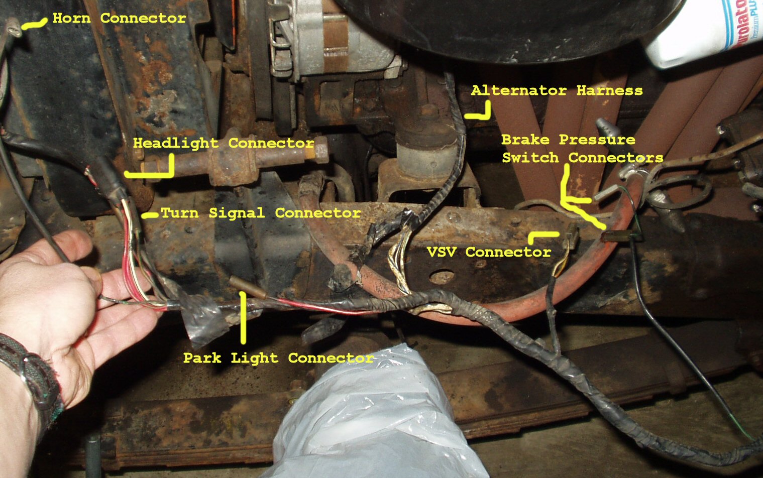
Fig. 2
Drivers Side Harness
Single Female spade connector (See Fig. 2)
Terminal Description |
Wire Color |
Function |
To |
| Female Spade | Green/White | +12V for Horn
|
Horn Relay on passenger fender through harness |
Table 1
3 Pin triangle shaped plug.(See Fig. 3 )
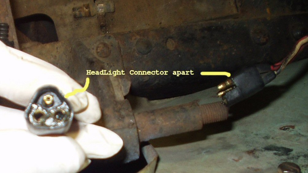
Fig. 3
Terminal |
Color |
Function |
Destination |
| Male pin |
White/Black |
Ground |
Ground |
Left Female Pin |
Red/Yellow |
High Beam |
Dimmer Switch |
Right Female Pin |
Red/Green |
Low Beam |
Dimmer Switch |
Table 2
Two female bullet connectors (See Fig. 2)
Terminal |
Color |
Function |
Destination |
| Female Bullet 1 | Green/Orange | Turn Signal Bulb | |
| Female Bullet 2 | Red/White | Park light bulb |
Table 3
1 female bullet connector(See Fig. 2)
Terminal |
Color |
Function |
Destination |
| Female Bullet 1 | Red/White | Park Lamp |
Alternator wiring connector(See Fig. 4-4A)

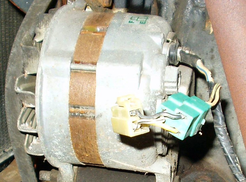
Fig. 4-4A Alternator Wiring (Note the ADAPTER!!!) You OEM will probably NOT have this adapter!!!
Terminal |
Color |
Regulator connection |
E Terminal |
White/Black |
Goes to Regulator E terminal (One on
left by itself) |
F Terminal |
White/Green |
Goes to Regulator F terminal (Bottom
one on right) |
| N Terminal | No connection | |
| Bat terminal | White/Blue | Large 8 ga wire goes to amp gauge then
to battery, fuse box, and ignition switch |
Table 4 (OEM Wiring)
The adaptor thing shown in Fig. 4and 4A is wired as follows
From Harness |
Green plug |
Connecting Wire |
White Plug to Alternator | Alternator |
White/Black |
Left terminal |
Black |
Top terminal | F terminal |
White/Green |
Top terminal |
White/Black |
Left terminal | E terminal |
No Connection |
Right terminal |
Yellow |
Right terminal | N |
Table 5 (Adapter Wiring)
2 pin female plug (See Fig. 2)
Terminal |
Color |
Function |
Destination |
| Top connector | White/Black | Ground | Ground |
| Bottom Connector | Yellow/Red | +12V from computer | To Emission Computer |
Table 6
Two Slide on Connectors in Series(See Fig. 2)
Terminal |
Color |
Function |
Destination |
| Slide on connectors | White/Green | Brake Pressure Switch | Brake Test Switch |
Table 7
3 screw terminals
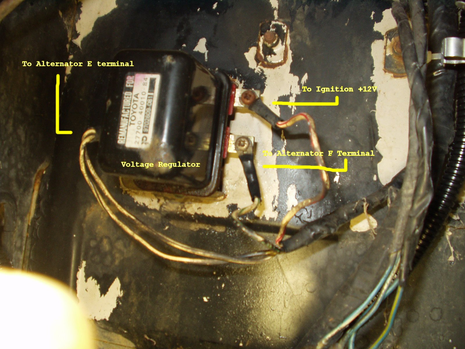
Fig. 5
Terminal |
Color |
Function |
Destination |
| Left terminal | Two White/Black wires | Ground | One to alternator E Terminal |
| Right Bottom Terminal | White/Green | Alternator F terminal |
|
| Top Bottom Terminal | White/Red | +12V | Switched Ignition Fuse |
Table 8
3 screw terminals
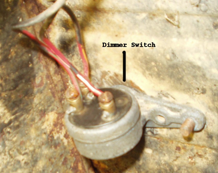
Fig. 6
Terminal |
Color |
Function |
Destination |
| B: Bottom terminal | Red/White | +12V | Headlight Switch terminal H |
| 1:Top Left terminal | Red/Green | Low Beam | Headlight Low Beam |
| 2: Top Right terminal | Red/Yellow | High Beam | headlight High beam and to high beam indicator in dash |
Table 9
Two Female Spade Connectors

Fig. 7
Terminal |
Color |
Function |
Destination |
Spade 1 L terminal on stock motor |
Blue/Yellow | Washer Motor Ground | Ground |
Spade 2 B terminal on stock motor |
Blue | + 12 | 20 Amp Fuse in Box |
Table 10
Two Bullet Connectors
Blue/White = Unknown Located on firewall
Blue/White = Unknown Located on firewall
2 Female Bullet Connectors(See Fig. 7)
Terminal |
Color |
Function |
Destination |
| Bullet 1 | Red/Blue | To SPST Switch | To backup light |
| Bullet 2 | Red/Blue | To SPST Switch | To 5A fuse in fuse box |
Table 11
If you have the 3 speed with the floor shift kit you can make a jumper wire
to connect these wires to the switch on the transmission to get the reverse
light to work again. See Fig 7.
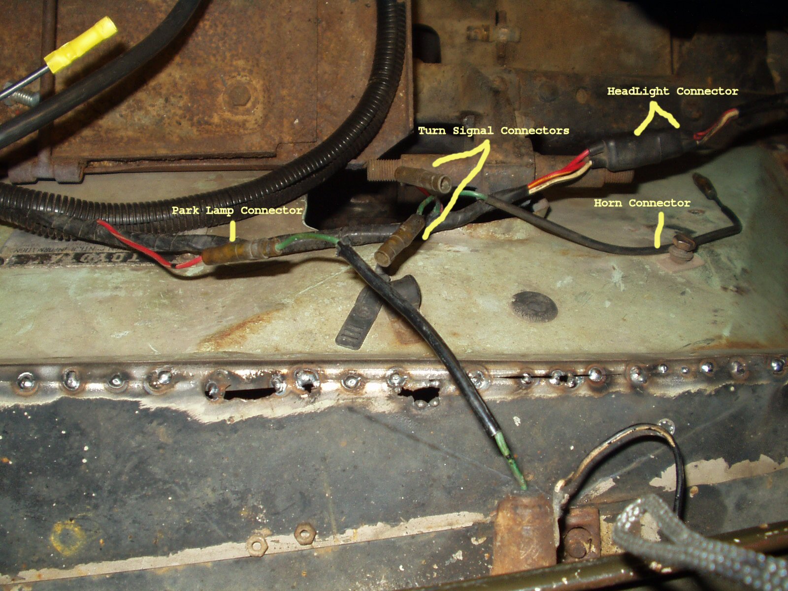
Fig. 8
Head Light same as Drivers side
Horn same as Drivers side
Turn Signal Same as Drivers side
Park Lamp same as Drivers Side
Three Terminal Plug all Female
| Terminal |
Color |
Relay Terminal |
Destination |
| Top terminal | Green/Red | S | Horn Button |
| Left Terminal | Green/Yellow | B | 20 Amp Fuse |
| Right Terminal | Green/White | H | +12V To Horns |
Table 12
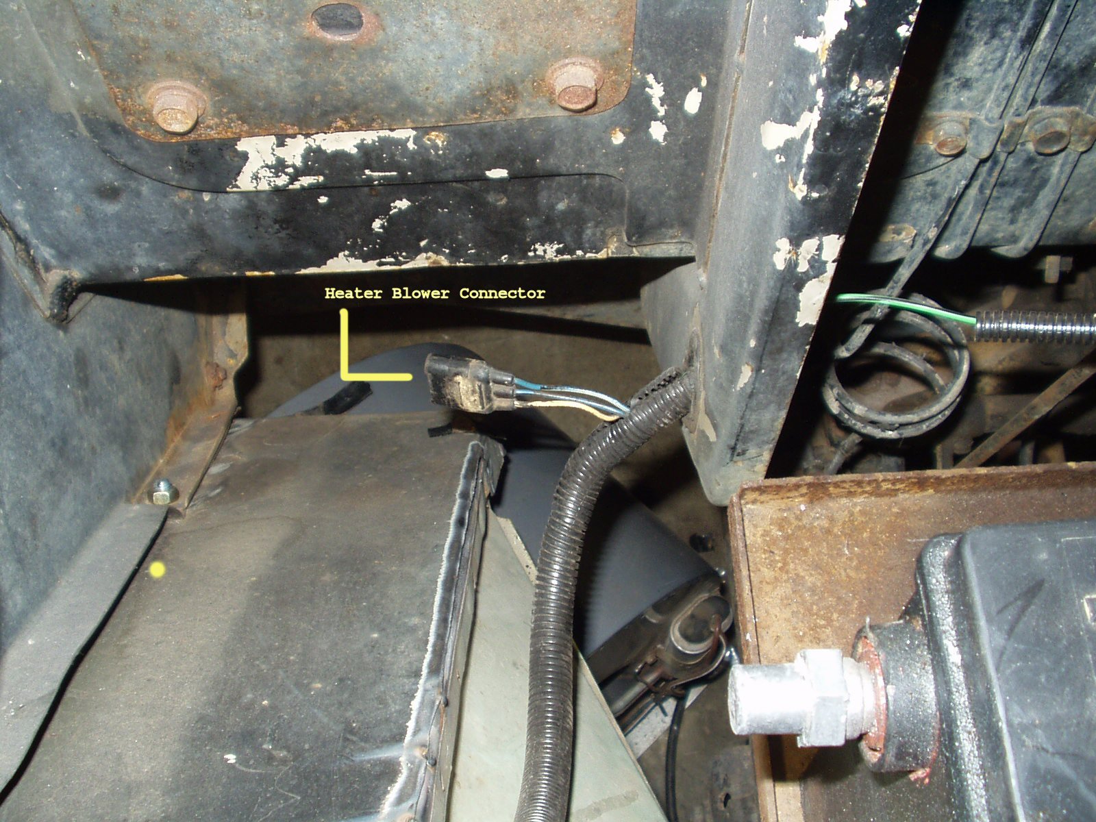
Fig. 9
| Terminal |
Color |
Function |
Destination |
| Male Pin | White/Black | Ground | Ground |
| Female Pin 1 | Blue/Black | High Speed | To Heater Switch |
| Female Pin 2 | Blue/White | Low Speed | To Heater Switch |
Hosted by Global Software, Inc.
©1998 - 2023 Mark C. Baker Web Designer
Please: No part of this web site may be used without express permission... email mbaker@globalsoftware-inc.com for permission.