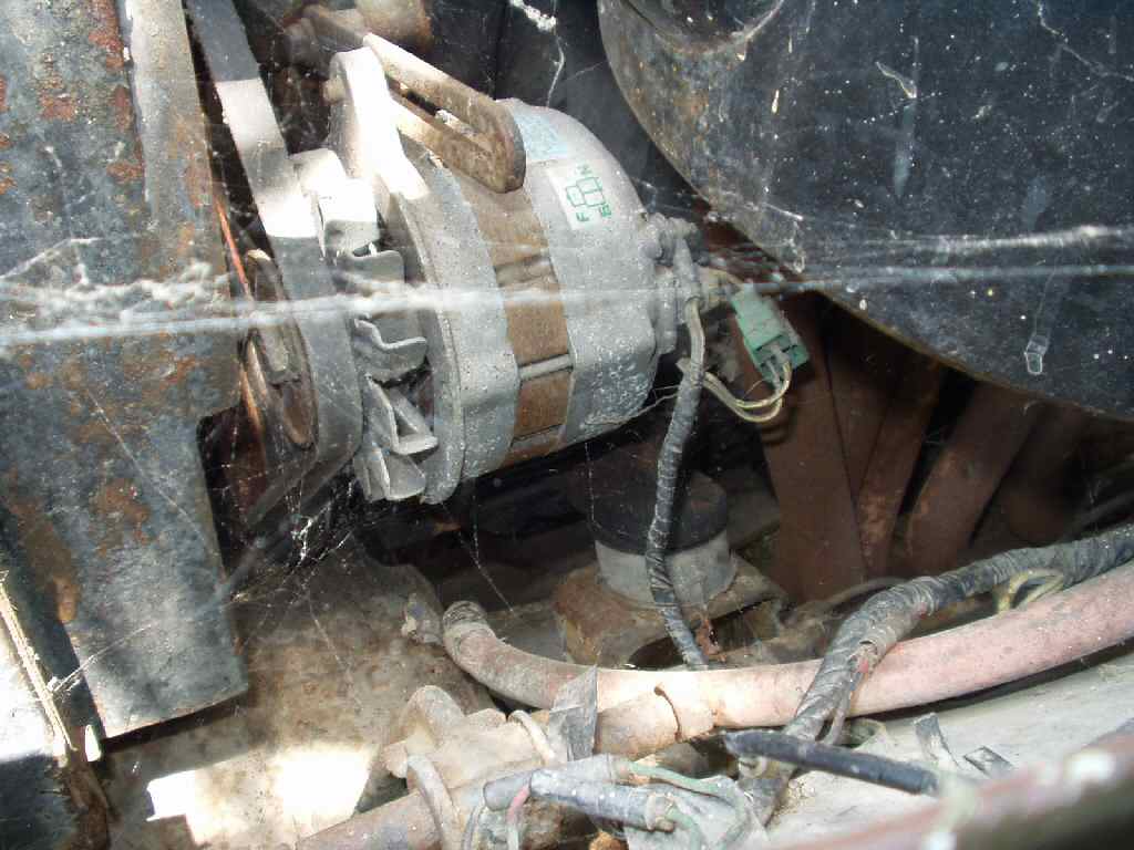
If you have kept up with this build you probably already know
that I have a 1F engine that I am installing mini-truck power steering on.
This meant that I had to use a 2F water pump, FJ60 crank pulley, 2F 6 blade
plastic fan AND had to move the alternator from the driver side to the passenger
side.
I had
already mocked all this up while the engine was still in the frame but now
the engine is on a stand and I can pull all the old cruddy stuff off,
rebuild it and make it shine!
Disassembly
Fig. 1
Removing Pulley
Fig. 2
Pulley Parts
Fig. 3
Removing Case Screws
Fig. 4
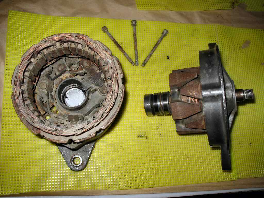
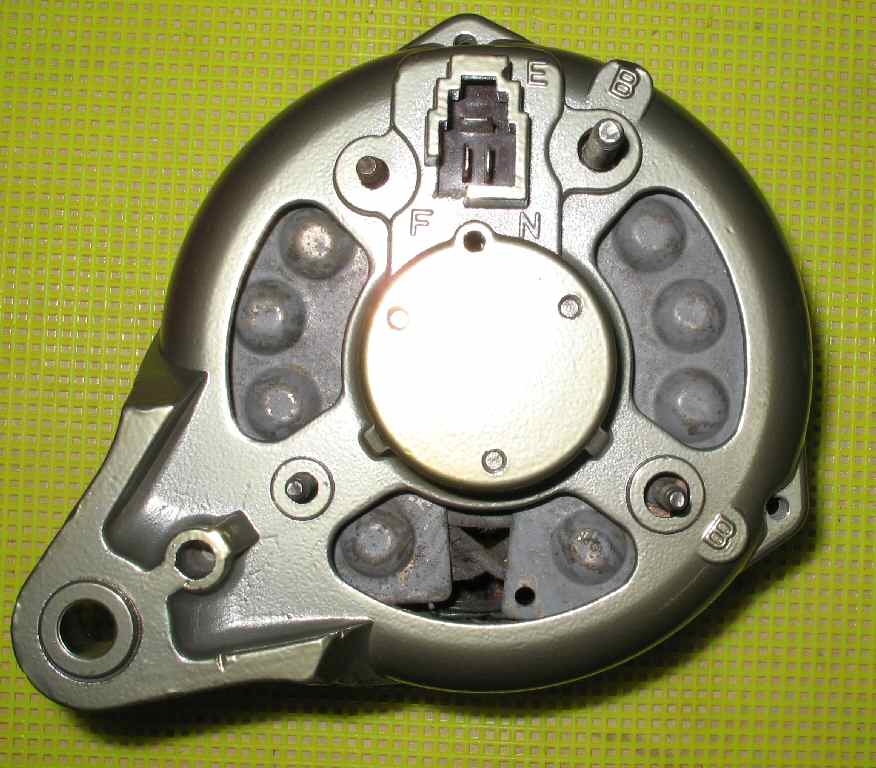
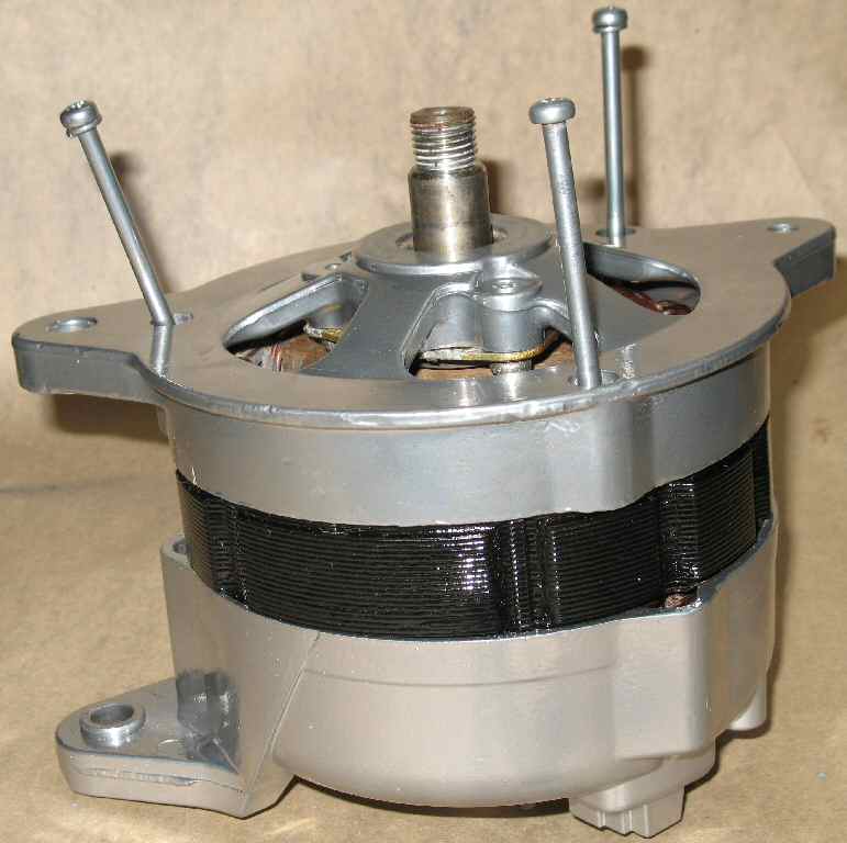
Front Housing/Rotor Removed
Fig. 5
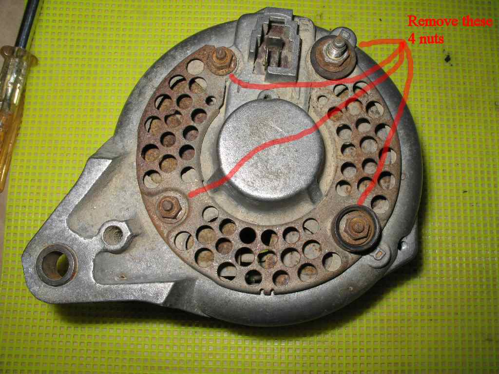
Remove these nuts
Fig. 6
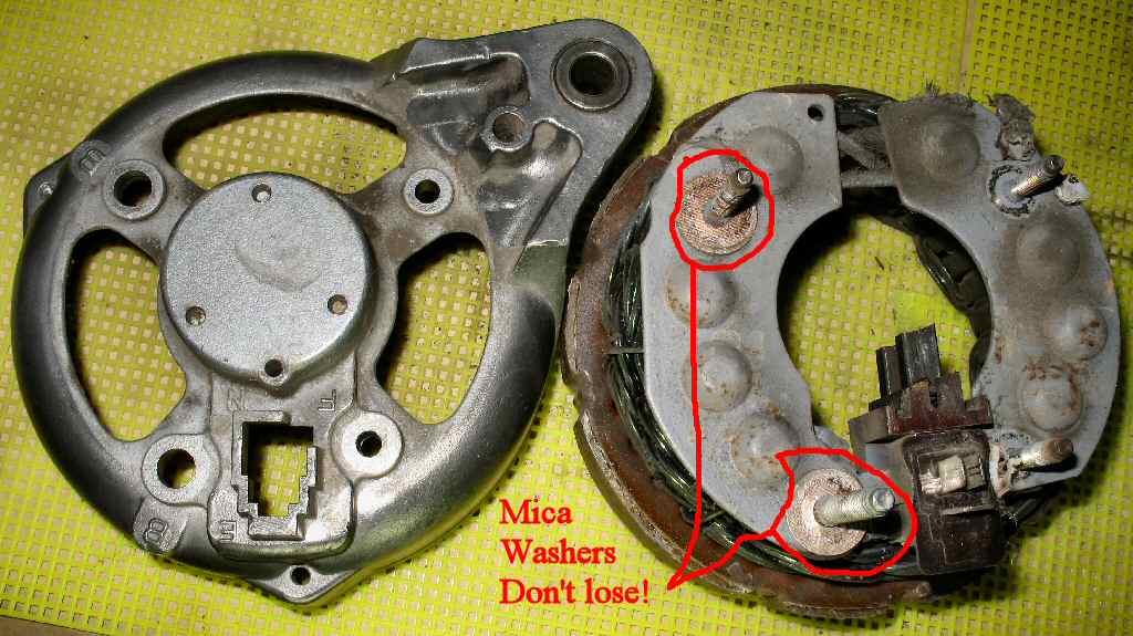
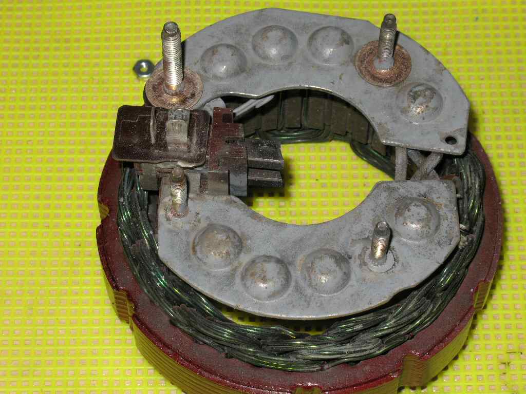
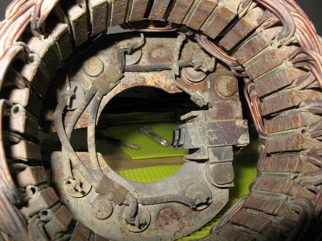
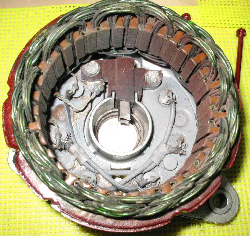
Stator/Rectifier Removed
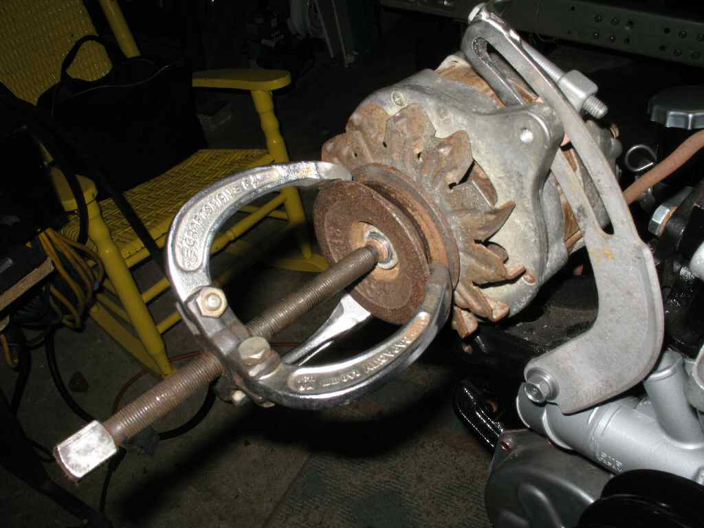
Ok we start by using a puller to remove the fan pulley as shown
in Fig.1. I don't recommend
this method if the pulley is not cast, if it's the thin stamped pulley
and it's
really stuck on the shaft the puller will deform the pulley. If yours
is stuck then apply some penetrating oil and start some light tapping
with a hammer.
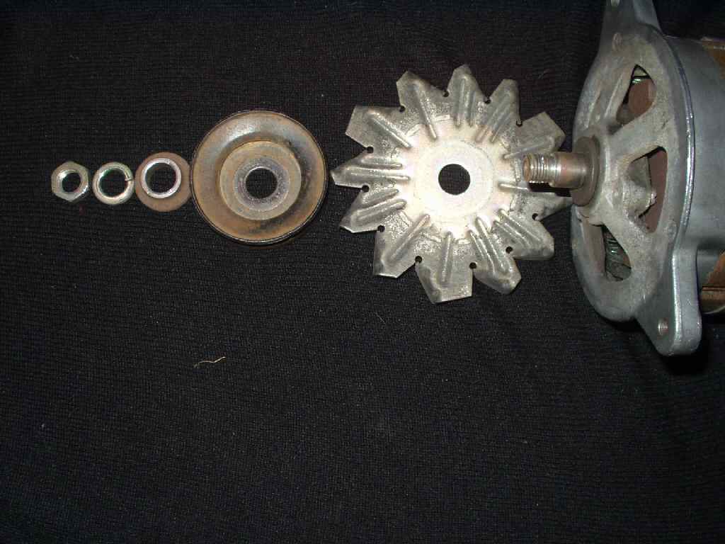
Anyway, Fig. 2 shows the parts in the order
they come off and go back on.
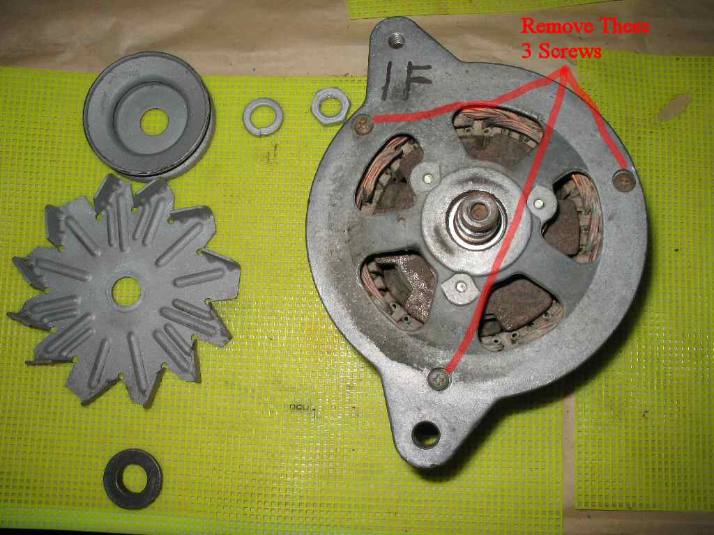
Now get your JIS #2 phillips screwdriver
or a standard #2 bit for your impact driver and remove the three case screws
shown in Fig. 3. If you break these off your
screwed, so if it even looks like the head is starting to strip out, STOP!
Apply some penetrating oil
and if you aren't using an impact driver GET ONE NOW!
Remove the top housing and rotor. If if does not want to
come apart easily use a plastic or rubber mallet on the case. DO NOT hammer
on the mounting ears! This is an aluminum case, they WILL break! Set the
top housing aside. See Fig. 4. Note that
the front housing bearing is usually stuck to the rotor shaft so they
com out as one unit.
Invert the bottom half of the case as shown in Fig.
5. Use
a 8mm and 10mm wrench or socket and remove the four nuts as shown. Remove
the two plastic insulators then lift the ventilation screen off. Use the
rubber or plastic mallet and tap on the side of the stator to break it
free from
the case. Lift the case off. See Fig. 6.
If you notice in Fig. 6, there are two mica washers on one
side of the rectifier but not the other. Do NOT lose these and make SURE
they go back on the same studs if they fall off! Failure to observe this
WILL result in a dead short in the alternator when the battery is connected...
Disassembly Continued
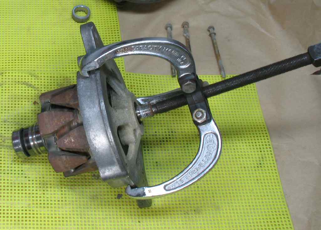
Fig. 7
Removing Rotor
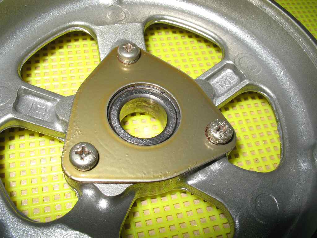
Fig. 8
Removing Front Housing Bearing Retainer Plate
Fig. 9
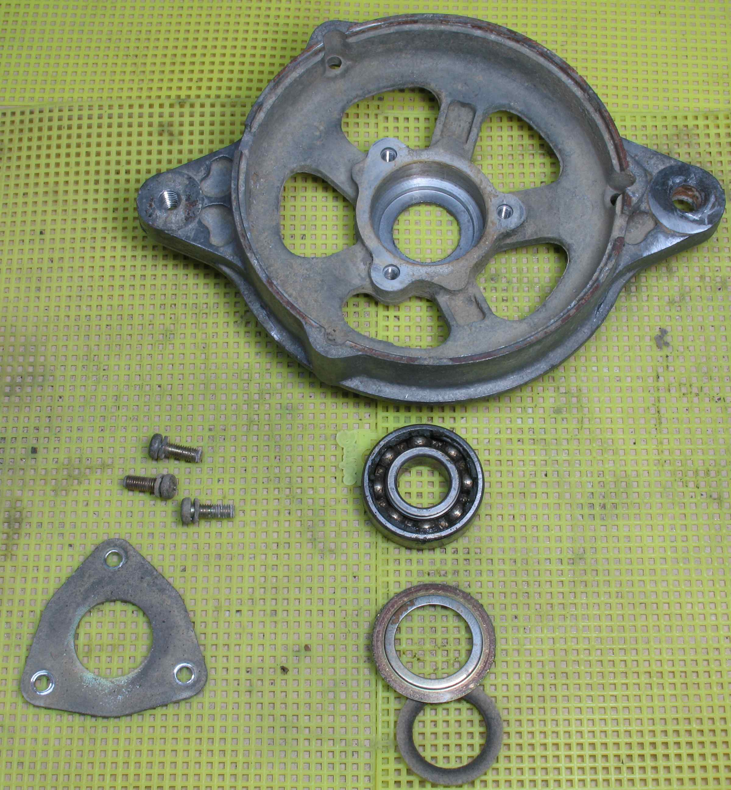
All the parts
Fig. 10
Cleaned Parts
You can use the puller to remove the rotor from the front
housing but the preferred method is to use a press. Mine was not stuck
so I used the puller. Just be aware the front housing is aluminum! See
Fig 7.
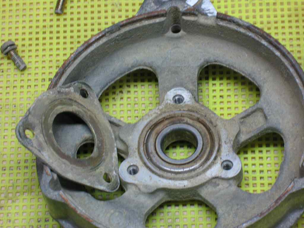
Lay the front housing on it's back and refer to Fig.
8.
Use the impact driver to remove the three phillips screws holding the
bearing retainer plate. Remove bearing shield, then flip the housing over
and use a small screwdriver handle as a drift and tap the bearing out of
the housing. If the felt washer did not come out of the housing, remove
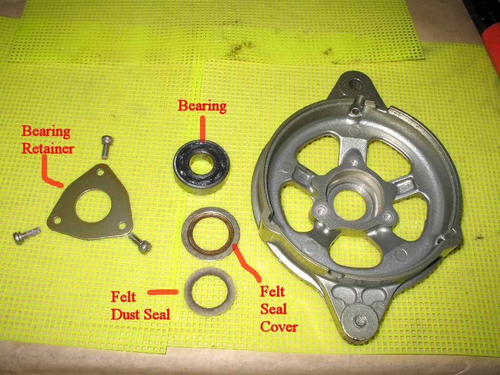
it now. See Fig. 9 for all the parts laid out.
I used my sand blaster to clean all the parts
up and prep them for powder coating. If you plan to do this make sure to
make sure to mask off the bearing cavities. You don't want the surface
of these to be rough. Also mask them off so paint or powder coating does
not get in them. See Fig.
10.
Brush Inspection/Removal/Replacement
Fig. 11
Stator/Rectifier
Fig. 12
Dirty!
Fig. 13
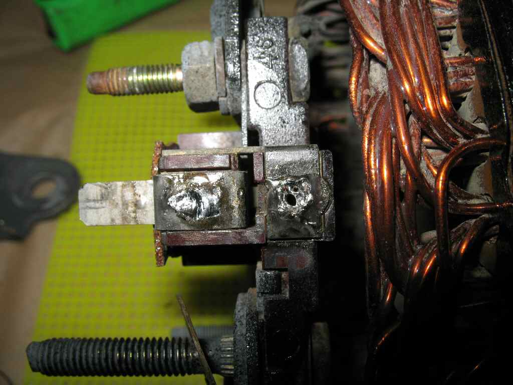
Brushes
Fig. 14
Removing Brushes
Fig. 15
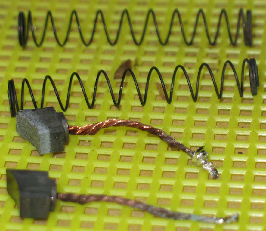
Removed Brushes/Springs
Fig. 16
New Brushes
I was actually rebuilding TWO alternators at the same time.
A 2/71 1F and a 1976 2F, My 71 brushes were in good shape (Fig.
13.) but
the 2F brushes were worn out. (Fig. 15) So
referring to Fig. 11-13, inspect your brushes
and if they are worn so that less than 1/4" sticks out of the housing they
should be replaced.
To replace the brushes you will need a soldering gun and
a new set of brushes. These can be ordered from your local Toyota or C-Dan. The OEM part number is 27371-31011. They are $9.56 a pair.
If you want to order them someplace else they are 8mm wide x
5 mm thick x 15mm long with the wire coming straight out the
rear.
Auto Zone Beck Arnley # 178-1376 $14.99 a pair and
they are special order. (These brushes also fit the 1980 Toyota Corona 2.2L
2BL if they don't list the Land Cruiser).
A cheaper Beck Arnley part is # FAX57 for $2.99 each.
Using the soldering iron heat as shown in Fig.14.
Remember these are spring loaded so when you melt the solder they will
fly away
unless you stuff a rag in the stator to catch them!
To install the new ones, slip the spring over the brush,
feed the wire into the brush housing and out the hole. Grab the wire with
needle nose pliers and pull the brush back into the housing compressing
the spring until you cannot see the bottom of the brush. Now solder the
wire and clip off the excess. See Fig. 16.
I used a soft
bristle brush and soap and water to clean the stator. Just be careful
and don't nick the wire and remove any of the coating! Next I painted
the stator gloss black and set it aside.
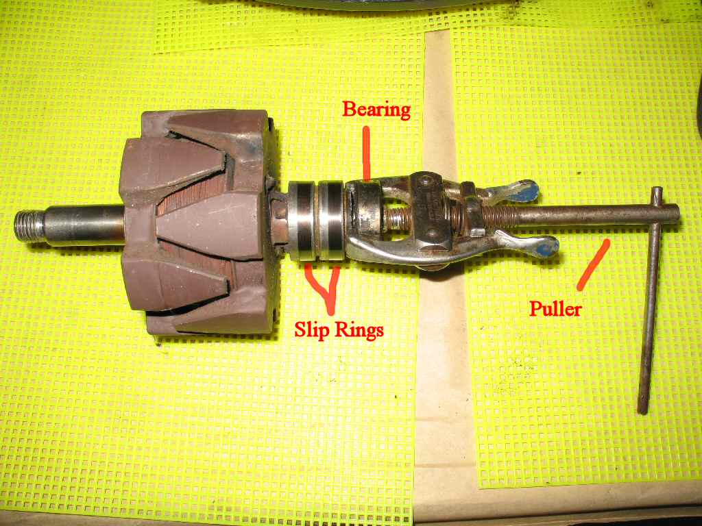
Rear Bearing Removal/Greasing
Fig. 17
Fig. 18
Fig. 19
Refer to Fig. 17 and using
a small puller remove the rear rotor bearing. Clean the shaft and set aside.
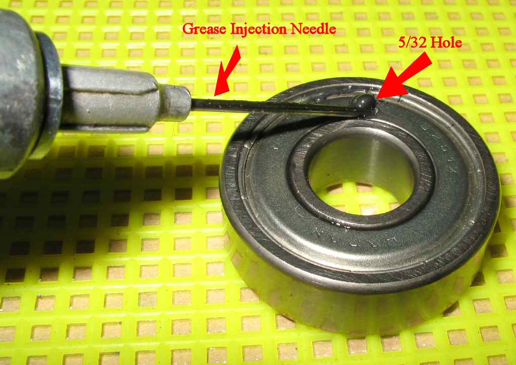
Check the bearing for rust, contamination, roughness and
binding. If in doubt take the bearing to a bearing supply place or an
alternator repair shop and get a new one. The rear bearing is a 6201Z and
is a sealed
bearing. You can get it here: http://tinyurl.com/2dcg7h. If the bearing
just needs a bit of grease then you can drill a 1/8" hole in the shield
and use a grease needle to inject new grease. Don't
overfill it, just a shot or two will be enough. See Fig.
18.
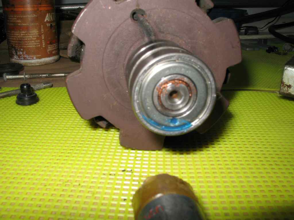
Use some silicone to seal the hole you drilled then tap
the bearing back onto the shaft. See Fig. 19.
Set aside.
Reassembly
Fig. 20
Fig. 21
Fig. 22
Fig. 23
Fig. 24
Gather the front housing parts as shown in Fig.
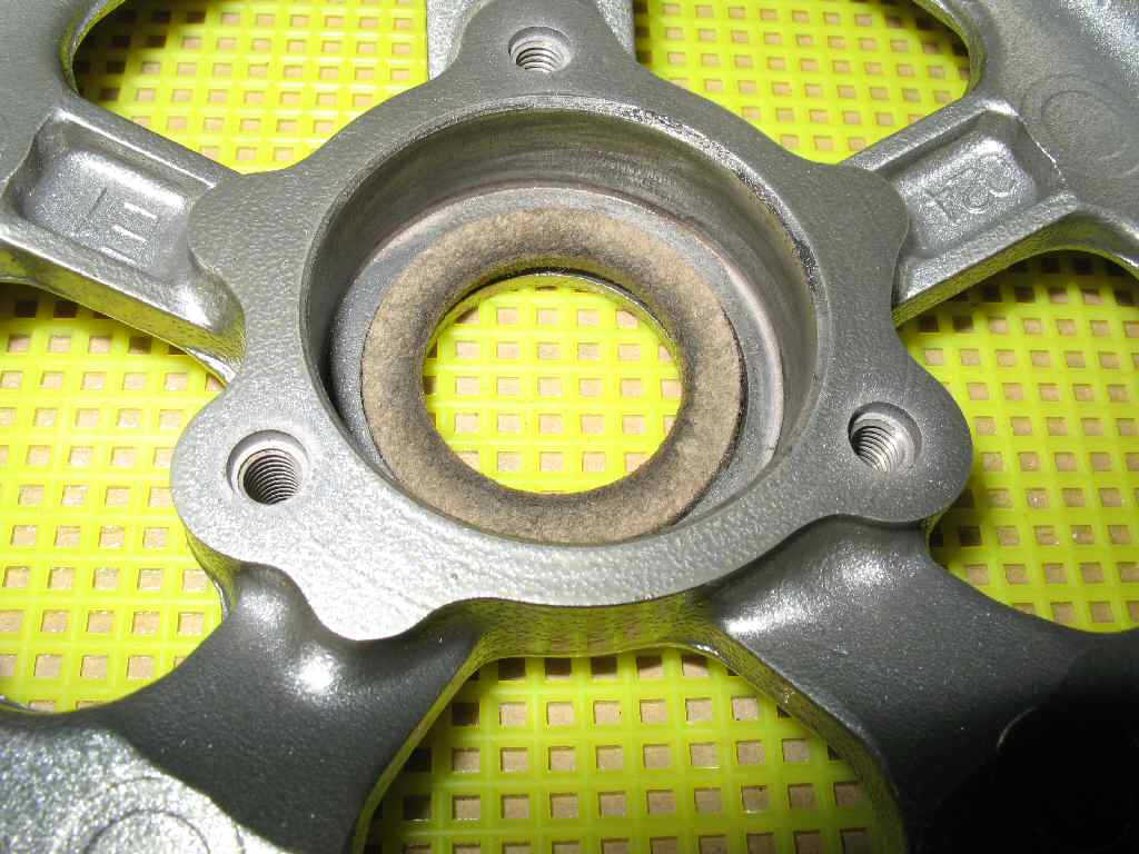
20. Wash the felt washer, (dust seal) let it dry then put several drops
of light oil on it. Insert it into the housing as shown in Fig.
21.
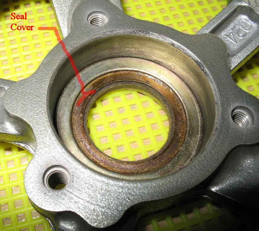
Place the
metal felt cover over the felt ring as shown in Fig.
22.
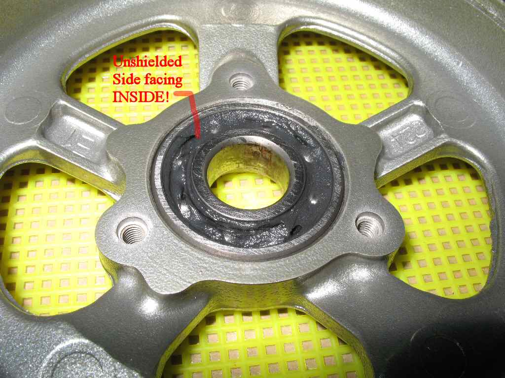
Clean the front housing bearing in solvent, wash in hot
soapy water, rinse and blow dry. (Don't spin the bearing with the air gun,
fun though it is.) Grease the bearing with moly or synthetic grease. Insert
the bearing with the unshielded side facing up as shown in Fig.
23. ( Note if your bearing is sealed and still smooth but needs
grease then follow the instructions in step #15.) If you need to replace
the bearing it is a #6203Z. It is shielded on one side only, non lubricated
Nachi #6203Z (Fujikoshi Steel Industry Co.) :
http://www.vxb.com/Merchant2/merchan...gory_Code=17mm
Install the bearing retaining plate as shown in Fig.
24.
Set the front housing aside.
Fig. 25
Installing Stator/Rectifier
Fig. 26
Back View
Fig. 27
Place Screen
Fig. 28
Secure Stator/Screen
If your stator assembly is full of mud and dirt you need
to clean it. Remove the two mica washers referred to in Fig.
6 and step
5. Clean the stator assembly using a soft bristled brush and hot soapy
water. (A
tooth
brush
works great.)
Rinse
and blow
dry. Be careful not to remove the coating from the wires, they are an insulator
and prevent shorts. Reinstall the two mica washers. At this point you can
paint the stator housing. Just be sure to mask off the wiring of the coils.
Insert the stator into the rear housing as shown in Fig.
25. Flip the housing over and align the rectifier studs so they
come through the housing as shown in Fig. 26.
Place the ventilation screen over the studs as shown in
Fig. 27. Get the plastic insulators and place
them over the two studs shown in Fig. 28.
The bigger insulator goes over the top B stud, the smaller over the lower
B stud. They will only go one way. Secure the insulators
and the other two studs with the flange nuts you removed earlier.
Fig. 29
Fig. 30
Fig. 31
Rotor Inserted
Fig. 32
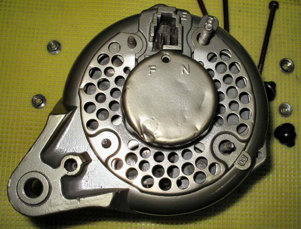
Front Housing Installed
Fig. 33
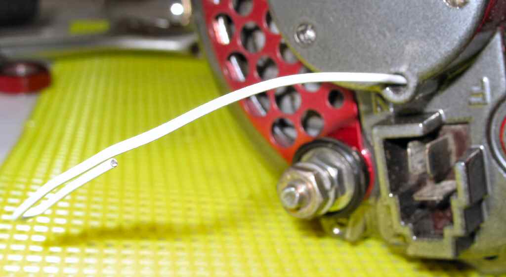
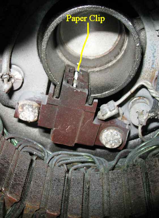
Get a large paper clip or other small diameter but stiff
wire. Insert this wire into the hole in the rear cover just above the wiring
connector as shown in Fig. 29. Reach inside
the rear housing and with another tool press
the
rear
most
brush
into it's
holder until the wire you inserted in the rear passes over top of it. Continue
pushing the wire so that it goes through the small metal tab BETWEEN
the brushes. Now push the front brush into its holder and continue inserting
the wire until it's holding the front brush in place. See Fig.
30 for how
it's supposed to look. This is not as easy as it sounds and may take a
couple or three tries!
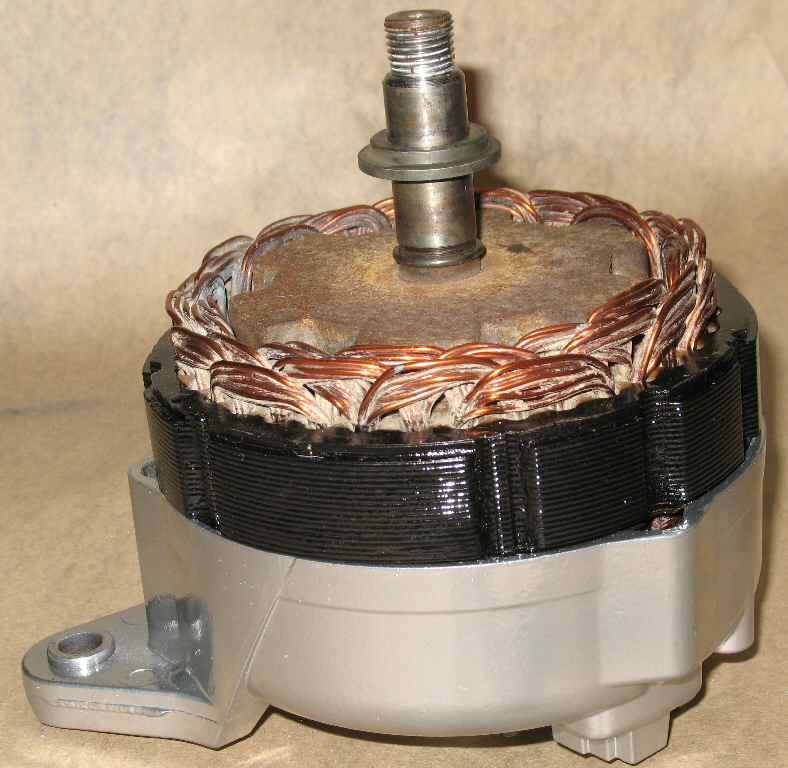
Lay the rear housing flat on the bench and insert the rotor
as shown in Fig. 31. With the brushes retracted
it will slide right in. There should
be a bushing that fits on the rotor shaft before the front housing goes on.
You can see it in Fig.
31.
Place the front bearing housing over the rotor and align
the mounting ears. Put a bit of anti seize on the three case screws and
insert them into the cover. Tighten hand tight only. Place the fan spacer
bushing over the shaft then the fan, pulley, lock washer and finally the
nut. Insert a 6mm allen wrench into the end of the shaft and put a 22mm
wrench on the nut. Tighten firmly! See Fig. 33.
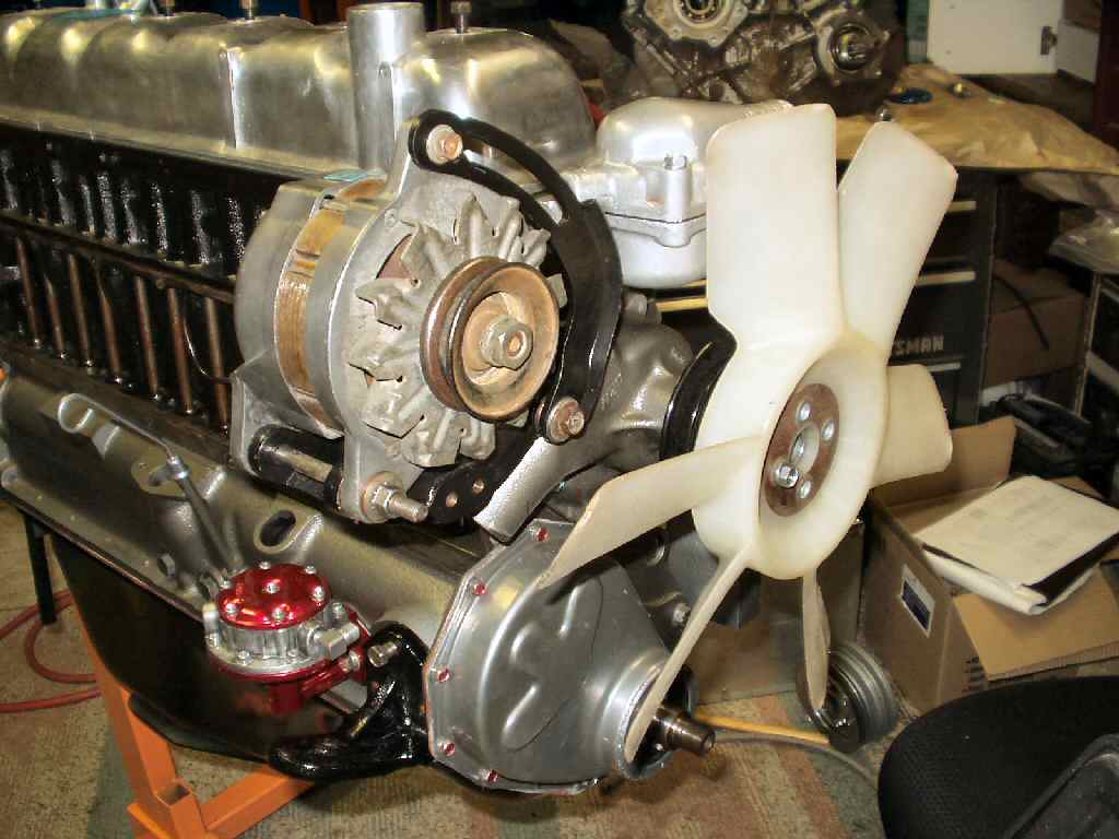
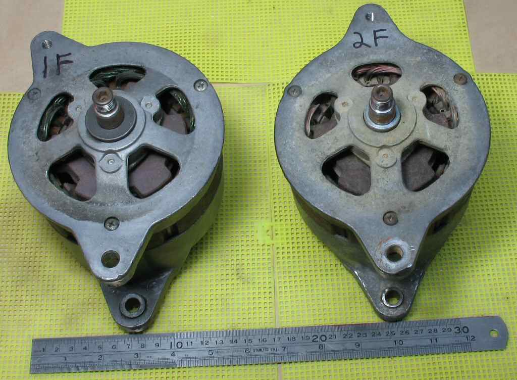
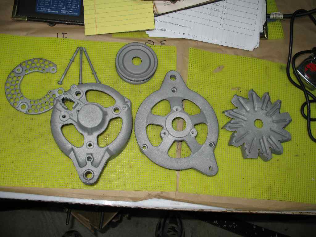
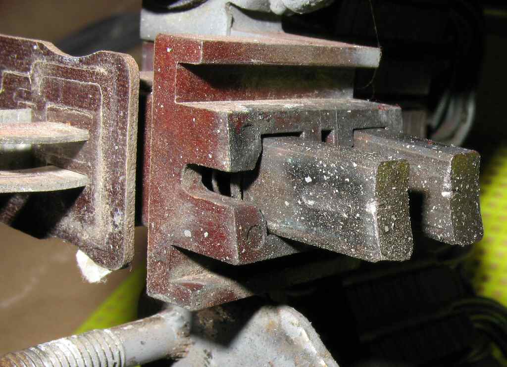
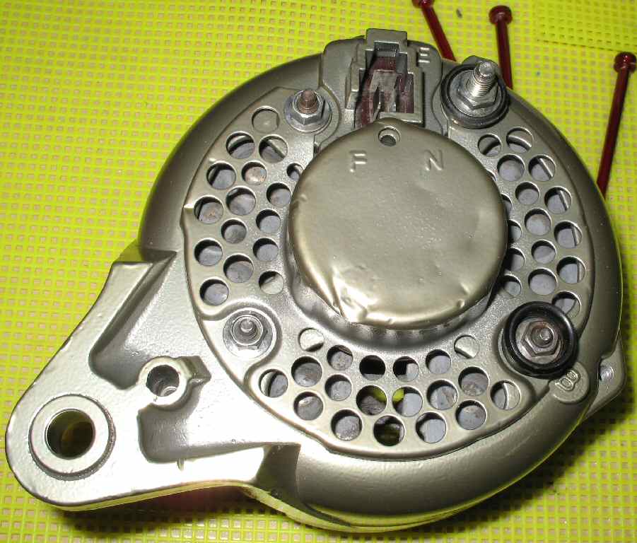
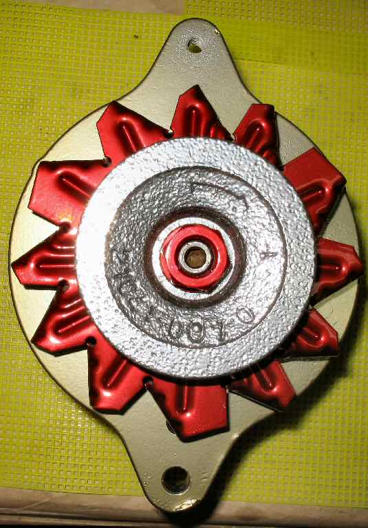
If you plan to use the F alternator on the passenger side using
the 2F alternator bracket you will need to replace the F alternator front
housing with the 2F alternator front housing. It is a direct fit and will
allow the belt to
have
more adjustment room. If does this because it is clocked differently. See pic
above.