Retrofitting a FJ60 Large Cap Dizzy/Igniter
Delco Dizzy Dilemma
**Updated 8-3-2009 **
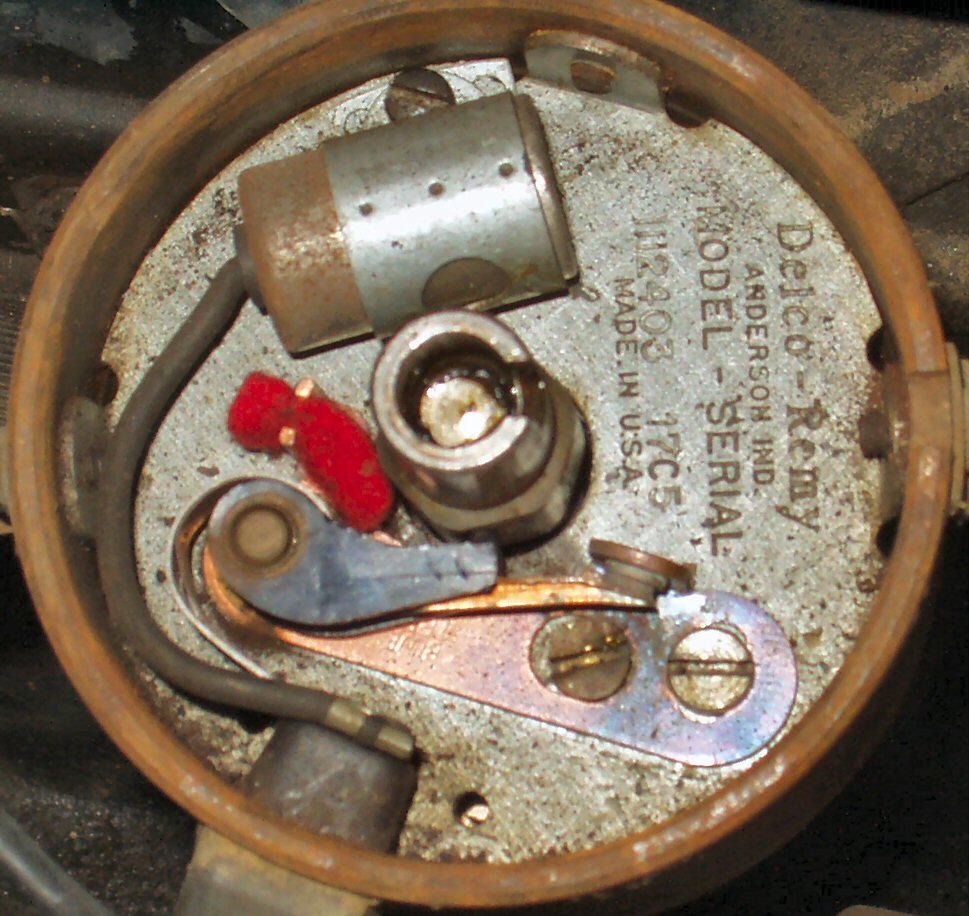
Man-a-not-fre must have given the first PO of my Cruiser (I'm the third) some super good deals. It has the 6 in to 1 headers,(since swapped to Downey 6 into 2 headers), seat covers, grab bar and the one I really don't get, the Delco distributor. This POS distributor has no vacuum advance, burns points quickly (look at Fig. 2, the points are discolored from heat!), and is wearing my cam gear out! Time to pull that sucker out and put back a Toyota distributor.
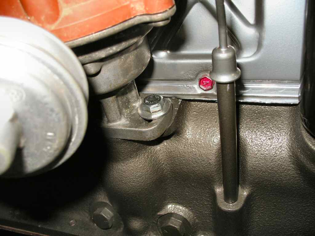
Fig. 1 |
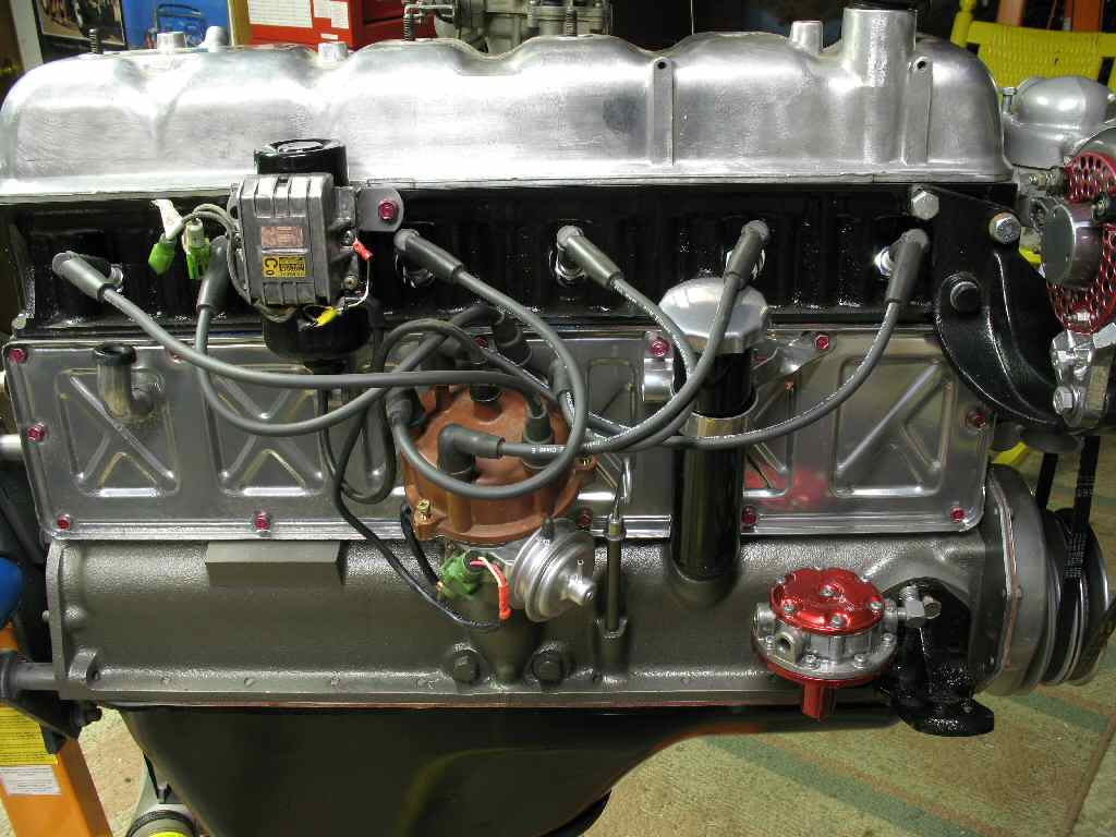
Fig. 2 |
My first attempt at this was to pull the distributor from a spare 1974 motor I dug up and now have. I cleaned it up and took it apart to not only see how it worked but to rebuild anything that needed it. It would have needed a lot. Axial play was out of spec and the upper bushing had severe slop in it. During this process I was continuing to read and learn. What I learned was that this dizzy was a vacuum RETARD dizzy. This style dizzy did come stock on my 1971, but like the Delco, it only has mechanical advance. Plus it has bronze bushings instead of ball bearings and the bushings are not available. Oh well, at least I now know how the dizzy works.
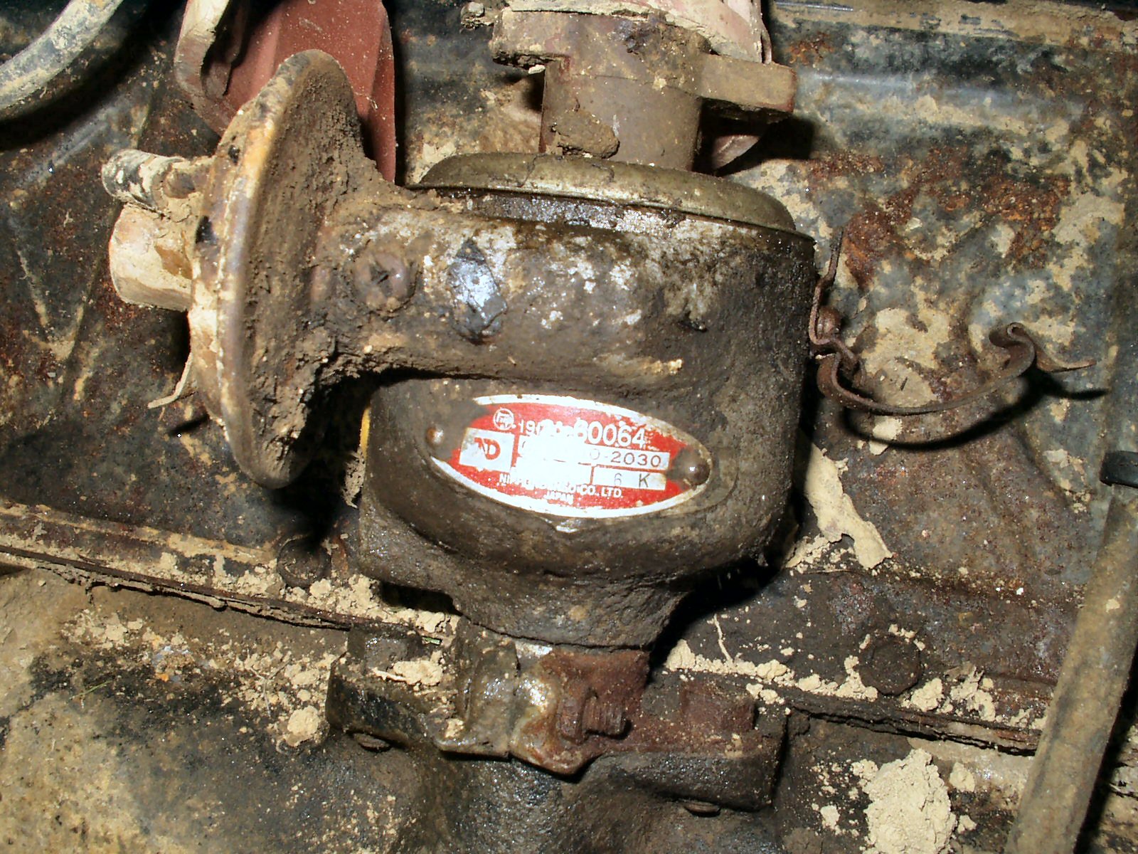
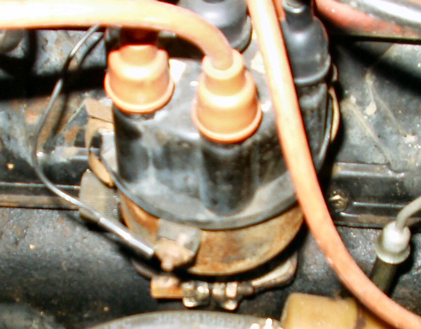
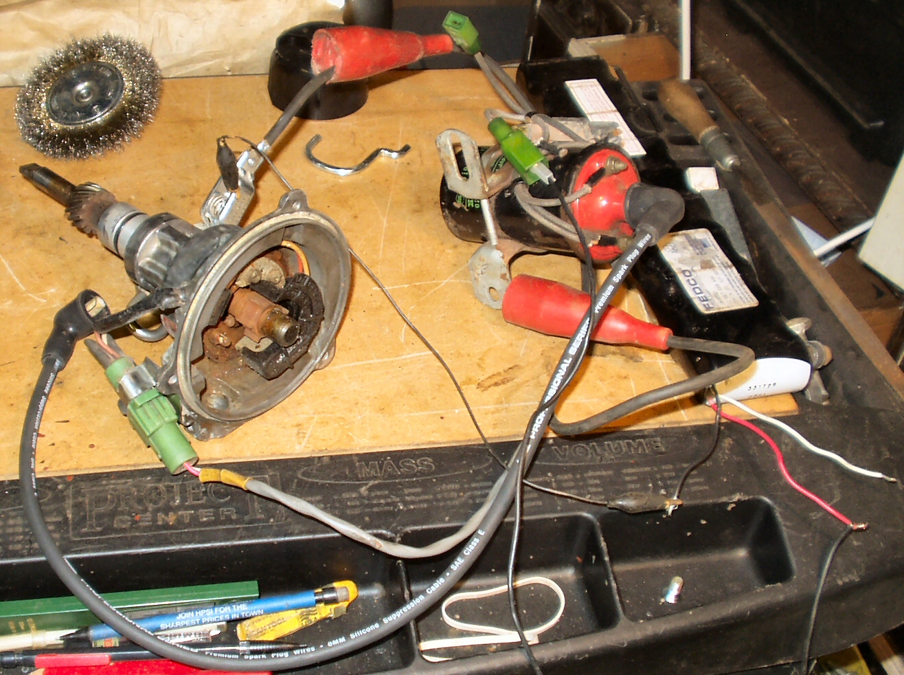
Fig. 3
Dirty Dizzy on 1974 F Engine
Cap off |
Points and Breaker Plate |
Points removed |
Breaker Plate removed |
Advance Weights |
All the parts |
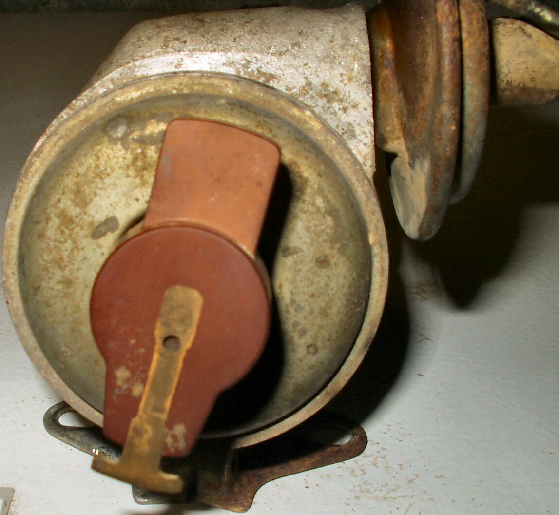
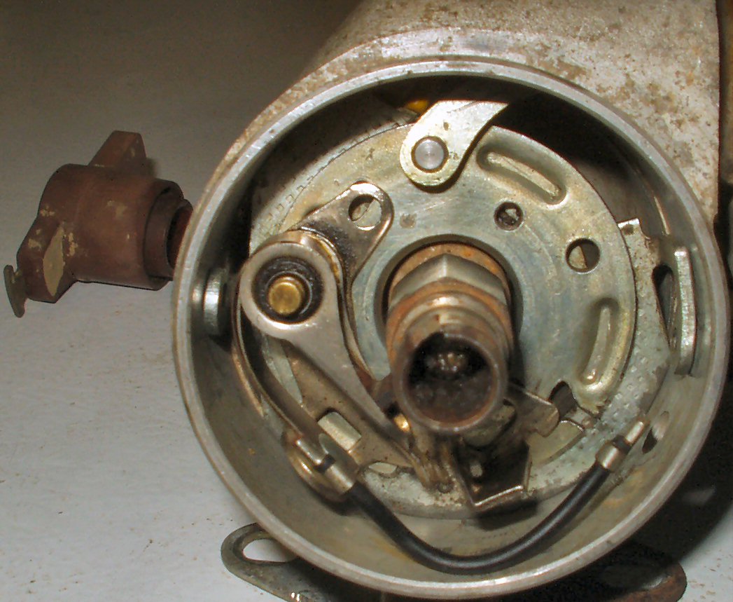
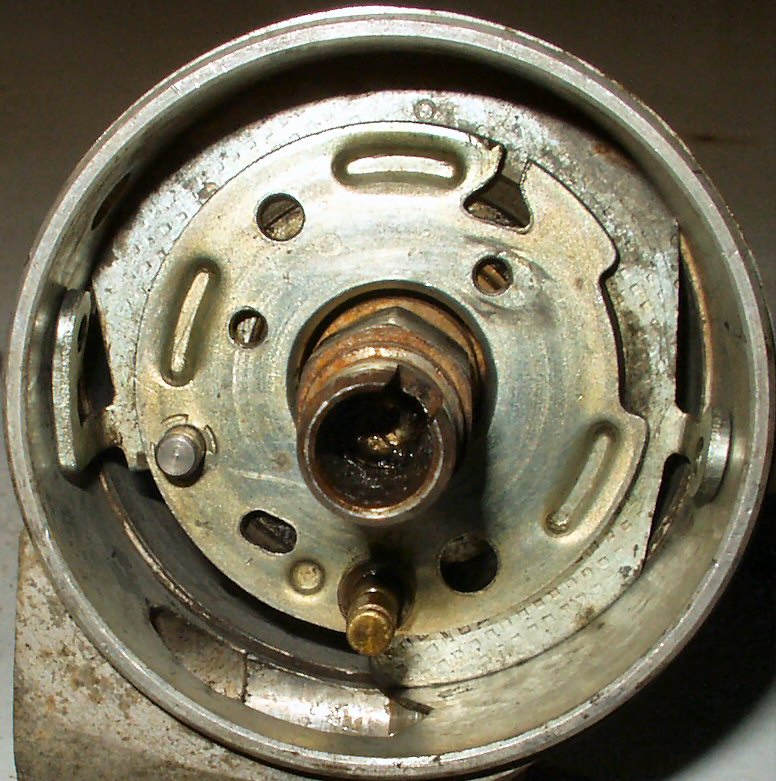
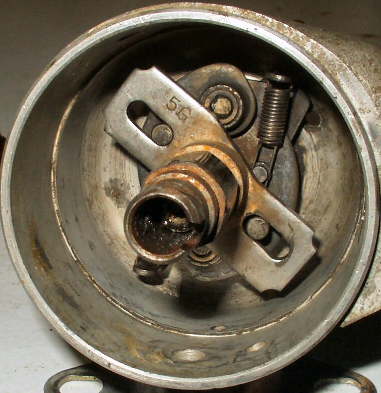
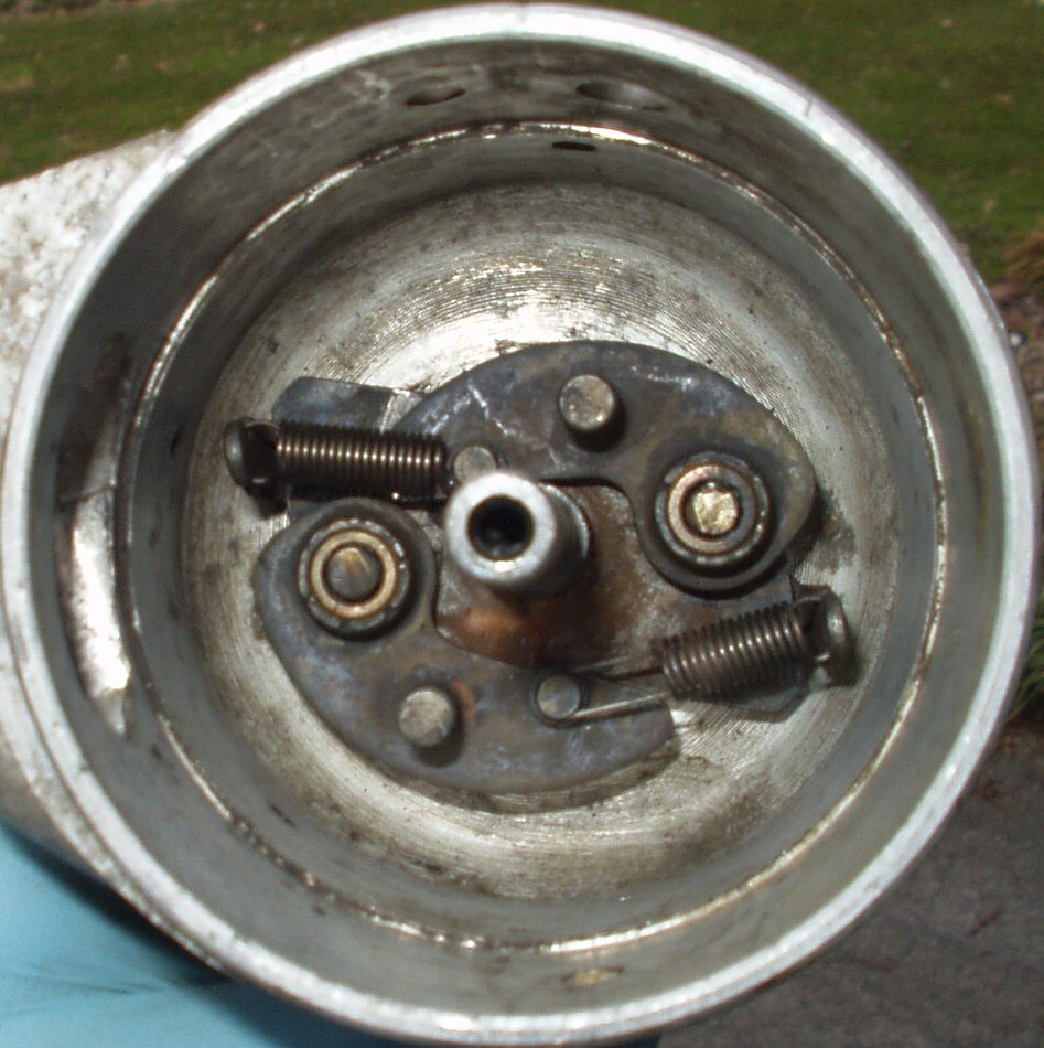
Fig. 4
How the Toyota 1974 Vacuum Retard Dizzy comes apart
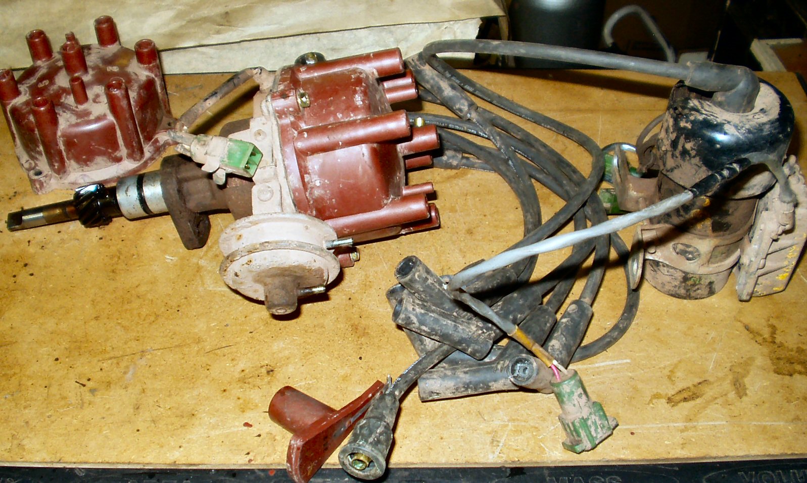
My 'New' Distributor!
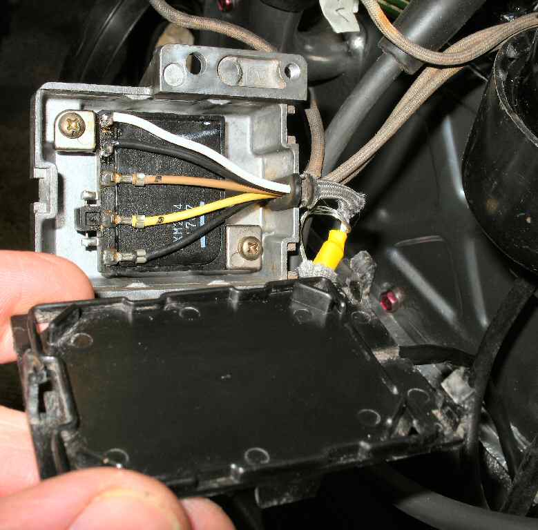
I acquired a 'new ' distributor from a 1987 FJ60 2F motor for a good price. It came complete with an indented side cover.
 |
 |
 |
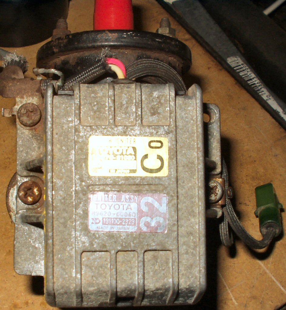 |
Fig. 5
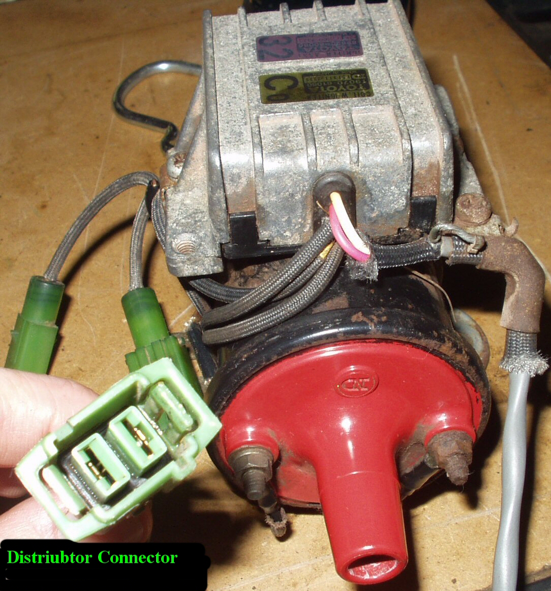
My first task was to test it. Not having a FJ60 FSM I had to read up on the testing procedure on the web. Here is how I set it up on the bench to test it.
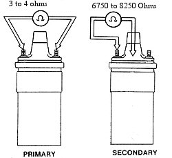
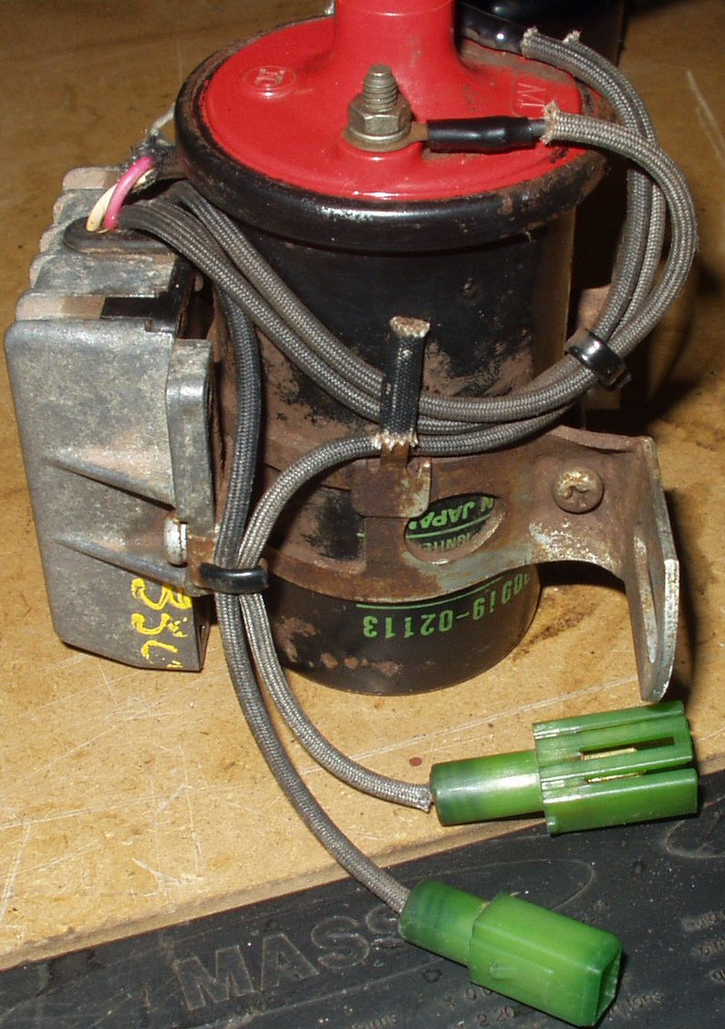
Bench Testing the 79-87 Distributor and Igniter/coil
Fig. 6 Connecting the Dizzy |
Fig. 7 Dizzy Connection |
Fig. 8 Coil/Igniter Connections |
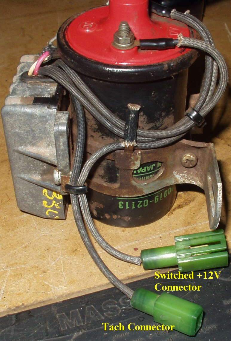
Note: Failure to properly make the following connections correctly will result in a blown Igniter!