Fig. 1
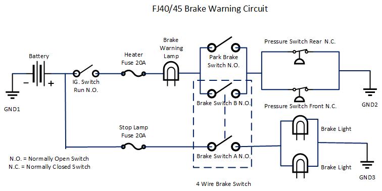
Fig. 2
Of all the electrical things I have examined
and documented on the FJ40 electrical system, this one caused me the most headaches
figuring out. Though this circuit is really simple electrically
speaking, it can be hard to understand how it actually works since there are
hydraulics, mechanics, and electrics all involved together. I will try to explain
this in as simple terms as possible.
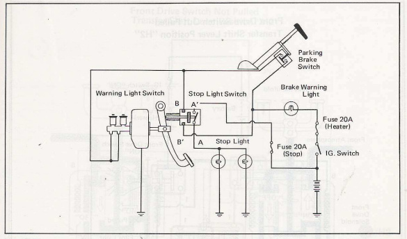
Fig. 1 is a drawing taken from a 1975 Toyota manual and Fig. 2 is my version redrawn in Visio to make it (hopefully) easier to understand.
I'll start with explaining how the OEM Low Brake Pressure Sensors themselves work. The two sensors are simple Normally CLOSED pressure switches. They are screwed into the bottom of the master cylinder so they detect brake fluid PRESSURE in the front and rear brake circuits. When the brake pedal is NOT pressed, ie there is no pressure in the two brake circuits, the switches in the sensors are CLOSED. When you press the brake pedal down further, pressure builds in the master cylinder. When the pressure reaches the set point of the switches, in both brake circuits, they OPEN.
FYI! The correct brake light switch for this circuit is a 4 wire brake switch that contains TWO sets of normally OPEN contacts, A and B. The A set is for the actual brake lights and the B set is for the Low Brake Pressure Warning circuit. Be aware that a lot of aftermarket switches are only two wire and do NOT contain the B set of contacts! Make sure you have the correct switch installed.
Refer to the schematic above. The initial conditions are this: The key switch is on, the brake pedal is NOT being pushed, and the Park Brake is NOT on. The Low Brake Pressure/Fluid Warning Lamp is OFF.
One side of the pressure switches are connected directly to ground through the master cylinder mounting bolts and the other side of the switches are connected to the low brake pressure lamp through the main brake switch. When you first turn the key to on (not start) the Low Brake Warning lamp is NOT on (unless the Park Brake is ON, see below for a description of how that circuit works). At this point, if you LIGHTLY press the brake pedal, two thing happen. First, BOTH sets of contacts in the 4 wire brake switch CLOSE. So the brake lights come on, and for a second, the Low Brake pressure Warning lamp comes on. Why? At this point there is no pressure built up in the brake circuit so the brake pressure sensor switch is still CLOSED and connected to ground. Follow the schematic and you will see that the circuit to the bulb is now complete from ground, through the pressure sensor switches, through the B set of contacts in the 4 wire brake switch, through the bulb and finally to +12V. So the bulb lights. Now if you press a little harder, pressure starts building in the brake circuit to the point that the brake sensor switch OPENS. When the switch opens the lamp goes out.
Now you may be wondering why the lamp does not light up while driving down the road and your foot is not on the brakes? Since the low brake pressure switch has to have enough pressure in the circuit to keep it open, (to keep the lamp from lighting), where does this pressure come from if your foot is not on the brake? In FJ40's with a drum brake master cylinder, Toyota installed what are called residual check valves. The residual check valves do three things. The primary job is to keep 5-12 PSI on the wheel cylinder cup seals. Since there is always 5-12 PSI of pressure in the system, any small leaks in these seals result in brake fluid leaking out instead of air leaking into the system. Air is the system is not good.
The second purpose of these valves is to provide a firmer feeling brake pedal and to keep pedal travel lower. Think of it as pre-pressurization of the system.
The third thing they do is to keep the low brake pressure switch OPEN momentarily. So when you first apply the brakes, the pressure builds up until it passes the rating of the residual valve which then closes keeping the pressure in the system. Overnight the system pressure will eventually bleed off which is why the lamp lights for a second when you first hit the brake pedal. If a major leak develops in the system the pressure falls below the level of the check valve cause the switch to close and the Low Brake Pressure Warning Light will come on when the brake pedal is depressed.
The Brake Low Pressure Warning Light also serves as a warning light to let you know the Park Brake is set. The Park Brake has a single contact, Normally Open, switch built into its mechanism. This switch is wired in parallel with the B set of contacts on the Main Brake Switch. Refer to the drawing above. Here is how it works. When you first turn the key on, and the brake pedal is NOT being pressed, but the Park Brake IS set, there is NO pressure in the brake system, so the low brake pressure sensor switches are both CLOSED. This provides a path to ground through the Park Brake Switch to the warning lamp which now lights letting you know you left the Park brake on...
Note: If you have a habit of putting your foot on the Brake when starting your truck, you may find that, depending on how hard you actually press the brake pedal, that the warning light will not light even if the park brake is on. This is due to the fact that putting you foot on the pedal MAY build enough pressure in the system to open the Low Brake Pressure switches interupting the path to ground for the light. I suggest you first turn the key on before putting you foot on the brake to prevent this.
Hosted by Global Software, Inc.
©1998 - 2023 Mark C. Baker Web Designer
Please: No part of this web site may be used without express permission... email mbaker@globalsoftware-inc.com for permission.