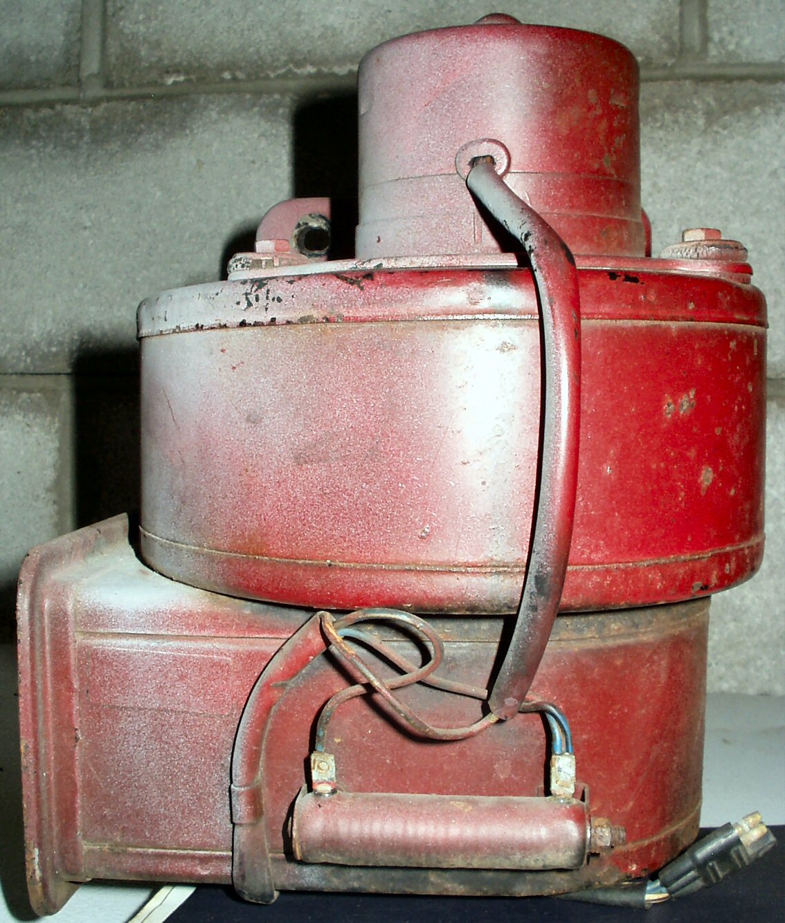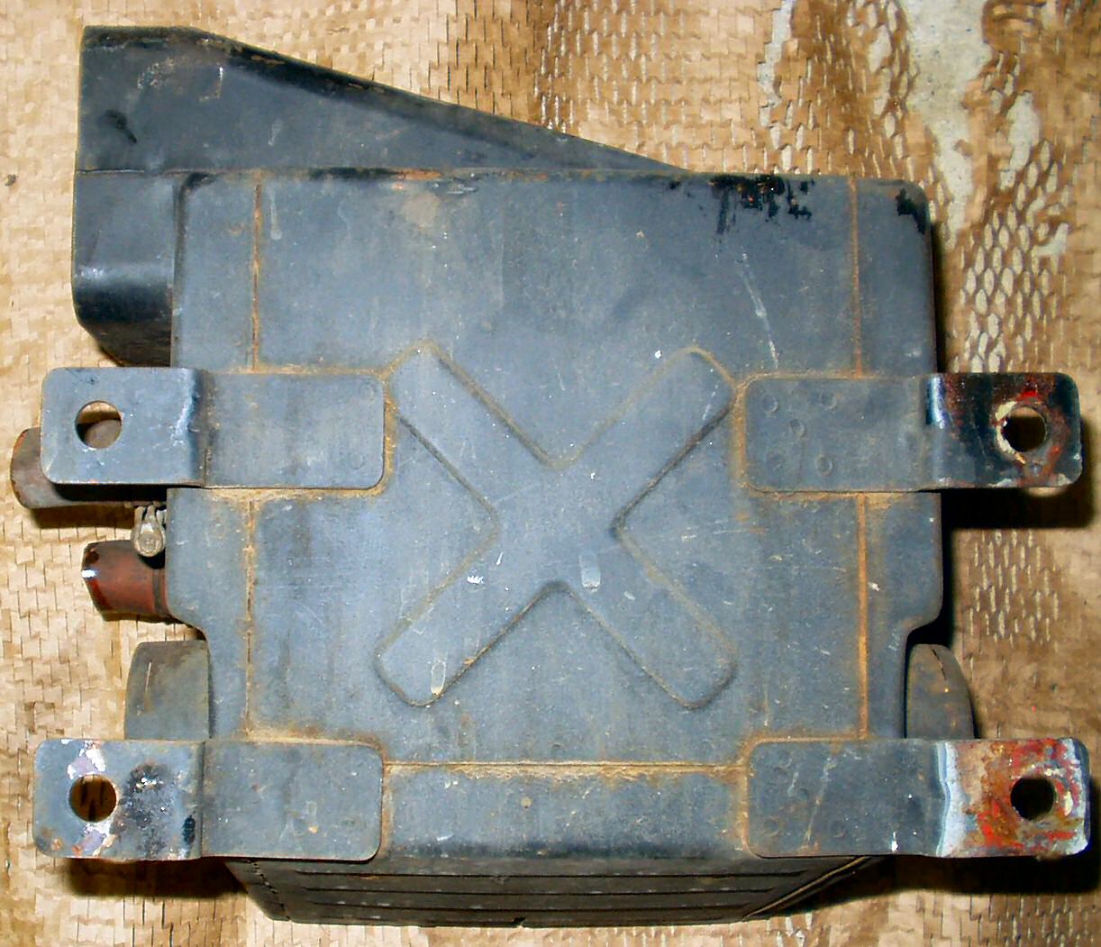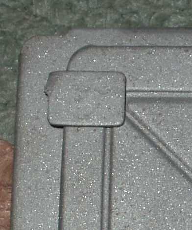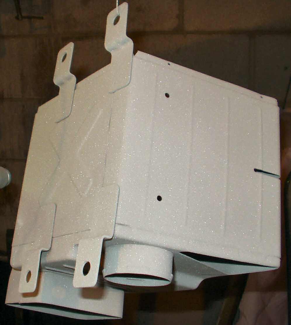
Fig. 1
Front View
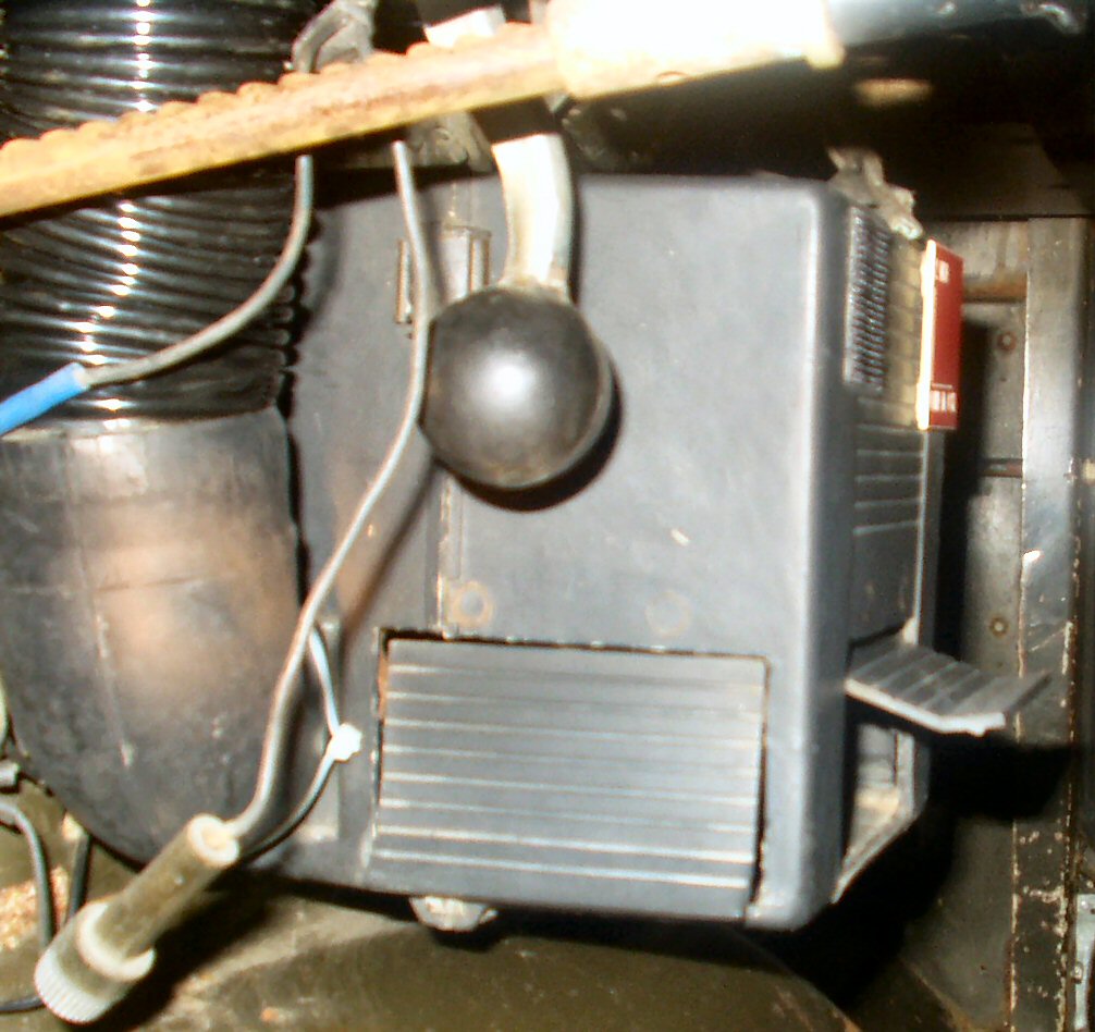
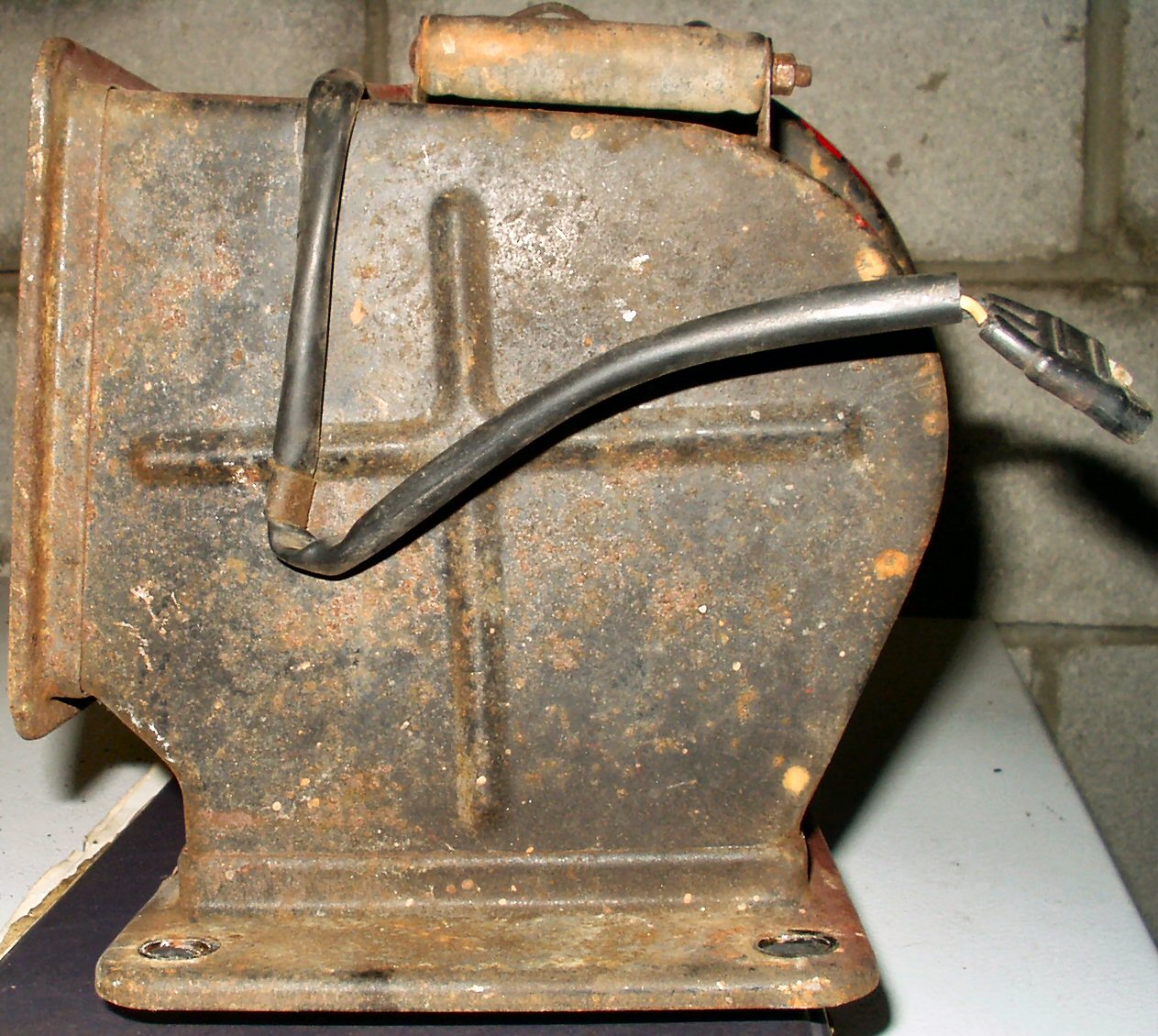
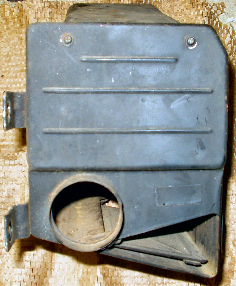
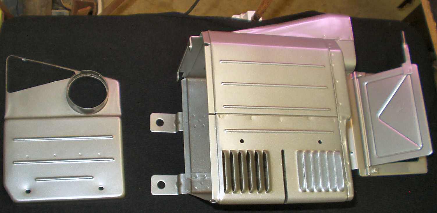
Fig. 2
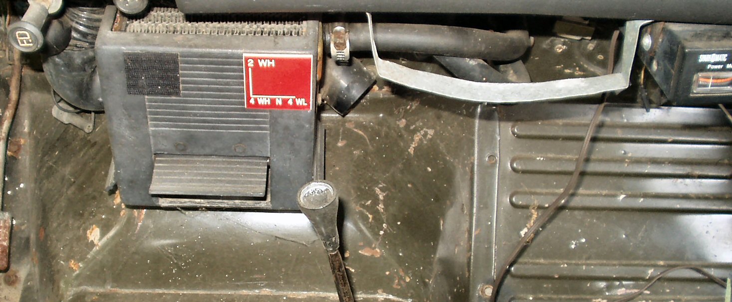
Left Side
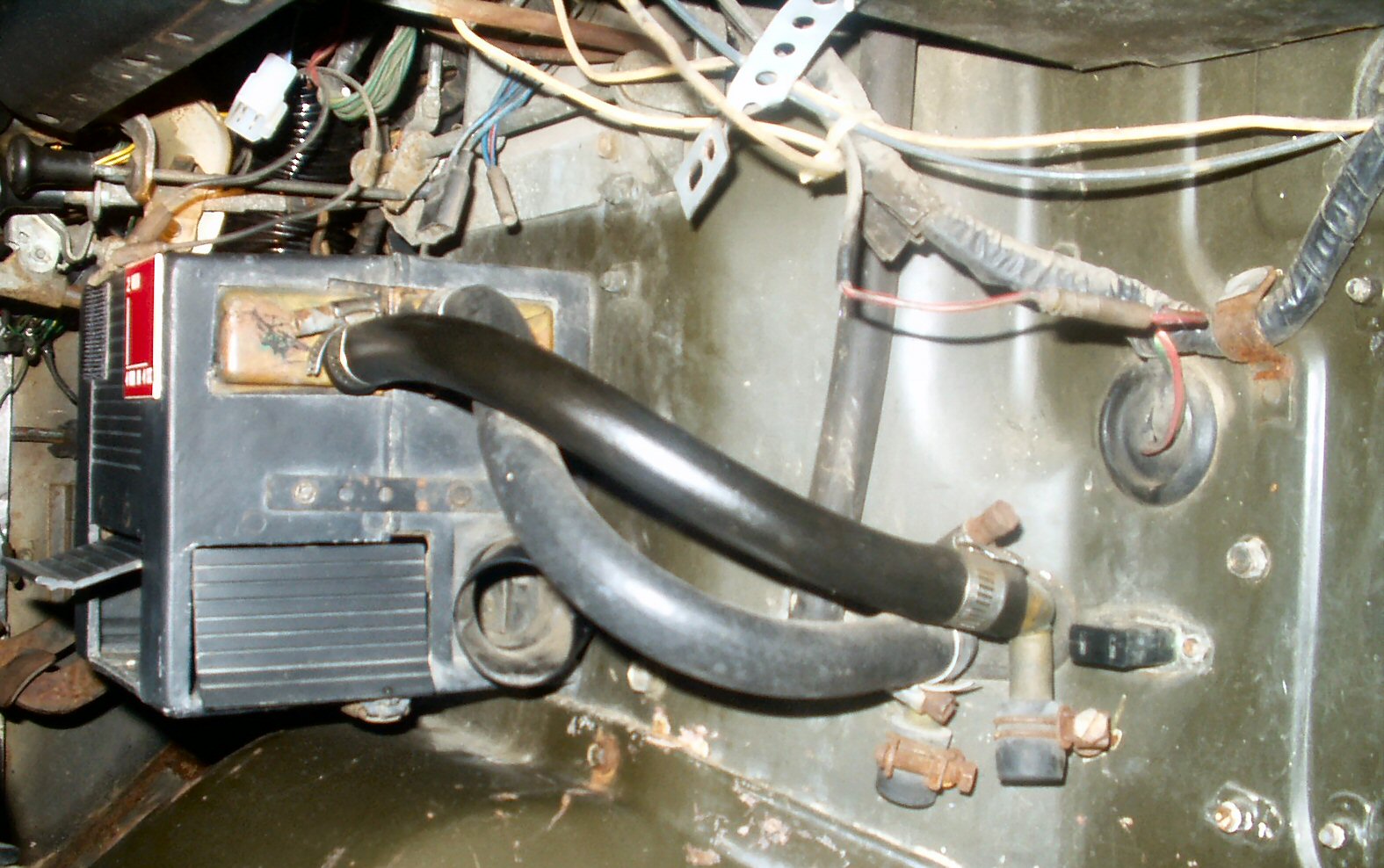
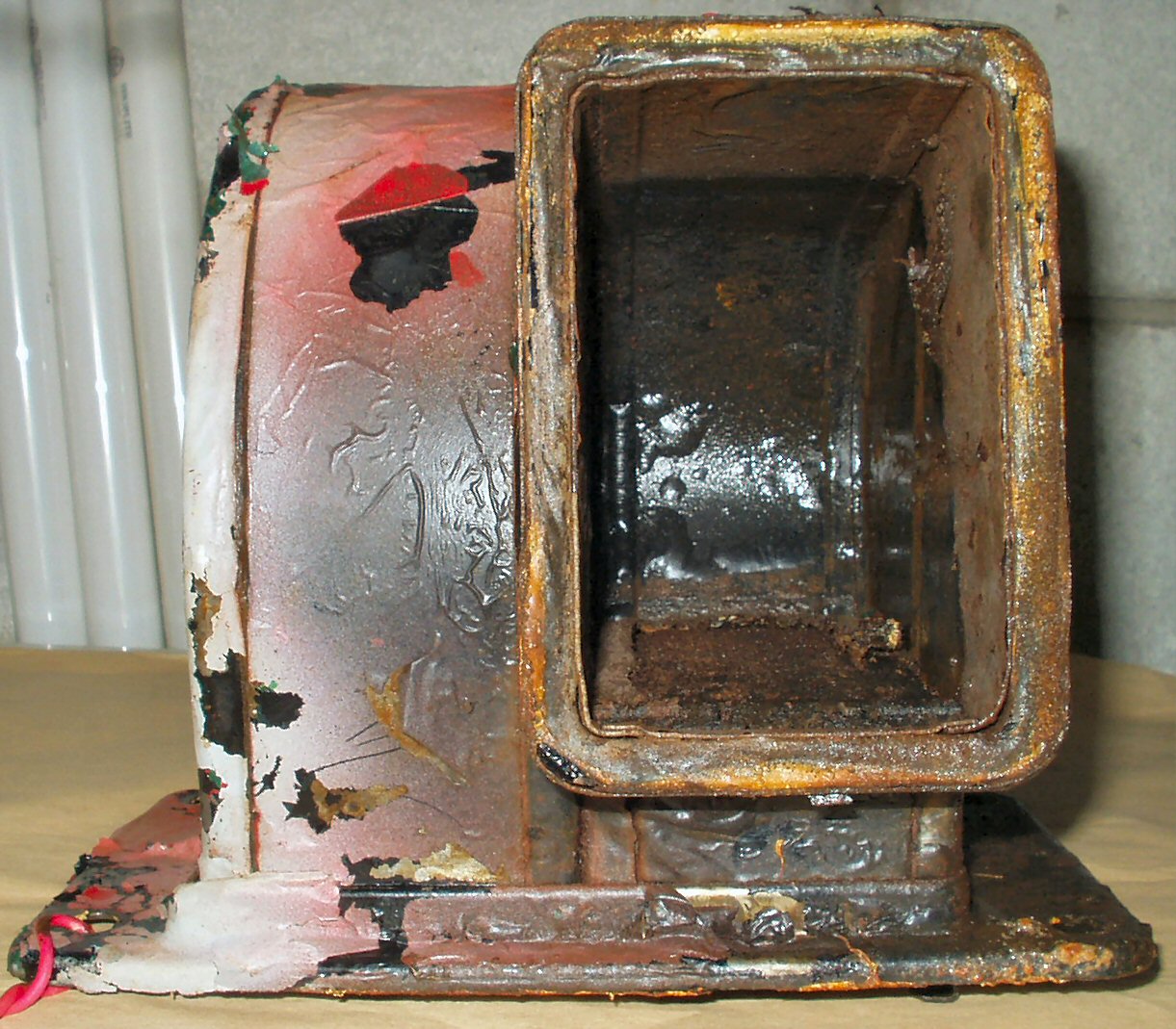
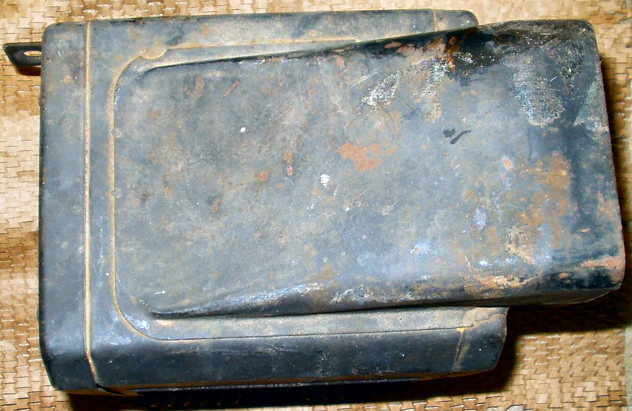
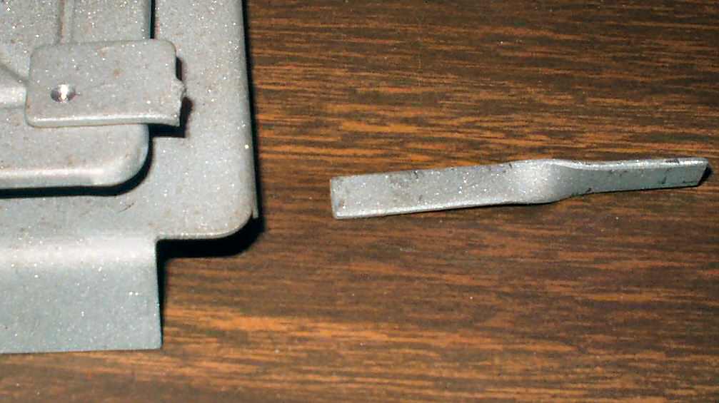
Fig. 3
Right Side
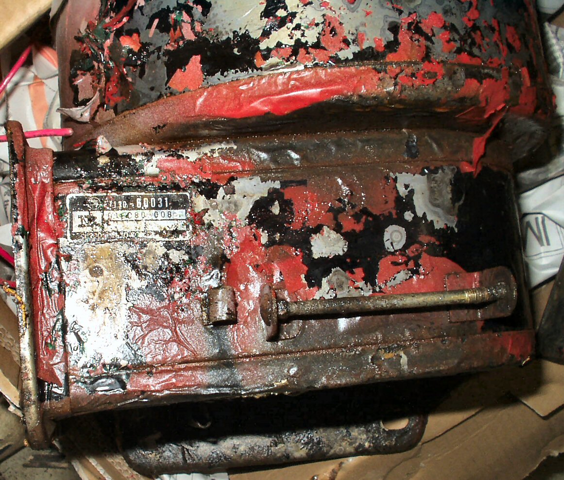
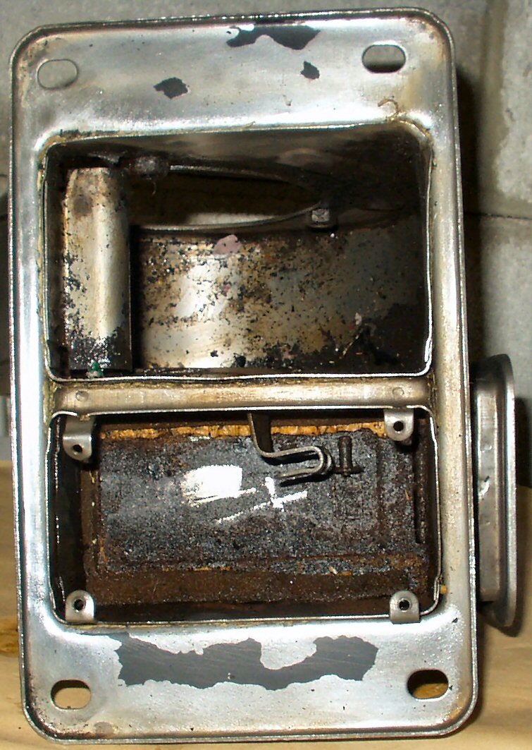
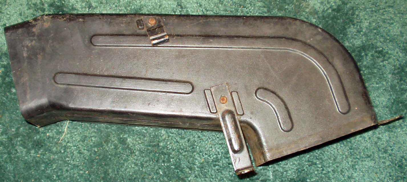
Everyone who owns a Cruiser knows what a front heater should look like right? Well I got to poking around on the web and kept seeing pictures of strange under hood blower motors and under dash heaters in other FJ40's. I got to wondering why they had a different heater than what I had. I mean there was no blower under my hood nor was there any duct work under my dash! Yet when I turned on the heater I had hot air blowing out. Well anyway here is what is currently in my Cruiser: As you can see it's not OEM ... Damn PO's ...
Fig. 1 Front View |
Fig. 2 Left Side |
Fig. 3 Right Side |
When I finally determined that the 1st owner of the truck had, for what ever reason, stripped out all the OEM heater stuff and hand made what you see I was puzzled as to why. Maybe he wanted more leg room under the dash? He did a good job of making this thing and it does work OK but there is no fresh air intake for it. Yeah yeah I know there are so many holes in my Cruiser, who needs a fresh air intake, right? Well I wanted this to be put back more or less stock, so I started looking for heater parts. I scored my first part on E-Bay. A heater blower motor and housing from a 1970 FJ40. The ad said the low speed did not work which from my research I knew was an open blower resistor. In anticipation of winning the part I ordered a 1 Ohm replacement resistor from Allied Electronics.
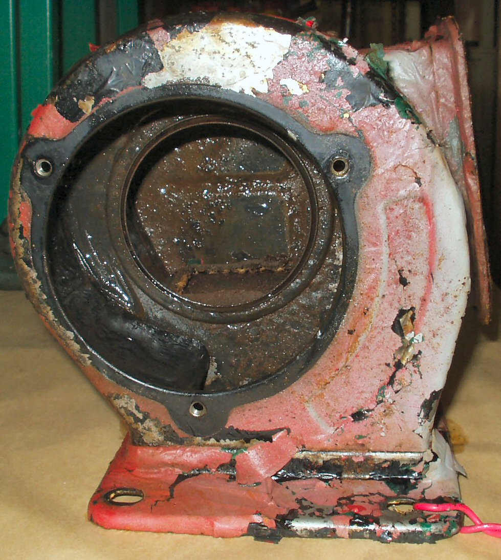
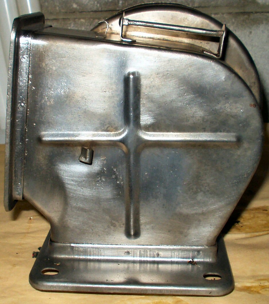
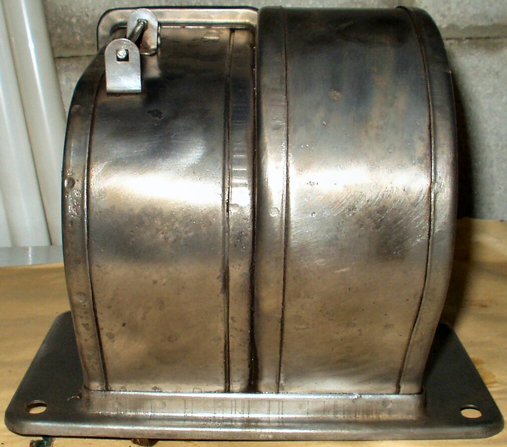
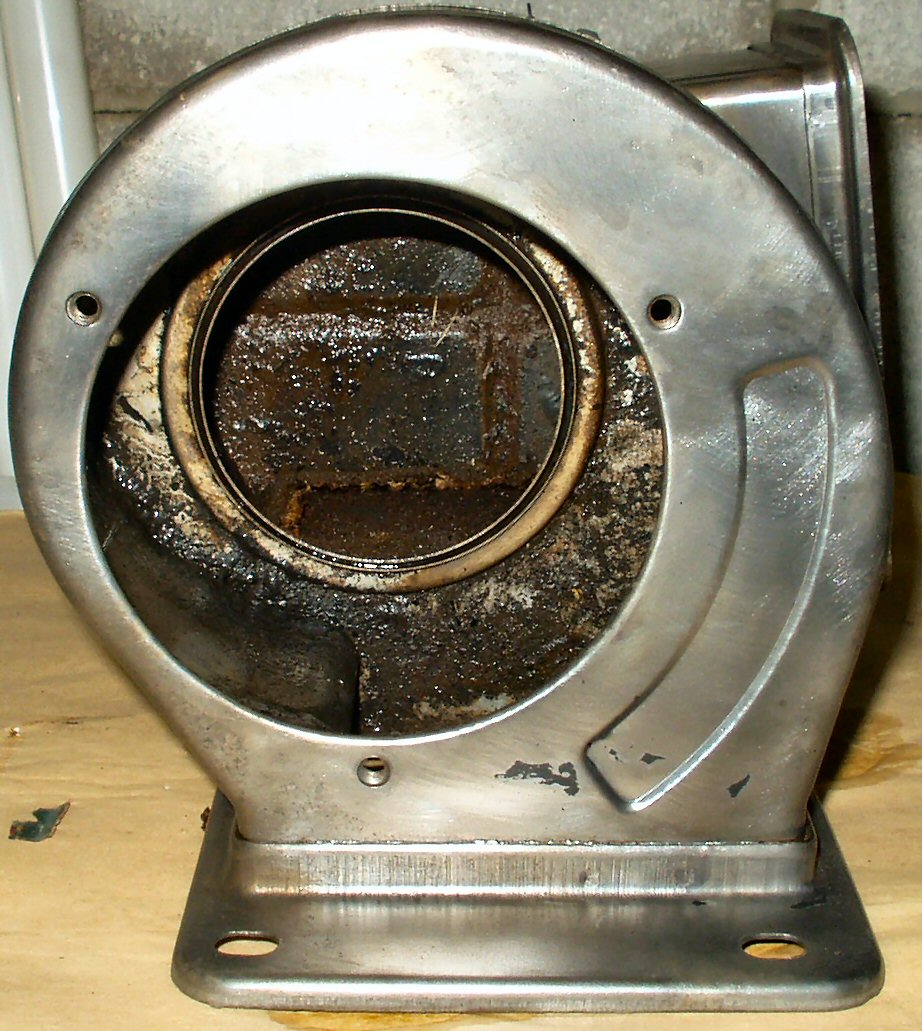
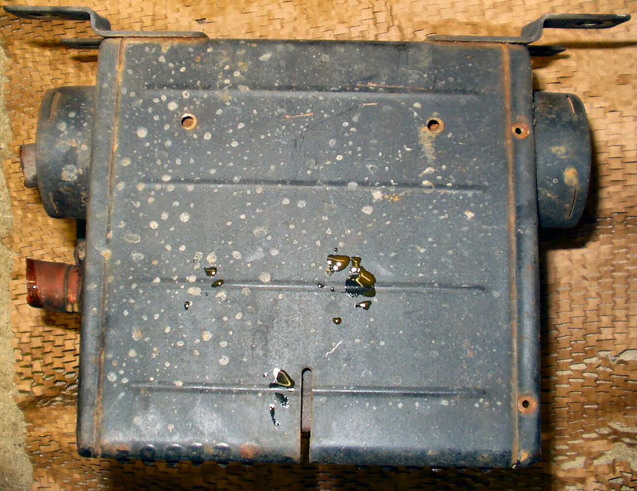
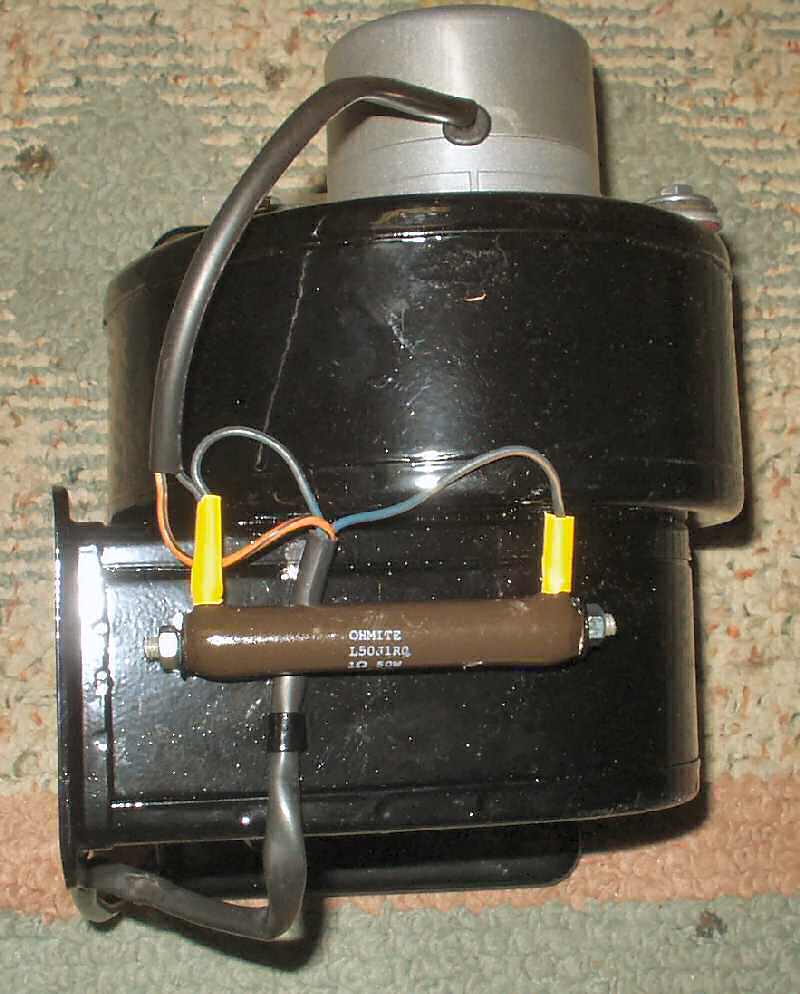
Fig. 4 The 'New' Blower |
Fig. 5 Bottom Shot |
When I got the heater it was exactly as pictured. It worked but was a bit rusty, very dirty, and as expected, the resistor was open. I started pulling it apart to de-rust it and rebuild it.
I put the main housing in the de-rust tank after removing all the rubber parts, and started taking the motor apart. The brushes looked OK, though the commutator was lightly scored. I'll add these parts to the de-rust tank later.
Fig. 6 De-Rusted 1 |
Fig. 7 De-Rusted 2 |
Fig. 8 OEM Sticker! |
Fig's 6,7,8 show the heater housing after 4 days of de-rusting. There were 3 layers of paint, the bottom one a gloss black. The top two bubbled right off but the OEM coat stuck in a couple of places. The last pic shows the OEM sticker someone had painted over.
Fig. 9 Same Housing? |
Fig. 10 Same Housing 2 |
Fig. 11 Inside Hard to Clean |
Fig. 12 No Screen |
Amazing what five minutes with a wire wheel on a drill can do to a part after it has gone through the de-rust tank! This is one piece that needs a sand blaster cabinet. The inside is very hard to clean with my current set up using wire wheels. I removed the two screws holding the flop door in place, and removed the door. It still had a piece of foam attached to it. I put the flop door in the de-rust tank overnight, then cleaned it up with the wire wheel. I sat it aside for later coating, and new foam. I ended up using the sand blaster to clean the inside prior to powder coating.
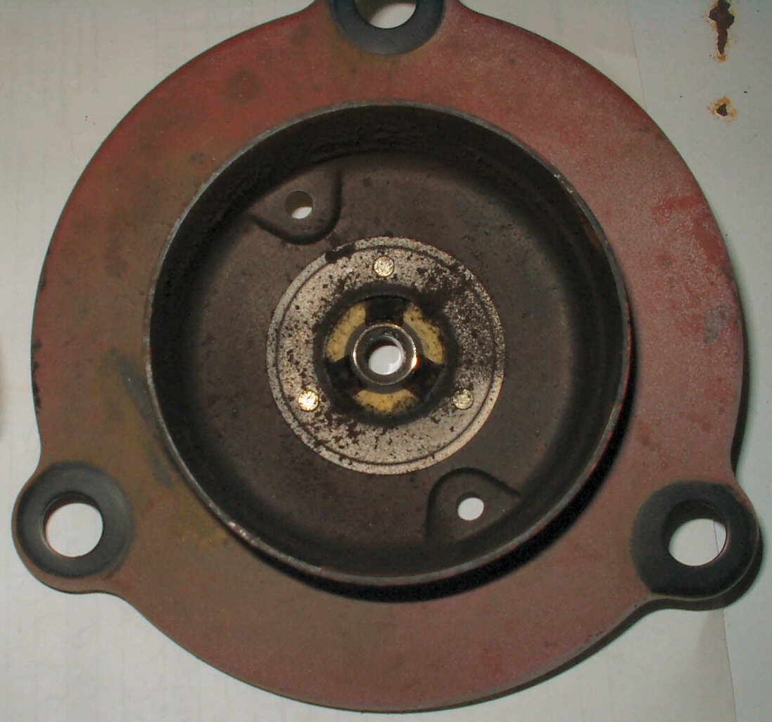
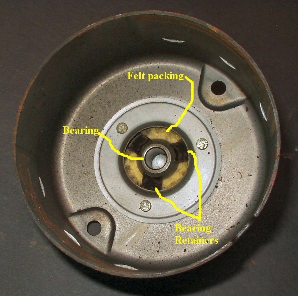
Fig. 13 Top Motor Cover/Bearing |
Now I could start on the motor housing. The bottom bearing looked OK, but the oil felt was dry. I pressed out the bearing with a screwdriver as I don't think putting it in the de-rust tank would do it any good! See Fig. 13. The plate was added to the de-rust tank.
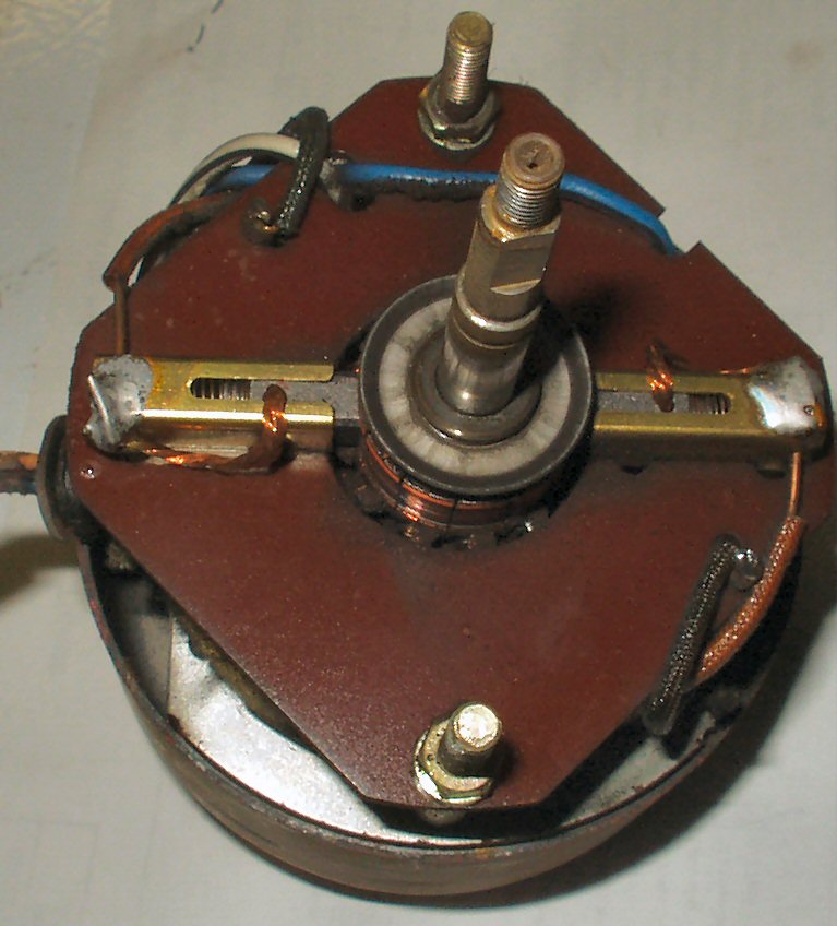
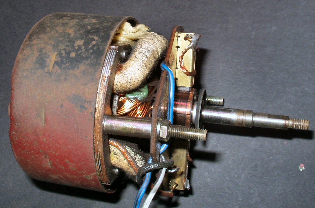
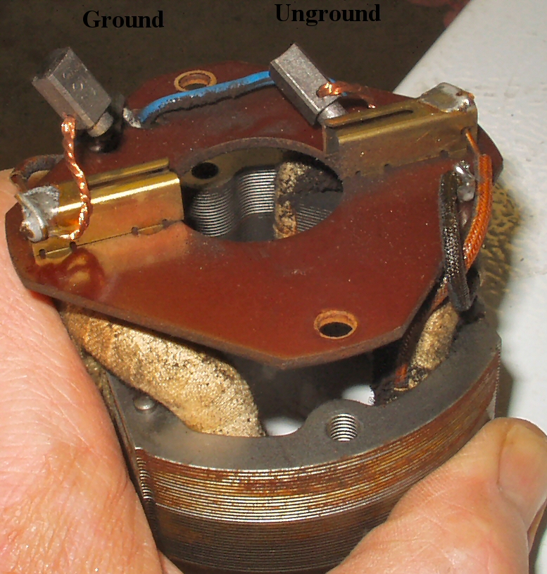
Fig. 14 Brushes/Motor |
Fig. 15 Bit of Scoring |
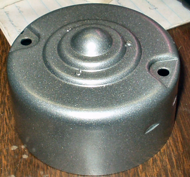
Fig. 16 Bottom Motor Housing |
Fig. 17 Bottom Outside |
The motor and brush assembly appeared clean, and the brushes still have 1/2 their length. However, the commutator was scored pretty deep, and needed attention. See Fig. 15. The motor housing was added to the de-rust tank after removing the bearing. Fig. 16 shows the bottom housing with parts labeled, and Fig. 17 shows the housing outside before putting in the tank.
Fig. 18 Armature in Chuck |
Next I started working on the brushes and commutator. When you take this apart, be aware of the small bearing shims on the motor shafts! They must go back in the same place in order to maintain the bearing end play! In order to get the scoring out of the commutator, I chucked the armature shaft into a drill that was clamped in a vice. See Fig. 18. I ran the drill at low RPM and used a commutator dressing stone to dress the scoring out. (You can also use fine 400 grit sand paper.) Be careful to keep the commutator moving at all times so you don't create flat spots on it! I followed this with some 1000 grit sand paper, and then blew out all the dust.
Now I could address the brushes themselves. I used a flap wheel on a Dremel tool to square up the brushes and remove all the scoring. Fig. 19 shows the left brush after dressing and the right brush to be done. Notice the right brush has a very concave face?
Fig. 19 Dressed Brush |
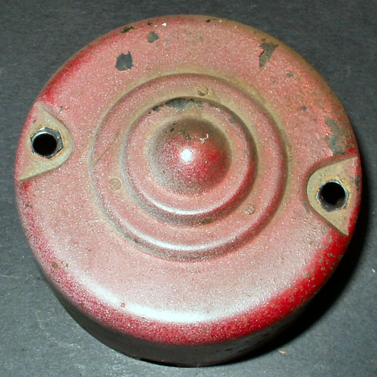
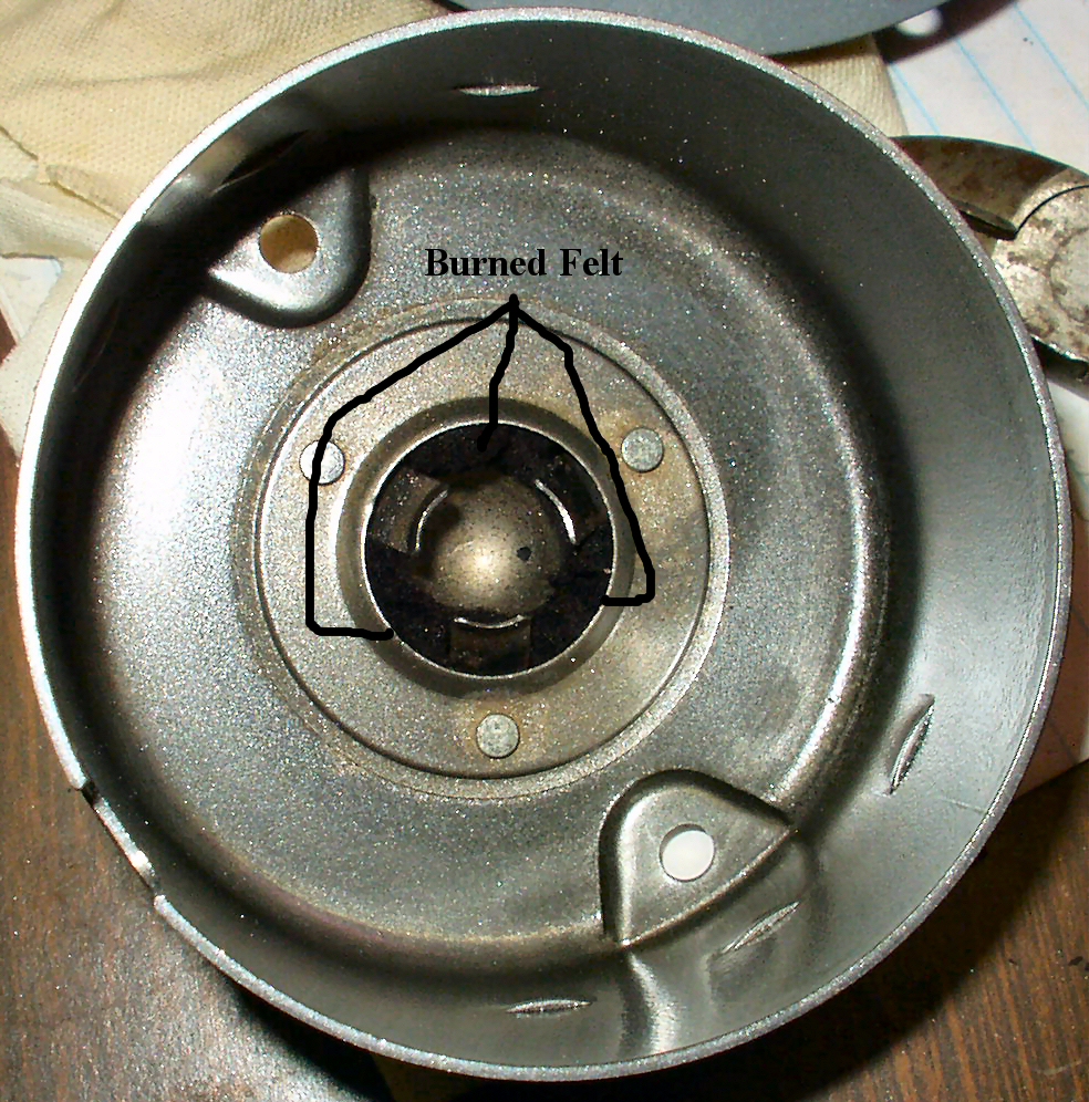
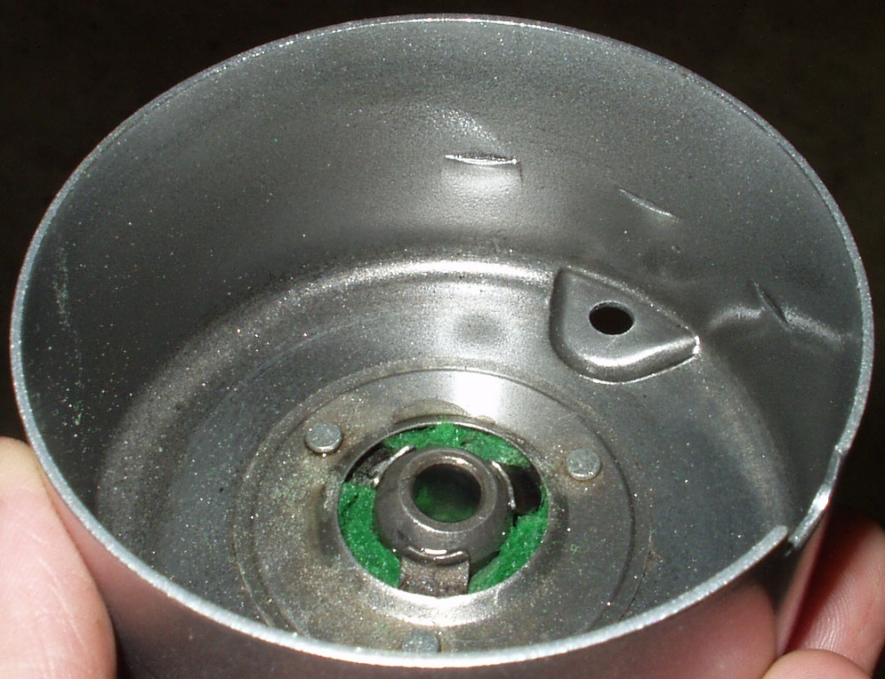
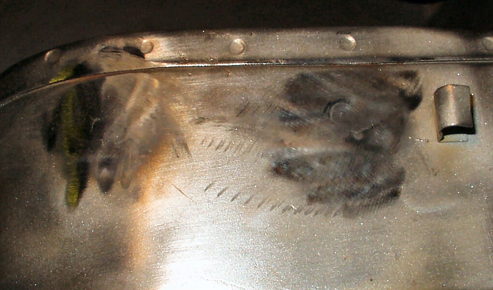
I set all the internal motor parts aside and tackled the motor end housings. They contained an oiling felt that looked to be made of white felt. I looked on the web and found references to felt being used as an insulation, and was supposedly good to 1000 degrees. So... I coated the smaller cap with StarDust Silver powder, and popped it in the oven at 400 degrees for 12 minutes. Fig. 20 shows the outside of the cap. Looks good right? Well, see Fig. 21 for what happened to the felt ... It just turned to ash. I guess this was cotton felt, not fiberglass felt? I removed all I could get, blew it out, then considered drilling out the rivets and taking it apart to replace the felt. After realizing that the rivets also held the bearing retainers in place I decided to just replace the felt without that step. I found some green 'pool table' felt at a craft store and using a large washer as a template I cut out two pieces and worked them in under the bearing retainer clips. Then I used the smaller scrap pieces, and worked them into the spaces in between. Next I applied 30 weight motor oil. For those that may not know, the felt holds a lot of oil and through wicking (capillary action), it keeps the bearing lubricated for a LONG time. See Fig. 22.
Fig. 20 Cover Powder Coated |
Fig. 21 Burned Felt |
Fig. 22 New Felt |
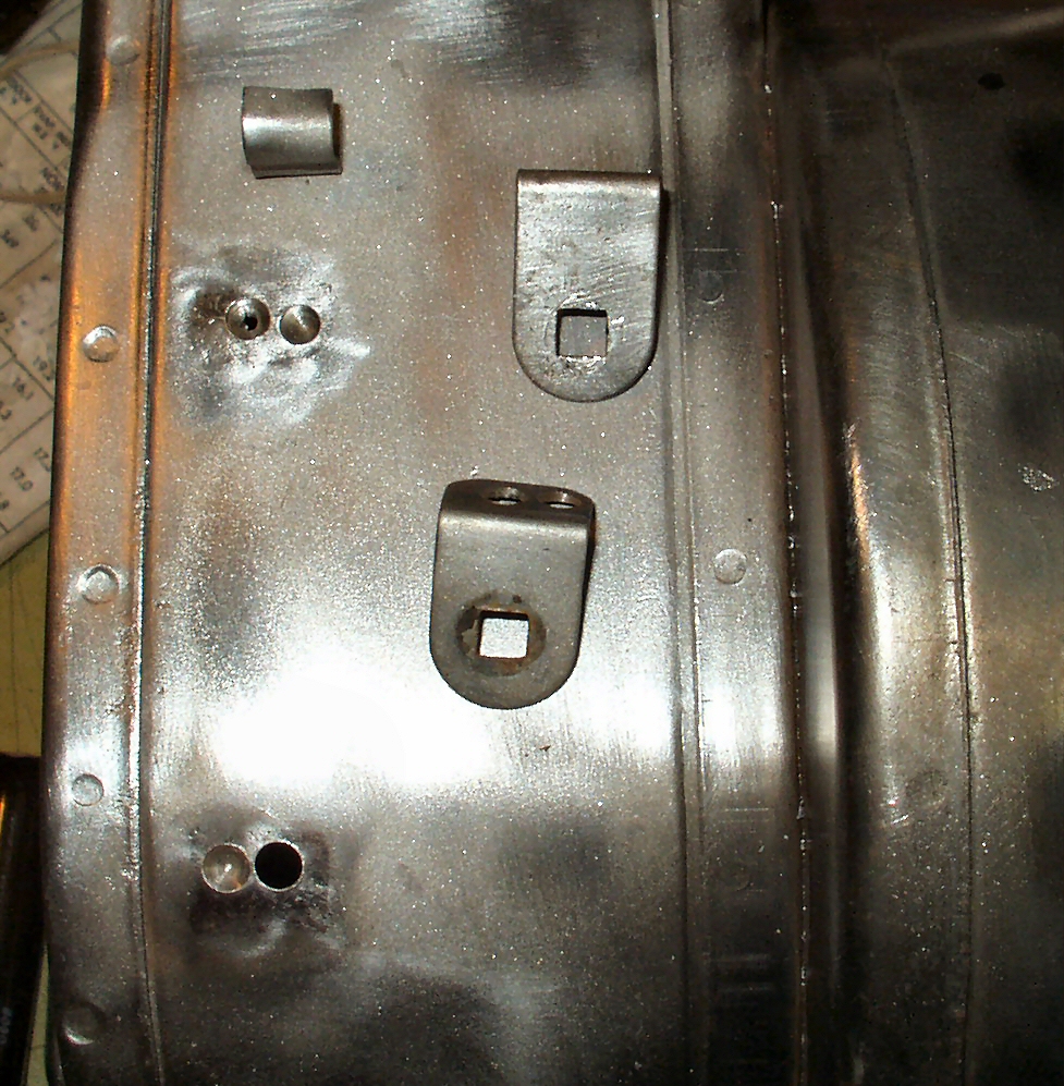
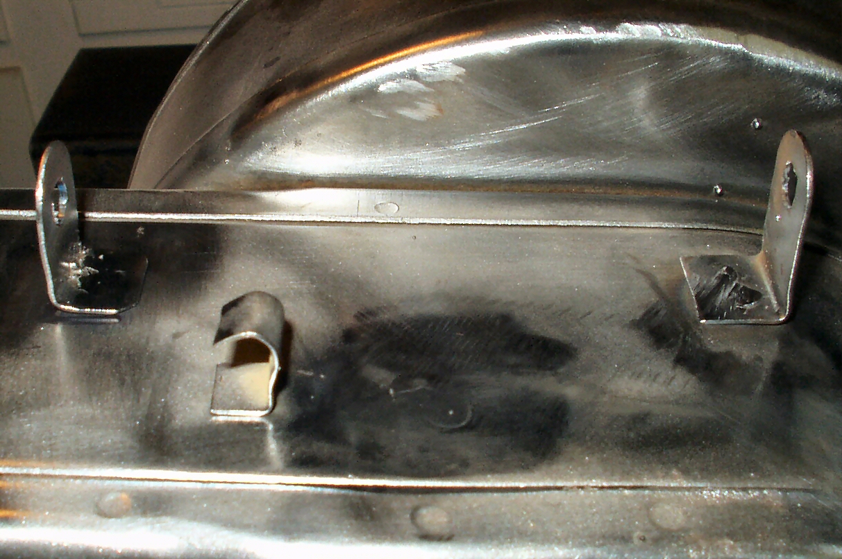
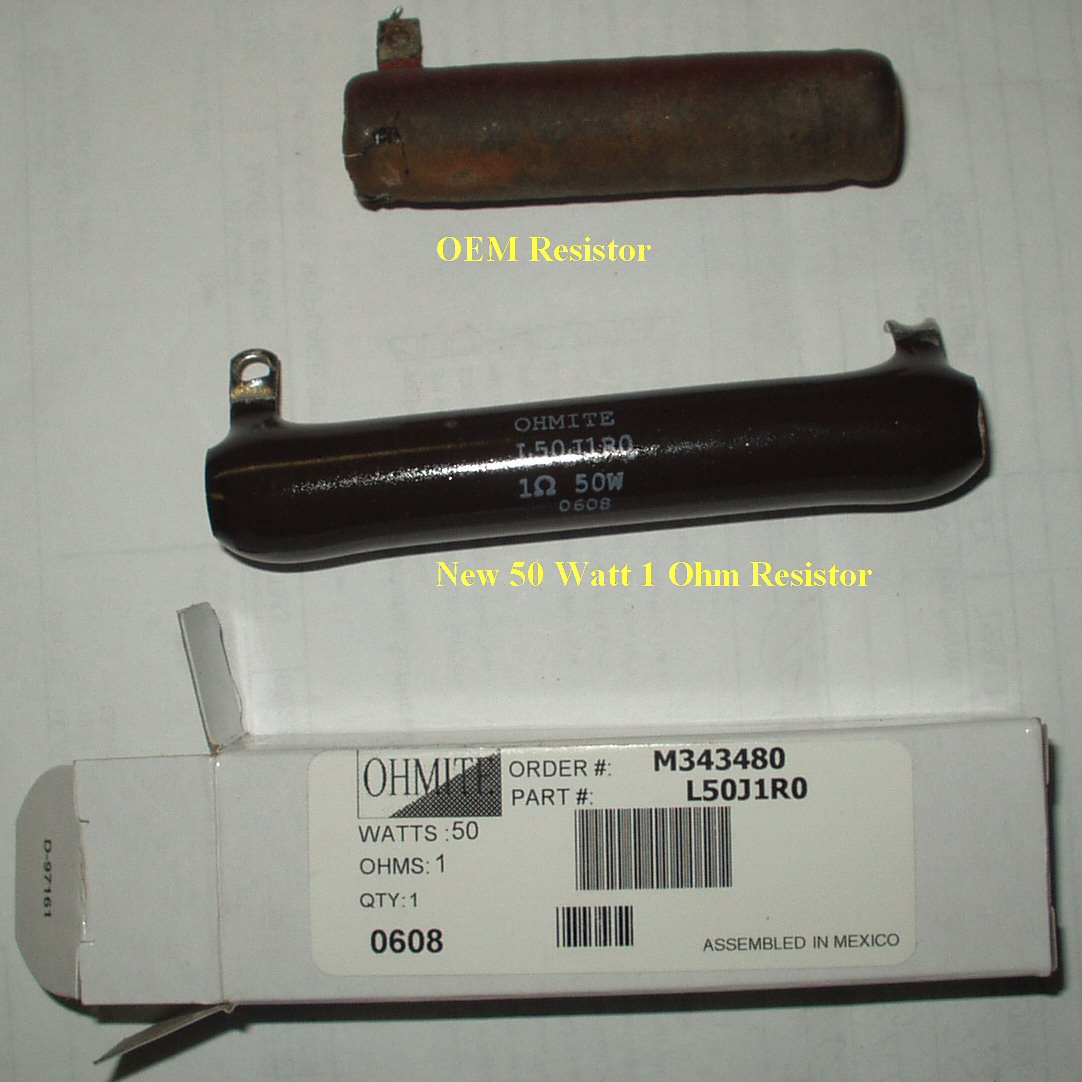
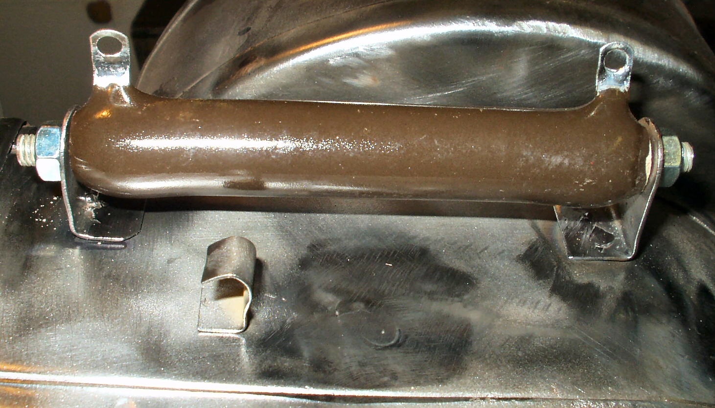
Since the next part to be powder coated was the main housing, I had to fix one thing that was bugging me about it. The OEM resistor for low speed is no longer available, and the replacement resistors available from Mouser and other places are a tad longer, and won't fit into the factory brackets. I decided to fix this problem. First I drilled out the spot welds holding the OEM brackets. See Fig. 23. I then welded up the olds holes Fig. 24, moved the brackets back, and to the left, Fig. 25 then welded them in their new location. Fig. 26 shows the new resistor I got from Allied Electronics. Ohmite Part# L50J1RO It 's a 1 ohm, 50 watt resistor. Fig. 27 shows it mounted in place.
Fig. 23 Old Removed |
Fig. 24 Holes welded up |
Fig. 25 New Location |
Fig. 26 New Resistor |
Fig. 27 New Resistor in new place
|
I decided to coat the main blower housing gloss black. This piece was a pain in the ass to get coated properly! There are so many angles, and interior places to coat that I had to do it twice to get it halfway right. Anyway Fig. 28 shows the final results of all the hard work.
Fig. 28
All Done and assembled
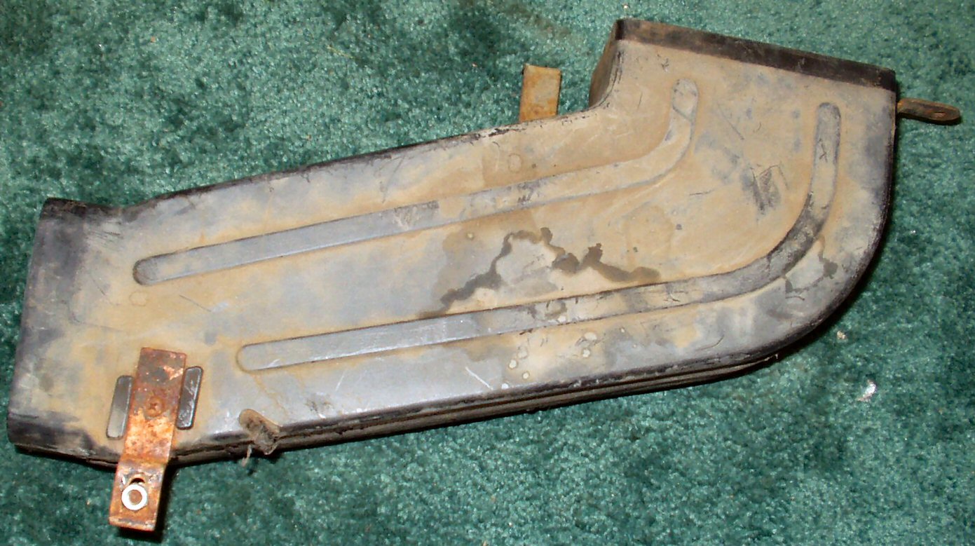
Fig. 29 Duct Top |
Fig. 30 Duct Bottom |
Fig. 31 Plastic Paint |
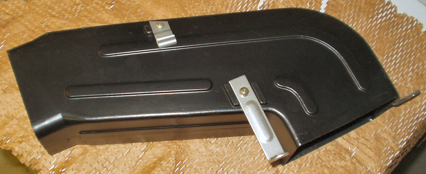
Fig. 32 All Cleaned and Painted |
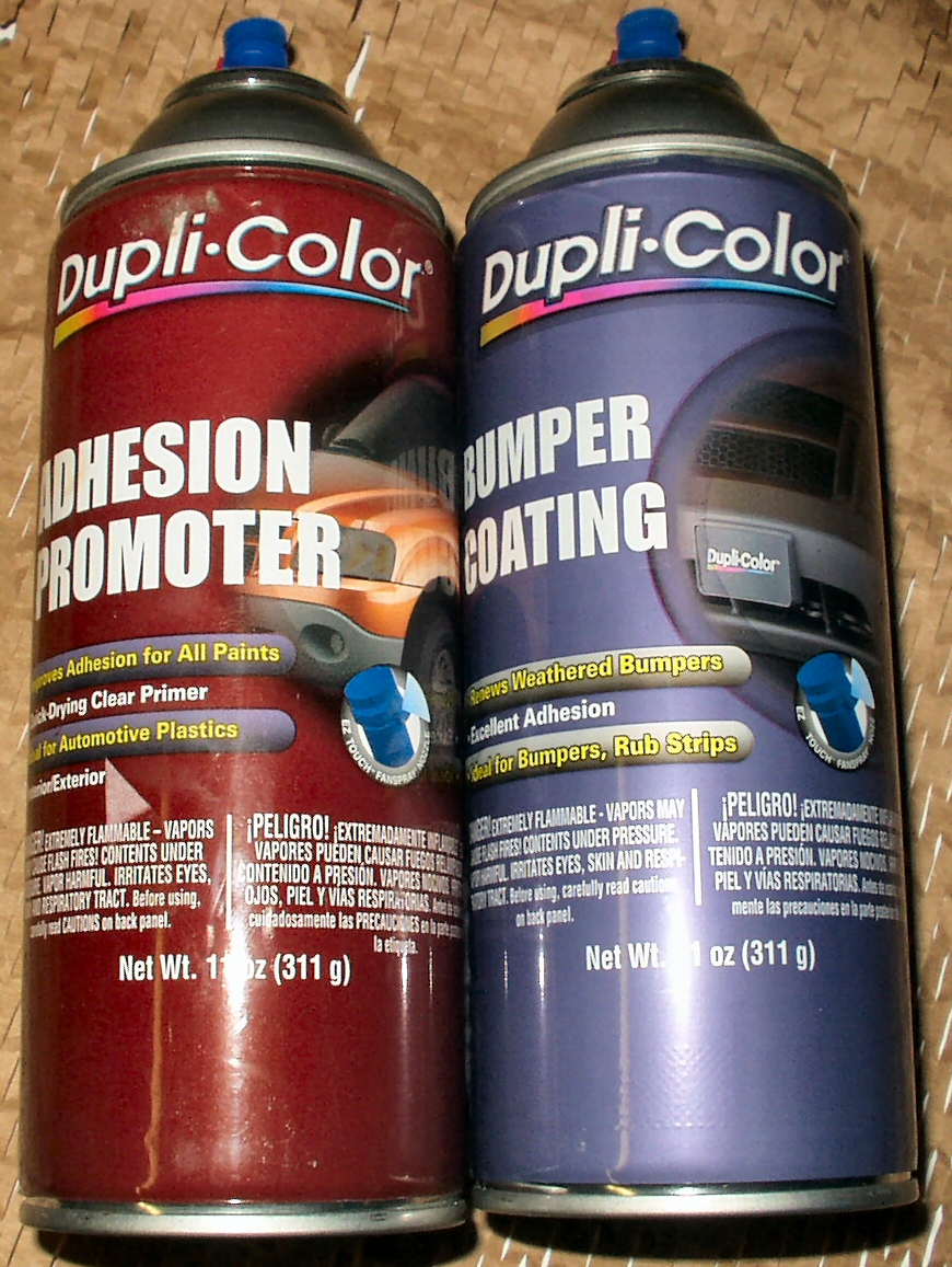
The next piece I scored on E-Bay, was the front heater duct. As you can see from the above pics (Fig. 29-30), it was dirty, the brackets were rusted, and someone had cut it with a saw at some point it it's life. I removed all the brackets, placed them in the de-rust tank, then cleaned the housing. Next I used some JB Weld to repair the cut place in the housing. After sanding that down I sanded the whole thing just to rough it up a bit then applied two coats of clear Dupli-Color Adhesion Promoter then three coats of black Dupli-Color Bumper/Trim paint. It came out looking brand new! After de-rusting the brackets, I powder coated them with StarDust Silver and reattached them. Big difference between Fig. 30 and 32!
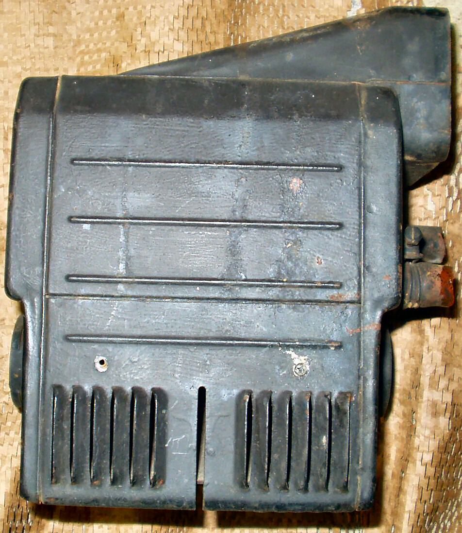
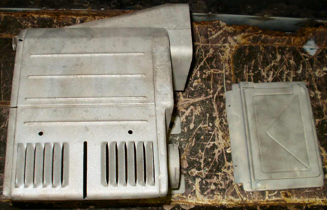
I finally acquired a front heater box! I went to a TLCA club meeting 8/27/2006, and Jamie, one of our members, had a box out of a 1974. I have determined that it is actually a 73. Here are some before shots of it.
Fig. 33 Front |
Fig. 34 Right Side |
Fig. 35 Back Side |
Fig. 36 Left Side |
Fig. 37 Top Side |
Fig. 38 Bottom Side |
Before
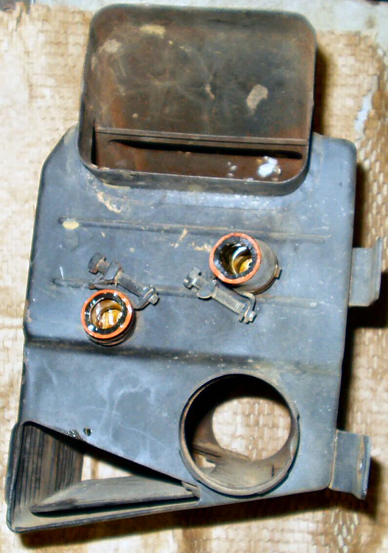
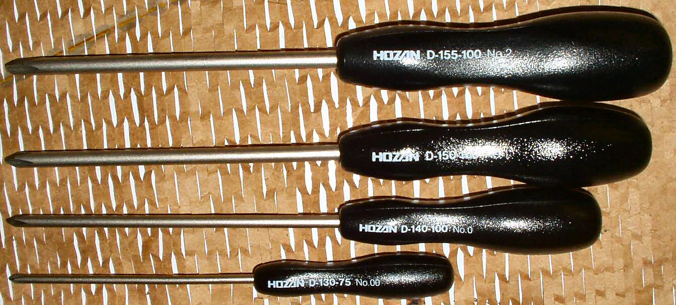
It is missing some screws, the flap is frozen with rust, the foam seal is gone, and the knob is missing for the defrost. I have ordered a kit to replace the foam and screws from aatlas1x@aol.com. I also got the OEM replica stickers from him. See pic of rebuild kit below...
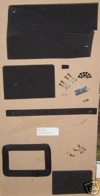
Fig. 39 JIS Screwdrivers |
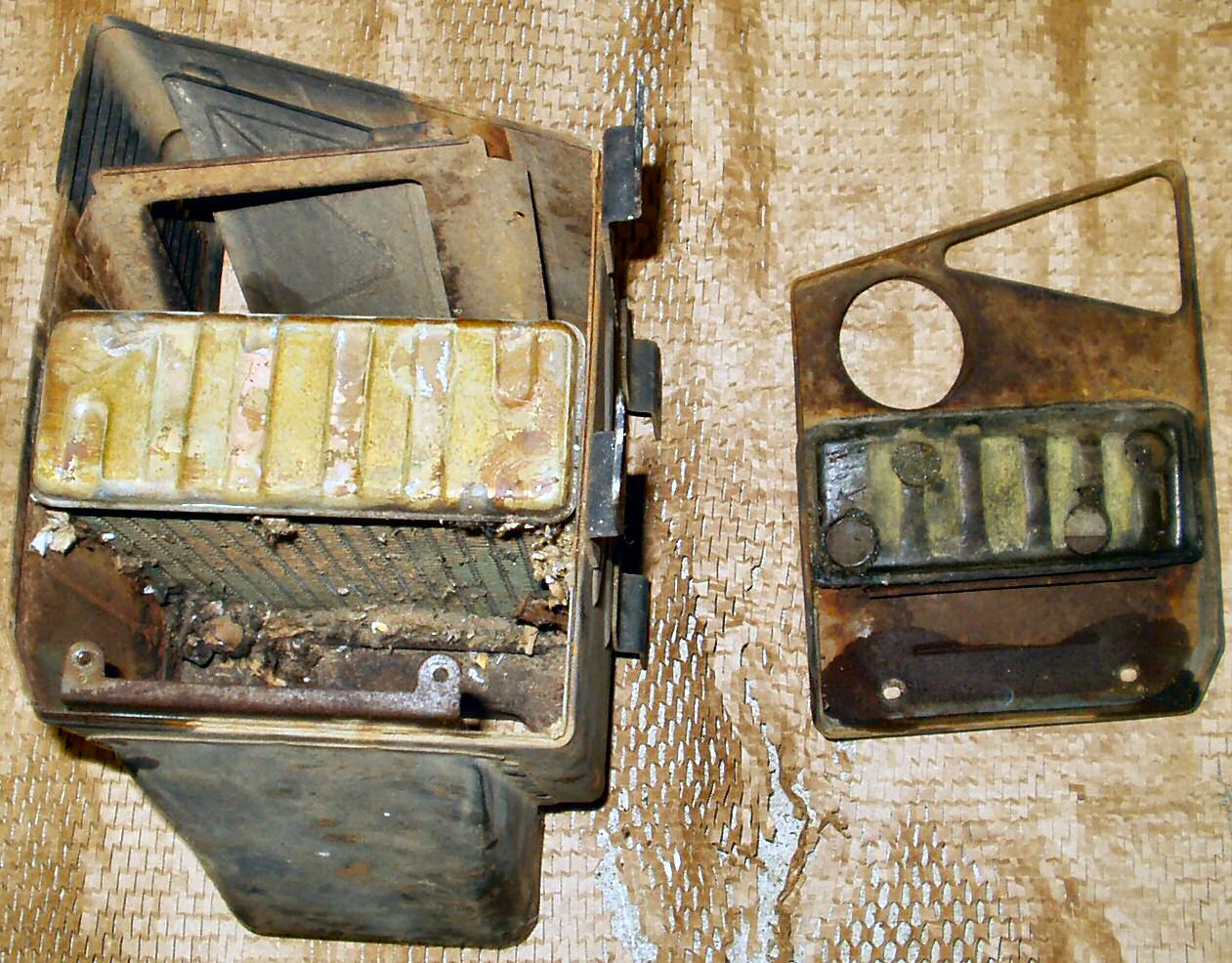
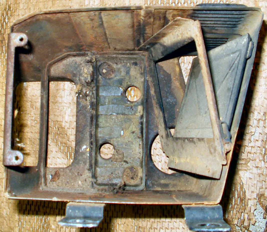
Fig. 40 Left Side Off |
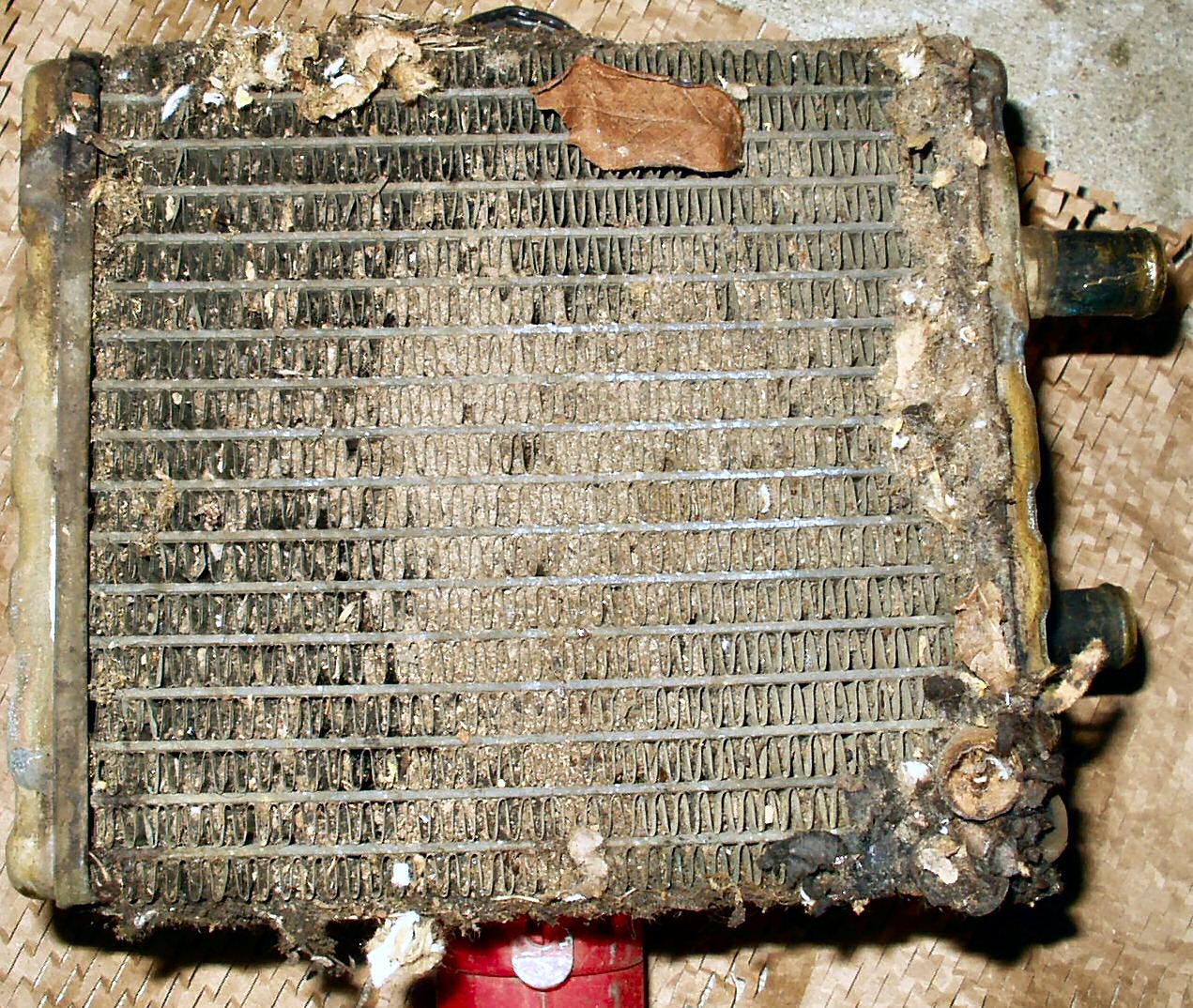
Fig. 41 Core out |
Fig. 42 Pheeeeuuuuwwww! |
At this point, I put all the pieces into the de-rust tank and started cleaning the heater core. First I sprayed water through the back to dislodge the majority of the crud, then sprayed it down with a detergent solution, and let it soak for a while. More water through the back then a soft bristled brush to remove more stuff. Repeat till satisfied! Once I had it mostly clean I put on my gloves and mixed up a solution of Muriatic Acid and water. I used a funnel and filled the heater core with this solution, and let it soak for several hours. A LOT of hardened crud came out when I poured the solution out. I poured the acid from the core through a coffee filter so I could reuse it. I flushed the core out several times with the solution until stuff quit coming out then flushed it thoroughly with water. I used my compressor to pressure test it to 15 psi and found no leaks. See Fig. 43 for the cleaned heater core. Now you can see the light shining through!
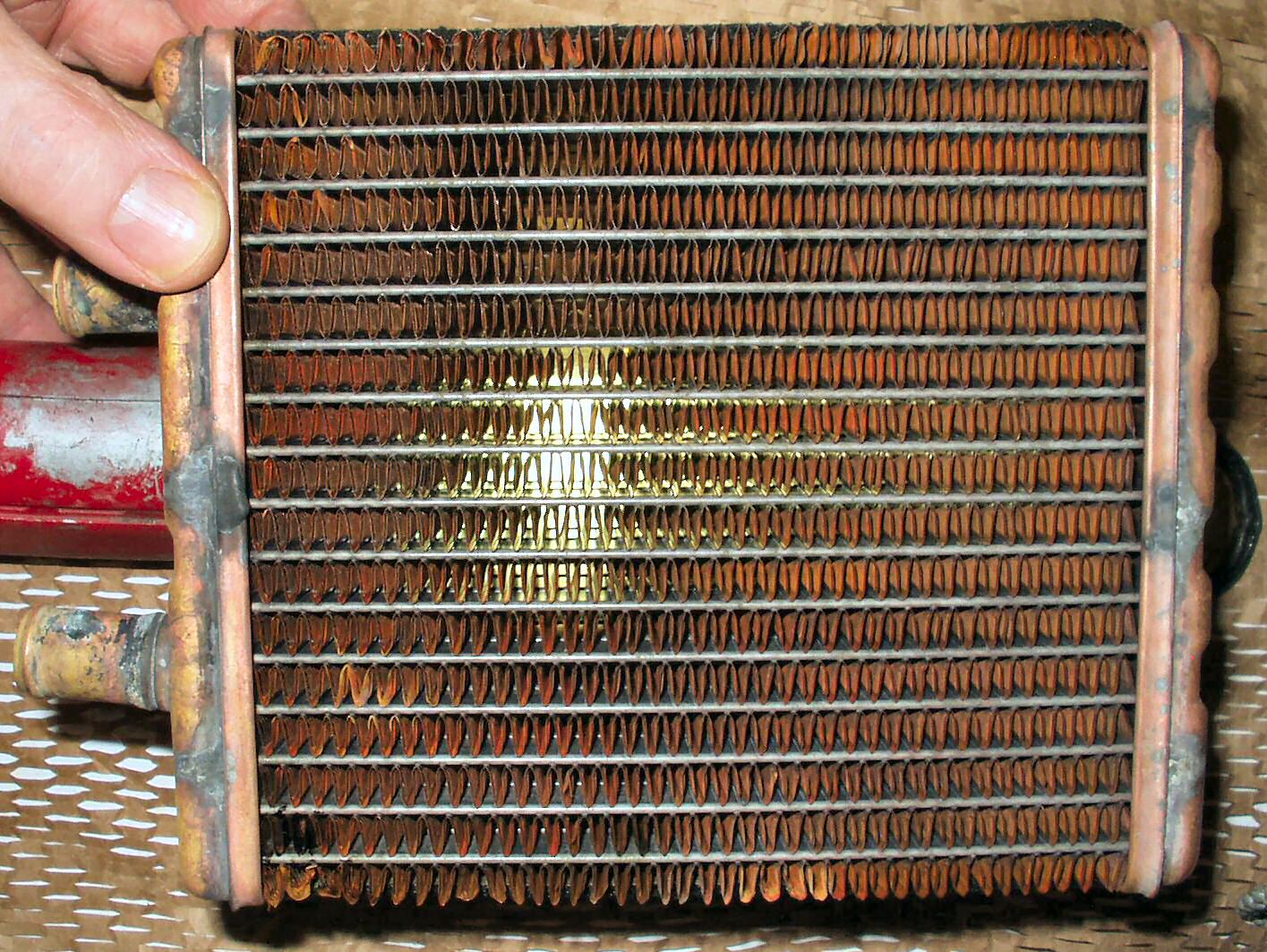
Fig. 43
Cleaned Heater Core
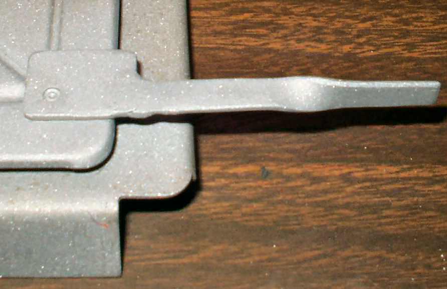
Fig. 44 Missing Lever |
Fig. 45 Fabbed Piece |
Fig. 46 Welded, ground, blasted |
Now the observant among you may have noticed the missing lever in Fig. 36 & 44? Well I looked on the web, and found some pics of what it was supposed to look like and made one from 16ga. See Fig. 45. It took three attempts to get the settings correct on the welder! Anyway it turned out well. See Fig. 46. Anybody have a heater knob they want to part with?
Fig. 44 Cleaned Blasted |
Fig. 45 Ready for Oven |
Fig. 46 Nice! |
Fig. 47
|
Fig. 48
|
Fig. 49
|
OK, now that the parts were de-rusted, I took a drill mounted wire brush and tried to remove the remaining crud. That did not work so I put it in the sand blaster that I recently acquired. That did the trick! See Fig. 44.
I wiped all surfaces down with acetone and powder coated the entire box assembly with Star Dust Silver powder. See Fig. 45-46.
I replaced all the screws with the ones I got in the rebuild kit, then replaced the defroster divert door foam. Last I put on the sticker I got from AATALS1X. See Fig. 47-49.
Hosted by Global Software, Inc.
©1998 - 2023 Mark C. Baker Web Designer
Please: No part of this web site may be used without express permission... email mbaker@globalsoftware-inc.com for permission.