So what is it about the cowl vent that is such a mystery? Well
a lot of folks have it, but don't know what it does, or they have it, and
it doesn't
work, or they have it, and all it provides is a religious experience for
the feet... so they close it off...
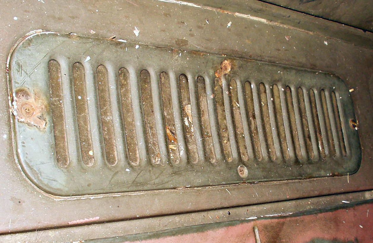
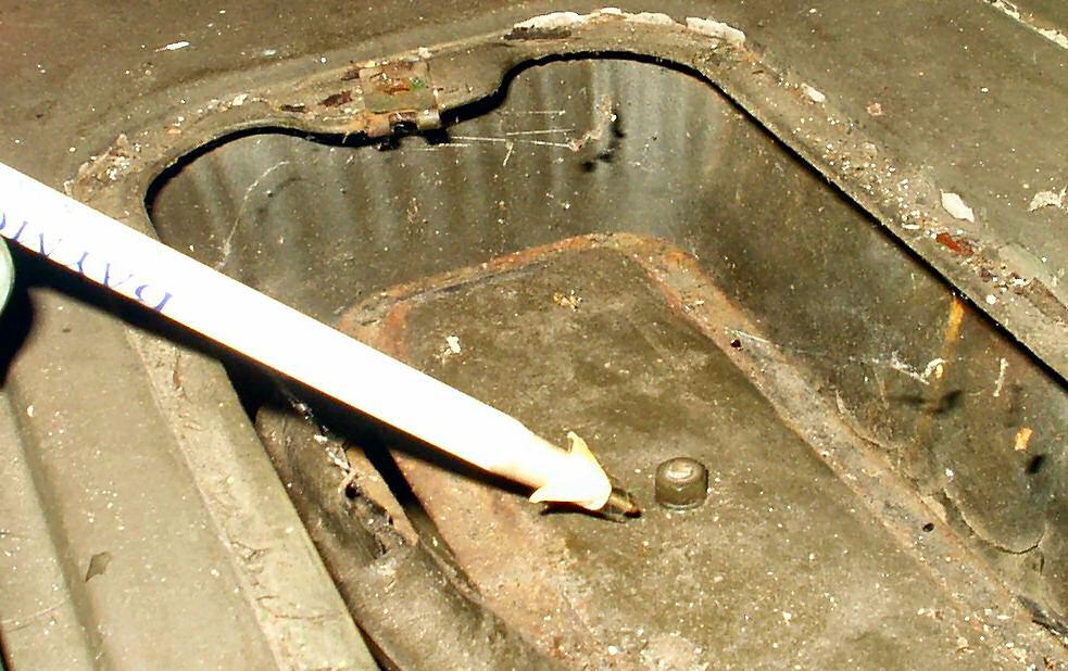
Fig. 1
Cowl Vent
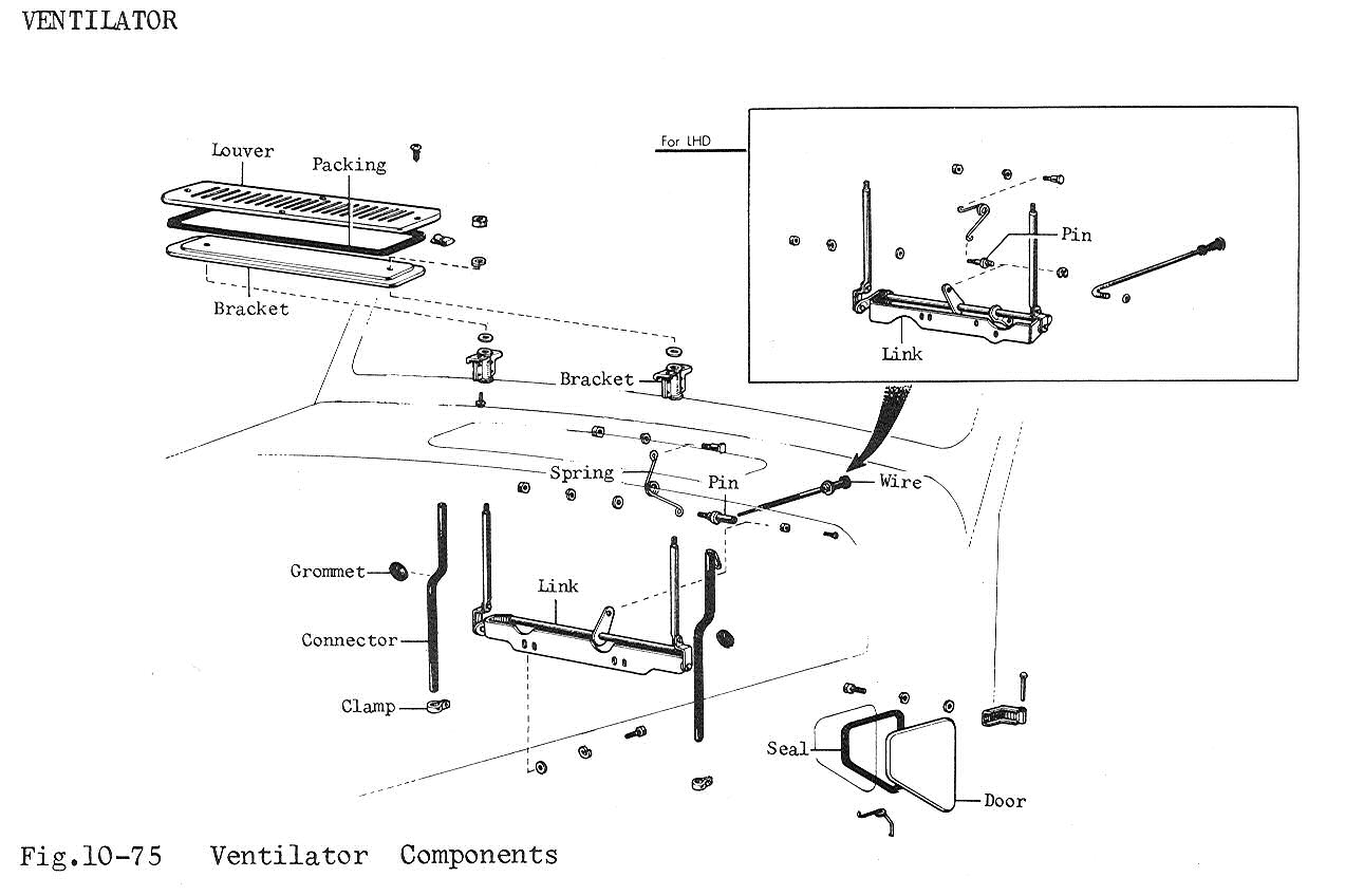
Fig. 2
FSM Diagram
The cowl vent functions to allow fresh air into the cab while
supposedly not allowing in water. The design works well unless the drain hoses
clog or the pop-up vent gasket fails. Both of these had occurred on mine! See
Fig. 2 for the FSM diagram.
Removing the Cowl Vent
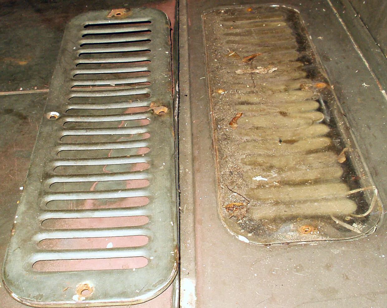
Fig. 3
Remove Cover
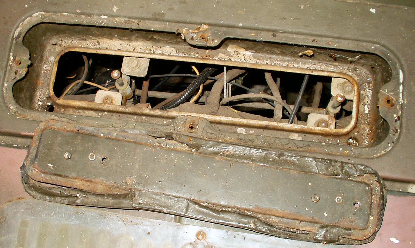
Fig. 4
The 'Pop-up' Vent
Fig. 5
Remove two nuts
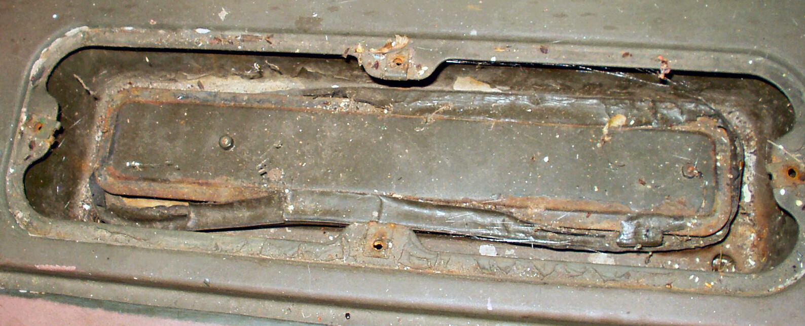
Fig. 6
Fig. 7
Rotted Gasket
To open the vent for inspection, remove the 4 screws shown
in
Fig. 3. You may find a plastic or metal cover
under the louvered cover. MAF and others sell these to block the vent off
in winter,
or permanently if your hoses are rotted, and you are tired of the feet washing.
Remove this cover, and you will see the pop-up vent as shown in Fig.
4. The vent is held on with two 7mm hex nuts. Remove these carefully!
Apply some PB Blaster or something. If you break these off you will have
to
replace the entire assembly or weld on a threaded rod! Fig.
6 shows the now exposed mechanism that raises and lowers the pop-up
vent.
Fig. 7 shows the rotted gasket on mine. This will
have to be replaced or fabricated. SOR wants $56.00 for this!
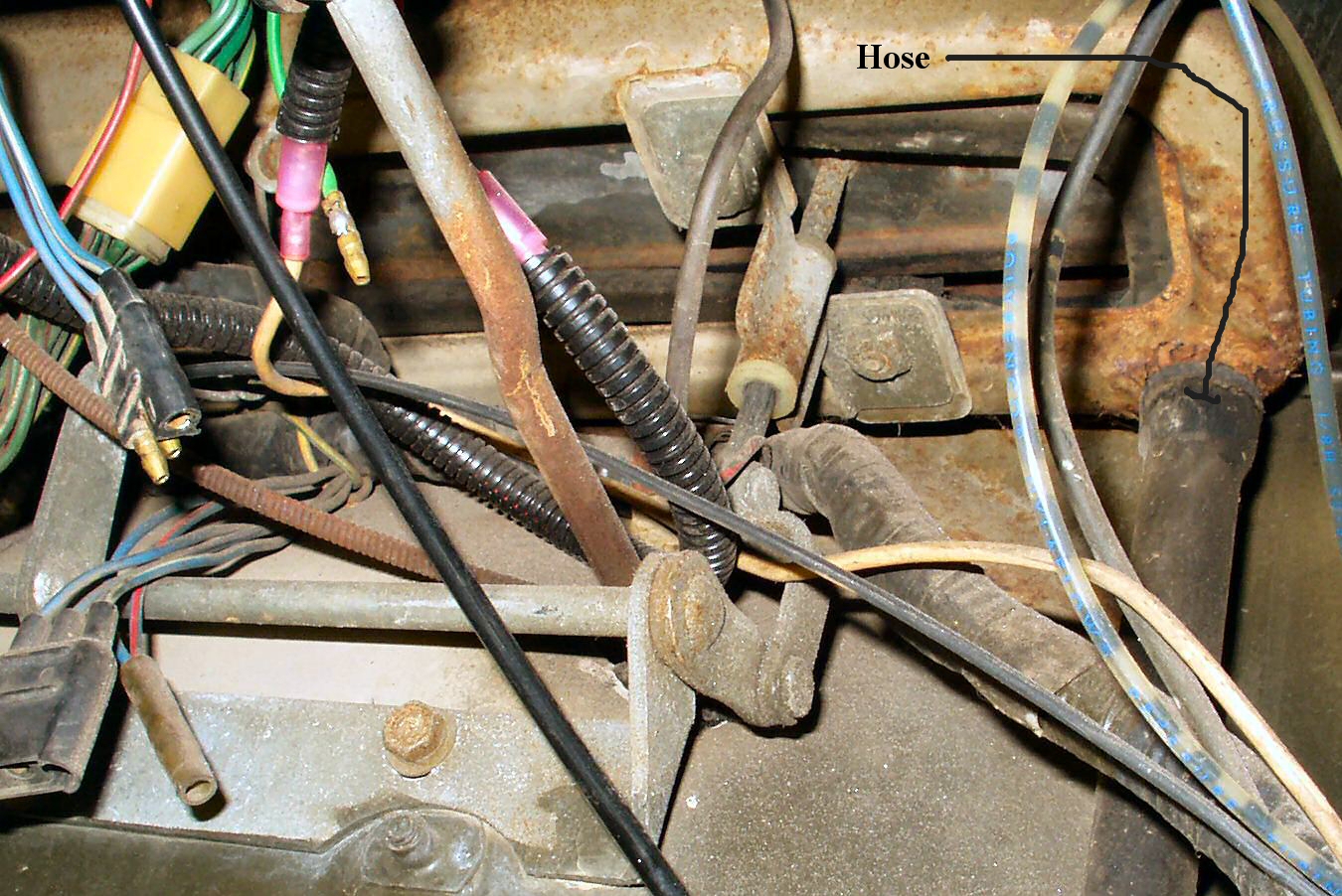
Fig. 8
Rotted Hoses
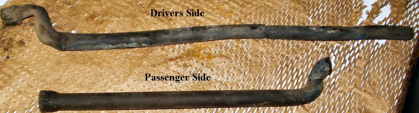
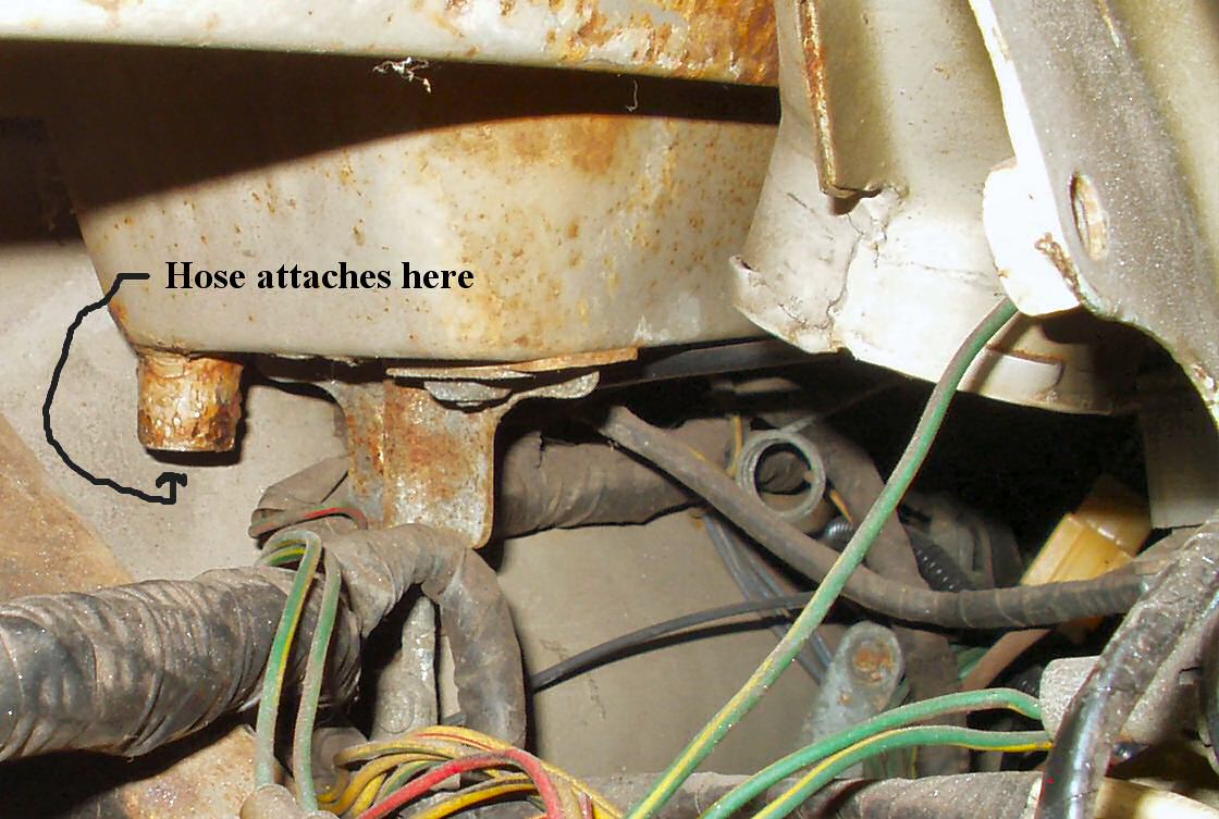
Fig. 9
Drivers Side Attachment
Fig. 10
Pass.Side Attachment
My vent, though stiff, mechanically works, but
the hoses are shot allowing water in. See Fig. 8.
Fig. 9-10
show where the hoses attach to the bottom of the vent housing. You will need
to remove the heater box to make access easier to this area. Since I am in the
middle of replacing the home built unit the PO put in I already have it out.
Removing the Lever Assembly
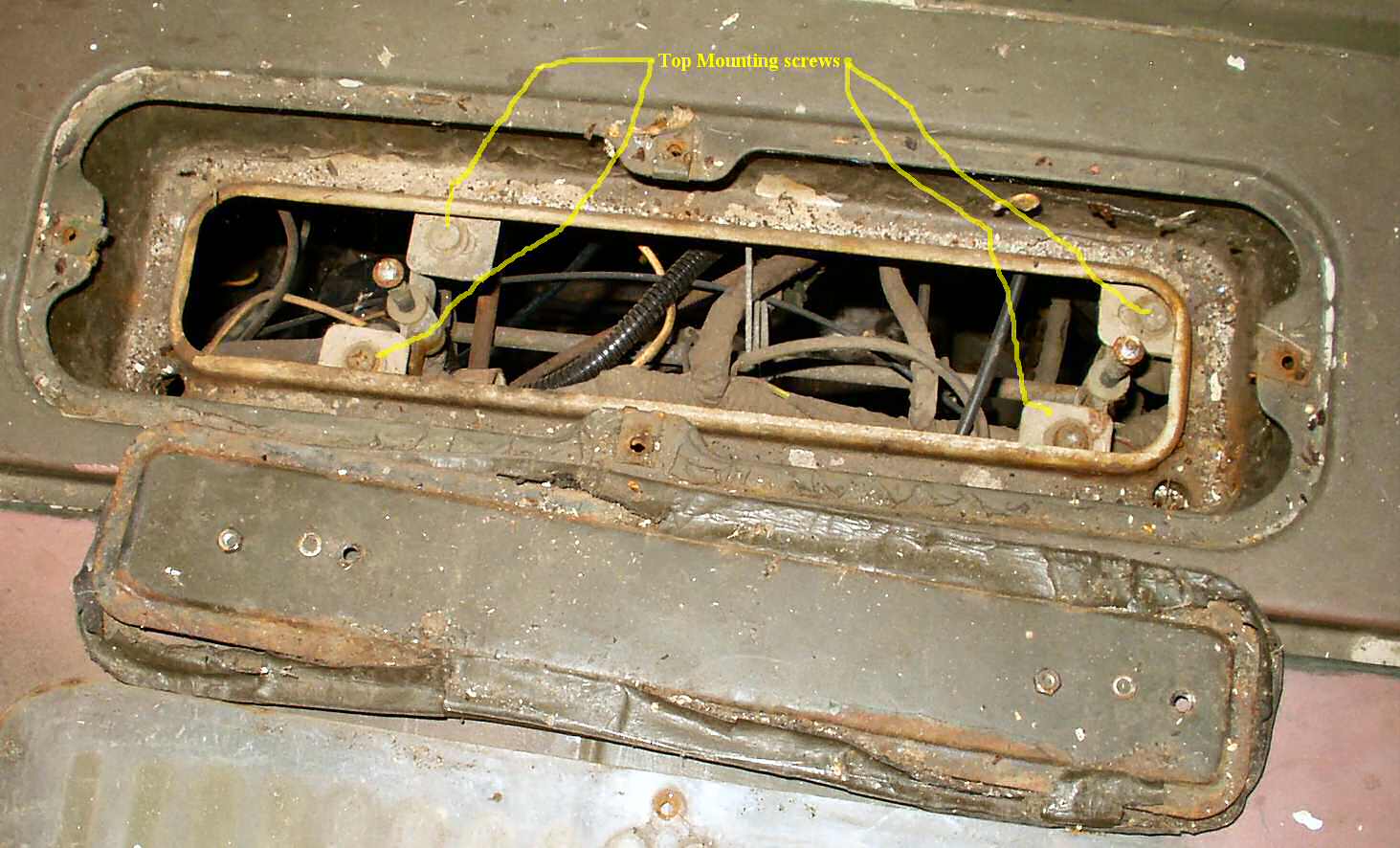
Fig. 11
Removing Top Bolts
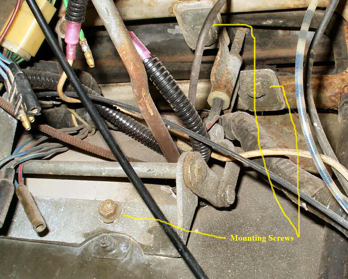
Fig.12
Removing Lever Bracket Bolts
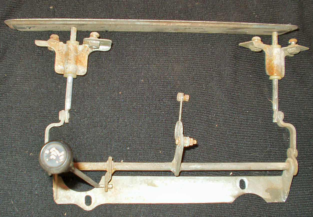
Fig. 13
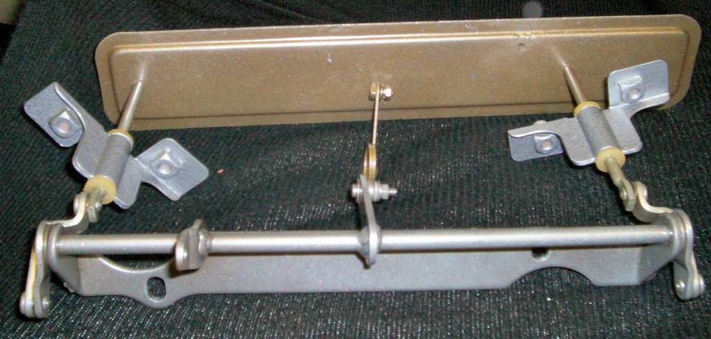
Complete Removed Assembly
Fig. 14
Powder Coated and ready to install!
Use the FSM diagram in Fig.
2 to remove all the bolts that hold the assembly in place. There
are two fire wall bolts, 4 lift anchor screws on top, the spring bolt,
and the lever
mechanism. See Fig. 11-13.
After removing this, I put the whole thing into
the de-rust tank, then sand blasted it, and powder coated it StarDust Silver.
Be aware
that the lift anchors have nylon bushings which I was unable to figure out
how to remove. Since I could not bake them to powder coat I just painted
them with
Rustoleum Hammered Silver. Came out looking great! See Fig.
14.
The gasket is no longer available so I will have
to make my own when I re-install this. When I get to that point I will update
this page again.