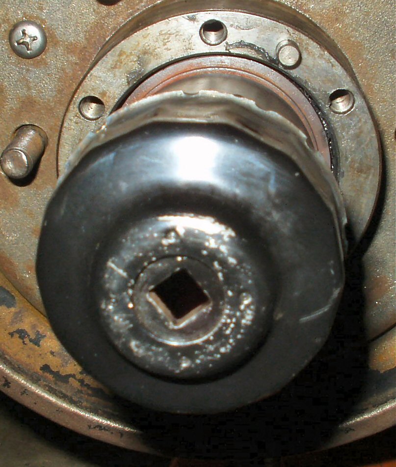
When I was researching the knuckle
rebuild, I came across several references to the size socket needed to remove,
and replace the axle hub retaining nut. What was confusing was, they all said if it was
a 1976 FJ40, or newer, or a mini-truck, the size was 54mm and anything older used
a 52mm. This agreed with my friend Cliff's axle hub nuts, which were from a mini-truck,
they measured 54mm. OK, well when I measured my 2/1971, AND an axle nut from a
1974 spindle, they measured 50mm! So off to Sears to buy a $22 2" socket.
When I got around to actually doing the knuckle rebuild, the socket would not fit! It was not deep enough! So after searching around for someone
who sold a 2" hub socket, and not finding any reasonably priced ones, I took
the advice from a LCML member, and made my own.
I started by trying to find a piece
of exhaust pipe I KNEW I had left over from my exhaust project on my Pathfinder. Hmmmm...
I must have gotten too zealous in my fall garage cleaning, and pitched
it. However, I did have a weird piece of thick walled steel pipe that was
2" inside diameter.
My first challenge was to figure out a way to turn
it with the torque wrench. My first thought was to use an old 1/2" drive
socket and weld it in place. Problem was, I did not have a large enough socket I was willing to sacrifice, and did
not feel like 'padding' the sides. Next I was going to try cutting a 1/2"
square hole in a piece of 1/8" plate, but did not want to spend 3 hours
with a file making it square. I was going through my junk box of steel, when
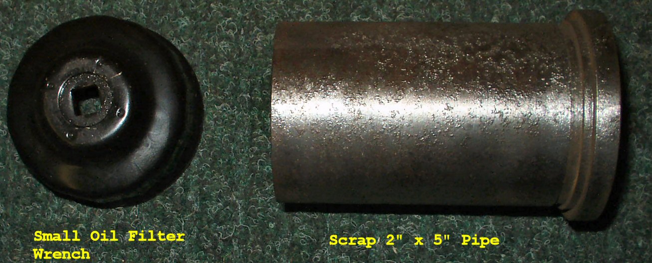
I found an old oil filter wrench with a built in 3/8" drive hole.
It looked about 2 1/4" in diameter! Sure enough, it fit the pipe perfectly!
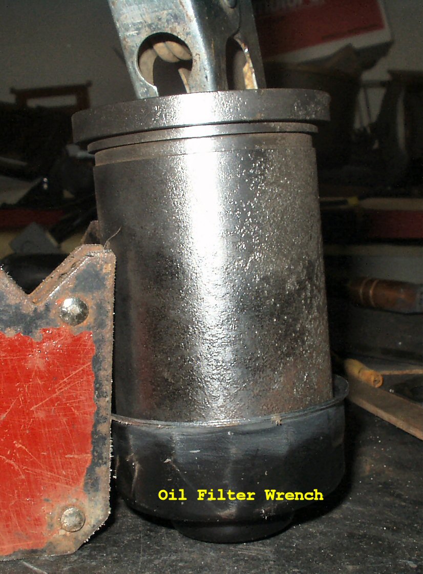
A few tack welds, and it was attached. See Figs. 1-2 .
Fig. 1
Scrap Parts
Fig. 2
Tacking cap to pipe
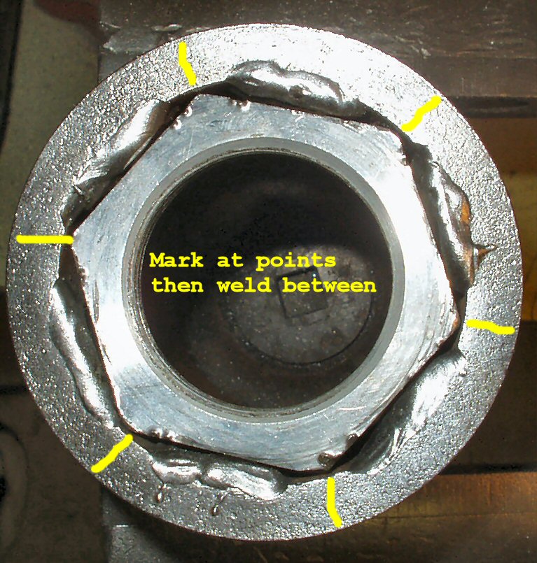
Fig. 3
Marking Pipe for welding
Fig. 4
Welding it
Fig. 5
Using it
My home made axle nut socket
OK, so now I have a way to turn it, how do I make a round thick
wall piece of steel pipe fit a hexagon shaped hub nut? I thought of cutting slots
in the pipe, and hammering it around a nut, but the walls were too thick to easily
cut. (No torch or plasma cutter)
As I was holding the nut inside the pipe, I
had a vision of that socket set they advertised a while back that claimed no
more rounded off nuts due to the fact these sockets gripped the nut on
the flats, not the edges. It suddenly dawned on me; the only thing I needed
to do was fill in the spaces between the 'corners' with weld, then file
them flat! (Note: Thanks to Herb Peyerl for pointing out
that these are called Flank Drive Sockets. They are patented by Snap-On Tools)
I started by holding the nut inside
the pipe, and using a black permanent marker to mark the corners. See Fig.
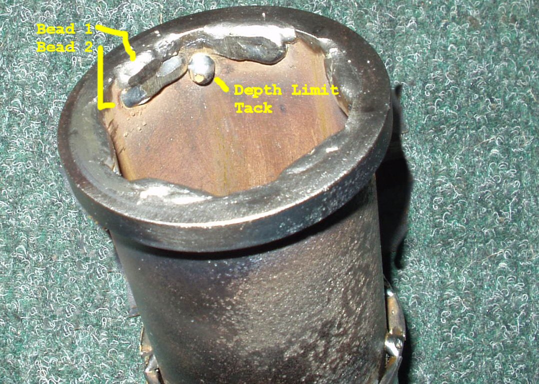
3. Next I ran some thick beads right on the outside edge between these
marks. After filing them down, and test fitting, I realized I needed more depth. So I added a second set of beads below the first. More filing, and fitting. It worked, but
I now saw the need to add a 'depth stop' to keep the socket from going too deep into the hub, resulting in the nut no longer being on the flat beads. I added
two tack welds almost even with the lower second set, but in the opposite 'corners'.
See Fig. 4.
I was worried about the wide flange
on the welded end, and thought I would end up grinding it off, but it fits inside
the hub PERFECTLY! With a 1/2" to 3/8" adaptor it fits my 1/2" drive torque wrench,
so I can set the initial pre-load on the bearings.
So there you have it: One free
except for labor 1971 Toyota Land Cruise 50mm Axle Hub Nut Socket!
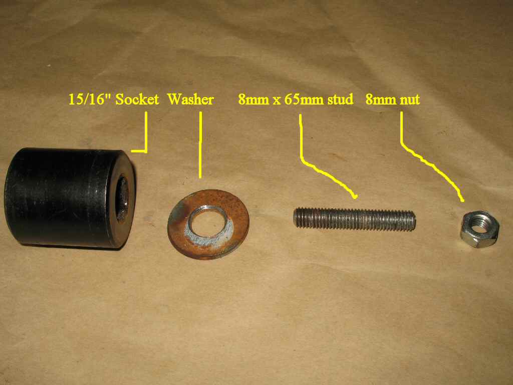
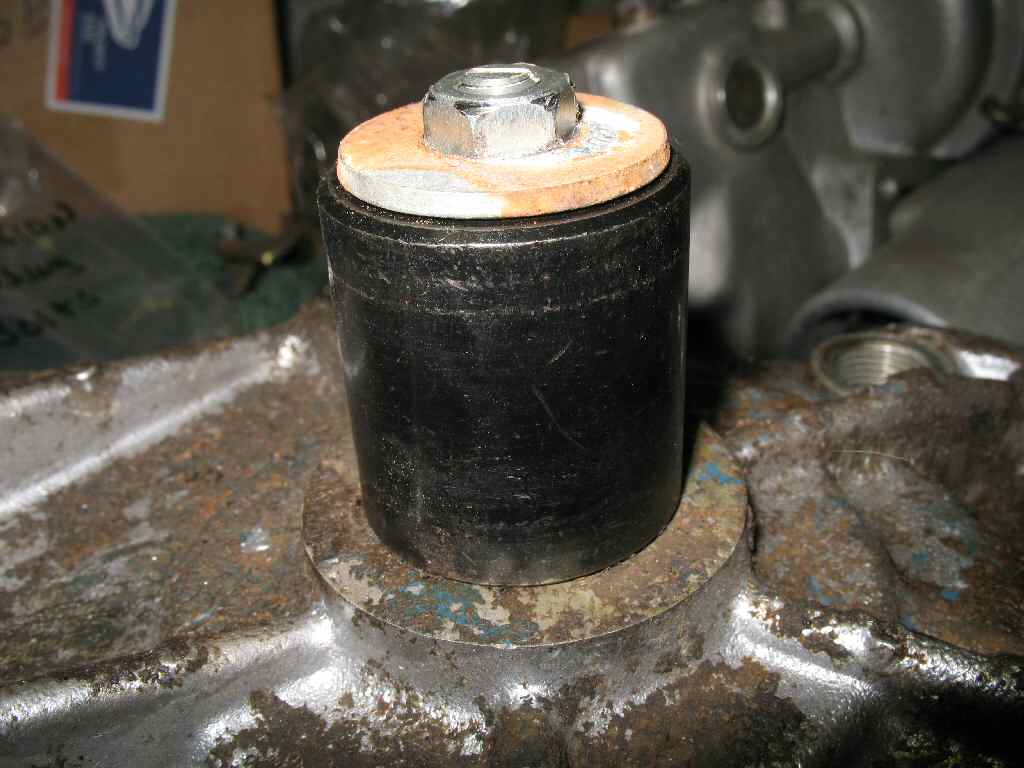
Making a T-Case Idler Shaft Remover
Fig. 6
Parts
Fig. 7
Using it
If you plan to rebuild your T-Case, one tool you
will need is a T-case idler shaft remover. While it's not truly needed, (you can drive it out with a drift), it
will make the job much easier. See Fig. 6 for the list of exotic parts you
will need. :-)
Fig 7 shows the tool in use. The stud is threaded
into the end of the shaft, the socket placed over it, the washer placed on
top of the socket, then the nut threaded on to the stud. As you tighten the
nut the stud will be pulled out of the case. Could not get any easier.
Rusted Nut/Screw Remover
I read about this tool on the
LCML early on in my rebuild, and built one that night. This thing WORKS!
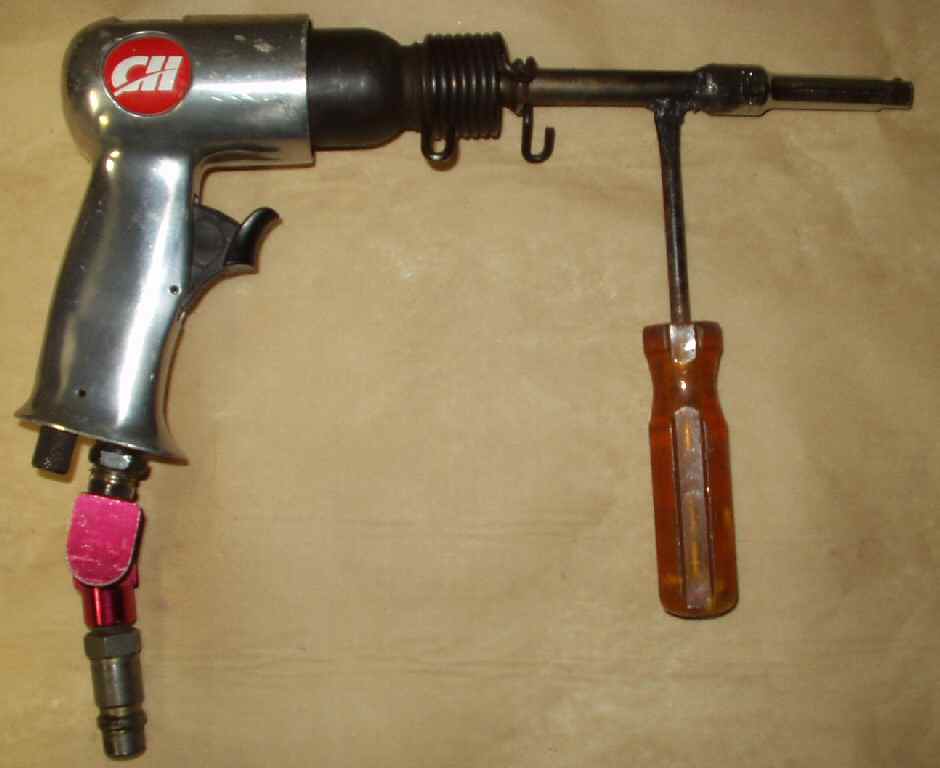
This is an air chisel/hammer with
a modified 401 shank tool. To build one you will need the following:
401 Style shank
I used an old muffler removal tool
3/8" x 3" extension
Cheap Harbor Freight
3/8" to hex bit adaptor
Cheap Harbor Freight
Hardened #2 phillips bits
IF you can find them use JIS #2 bits.
Old Screwdriver
You knew you kept those for something!
Building the Tool
Referring to the pics below cut the end of the old screwdriver off. Now cut the end off the 401 tool shank. Weld the three pieces together as shown in Fig. 1. That's it! Fig. 2 shows the tool inserted into the air hammer. Fig. 3 shows the adapters and bits. Of course you can also put normal 3/8" sockets on it for smaller nuts/bolts.
Fig. 1
Welding Parts
Fig. 2
Complete Tool
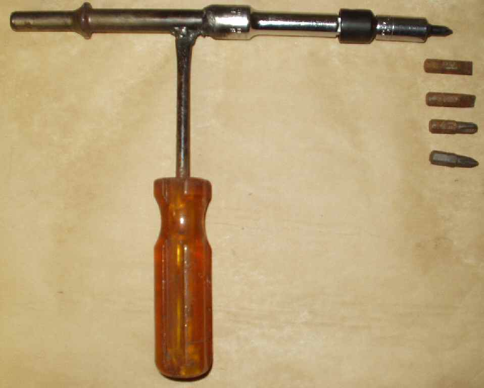
Fig. 3
Adapter/Bits
Using the Tool
The purpose of this tool is to provide rapid, heavy blows, to the fastener you are trying to loosen. These impacts will help to break the rust bond between the nut and bolt, or screw and threads. It also , in the case of phillips head or allen head screws, drives the tool tip into the head. This really helps the bit get a solid grip on the head.
To use the tool turn the air pressure down to about 35 PSI using the compressor regulator.
As always, if possible, apply lots of heat using a propane torch, or other means, to the fastener. IF you can get it red, so much the better! This one thing will really help to break the rust bond.
Let it cool down a bit, and apply penetrating oil. Let it soak for a minute or three.
Attach the appropriate bit to the tool. Insert the bit into the screw, grab the handle, apply downward pressure, (to keep the bit in/on the fastener), pull the trigger, and at the same time rotate the handle counter clockwise to loosen the fastener. The fastener will generally start turning right out. You will see rust dust dancing out around the fastener as it works.
If the fastener is stubborn: Do not use so much rotational force that the head strips! If it won't come loose easily: STOP! Repeat steps two and three. Try tightening the fastener a bit then loosing it. Basically working it back of forth. Once it breaks loose a bit, apply more penetrating oil, turn it half a turn out, apply more oil, turn it half a turn in. Work the fastener slowly out.
So what to do if it strips out, or worse, breaks off? You can try the drill it/easy out method, but the fastest way is to weld a nut on the broken fastener, then use a wrench to turn it out. The heat of the welding usually breaks the rust bond.
Pilot Bearing Removal Tool
This tool is also very easy to build. You will need the following:
Part
Where to Get
5/16" x 6" Carriage bolt
Local Hardware store
Large washer, plate, socket or section of pipe
Junk Pile
Three nuts to fit bolt
Junk Pile
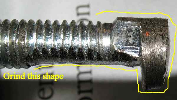
Fig. 1
Grind this shape on the head.
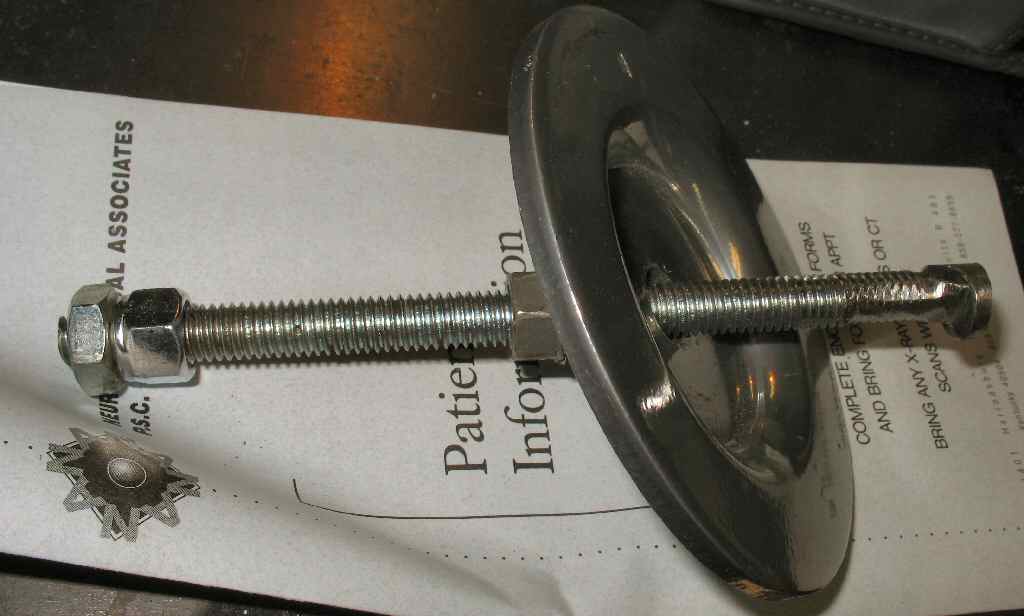
Fig. 2
Completed Tool
Refer to Fig. 1. Grind the head of the carriage bolt into the shape you see. The idea is to grind off one side of the head, then to create a lip on the other side that will engage the pilot bearing inner race.
Test fit the bolt head into the pilot bearing until you can get a good bite on the race.
If you have to make a plate, it only needs to be large enough to span the raised lip on the end of crank. Drill a hole in the center just a bit larger than the bolt.
Slide the washer/plate socket/pipe over the bolt, then put all three nuts on the bolt. Tighten the outer two nuts against each other toward the end of the bolt. See Fig.2. This completes the tool.
Insert the ground down head of the bolt into the pilot bearing until it engages the inner race. Pull back on the bolt, and spin the inner nut down until it engages the washer/plate/socket/pipe, and firmly presses it against the end of the crank.
Now use one wrench on the outer nut so you can hold the bolt still, and another wrench to tighten the inner nut against the washer/plate/socket/pipe. As you tighten the inner nut the pilot bearing (God willing) will start sliding out. You may need to reposition the tool to the other side of the bearing if the bearing tries to turn sideways in the crank.