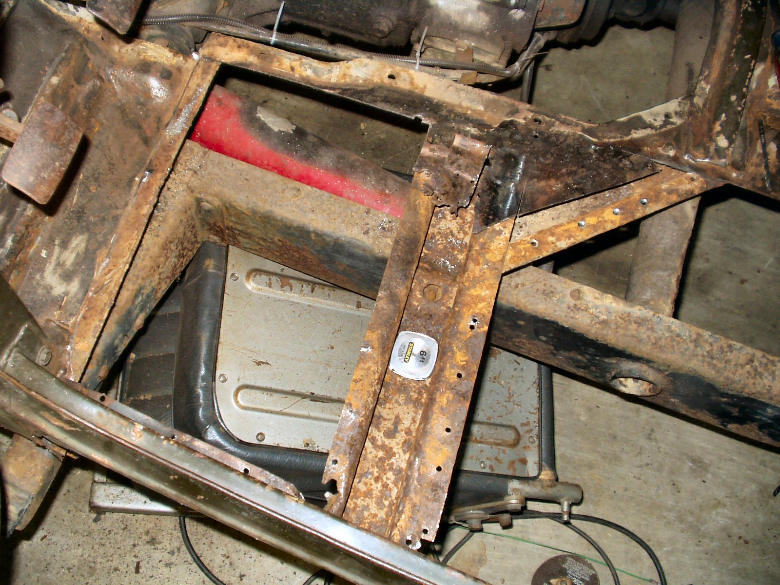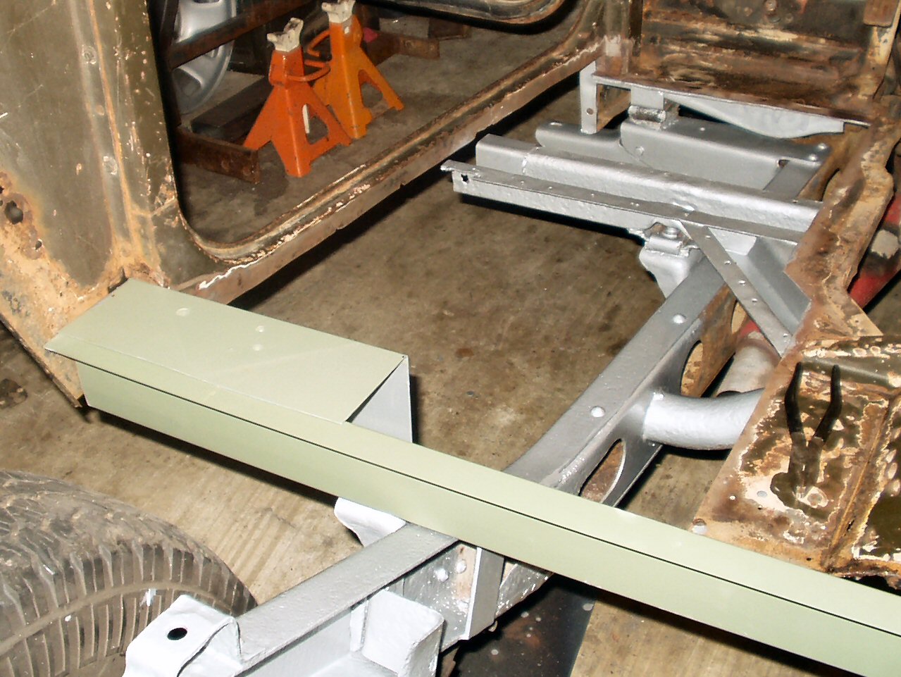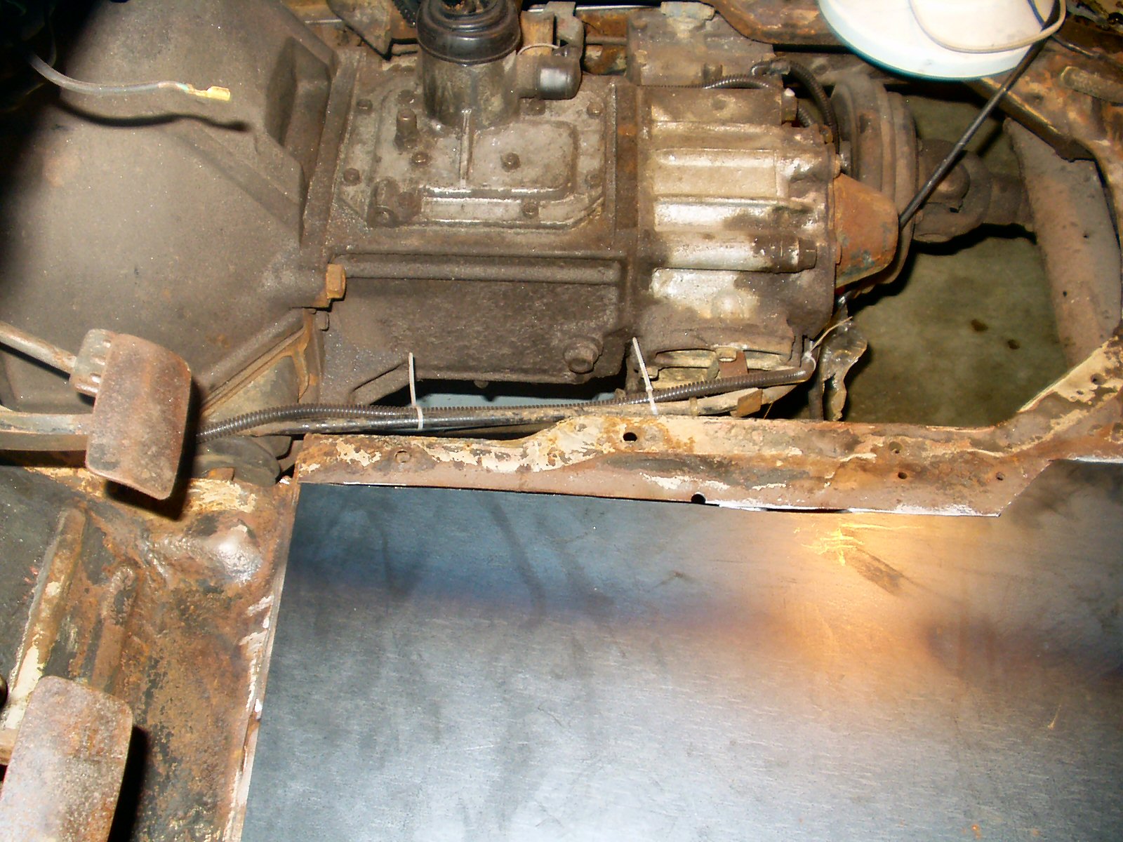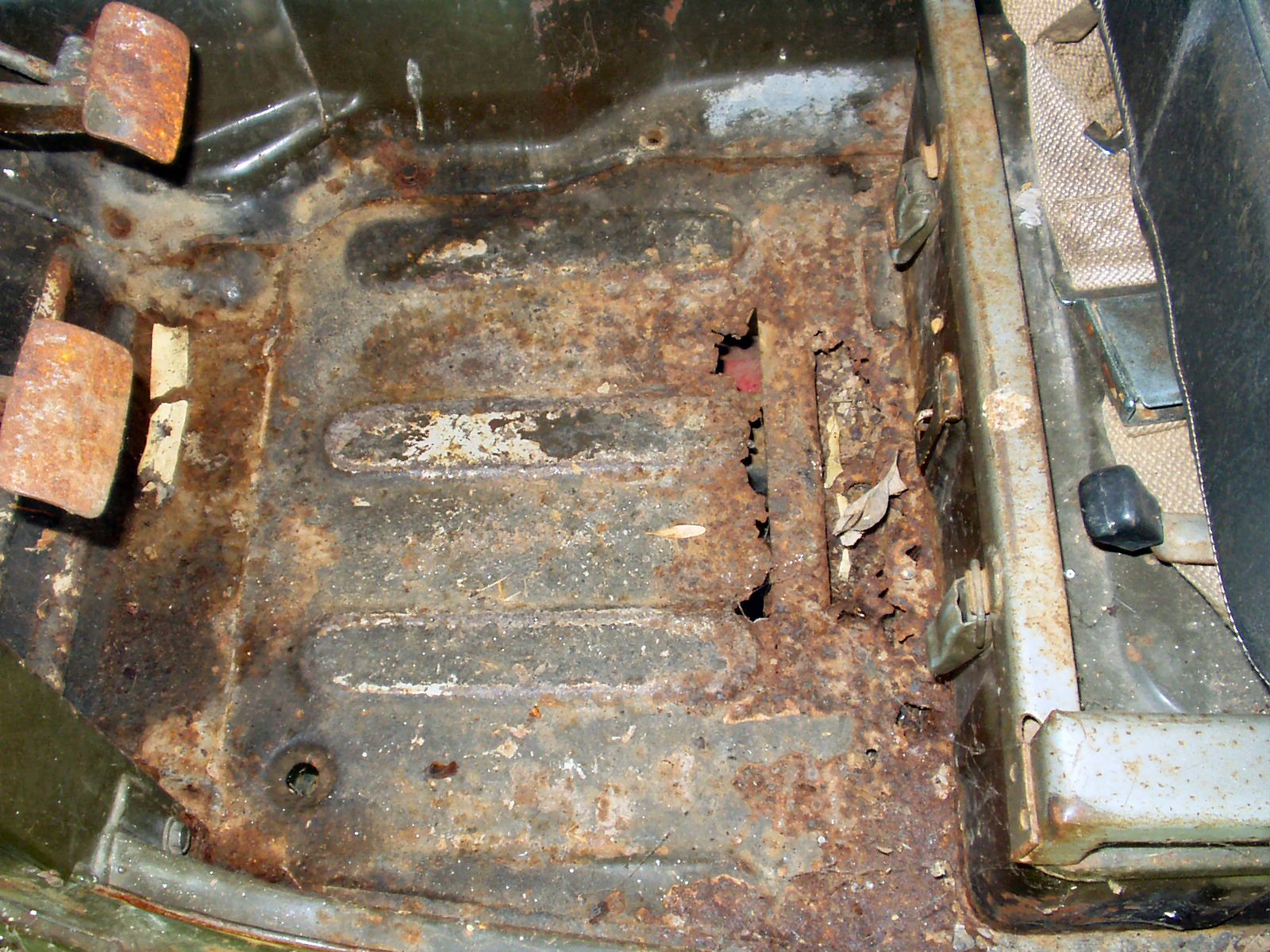
Fig. 1
Flintstone powered!
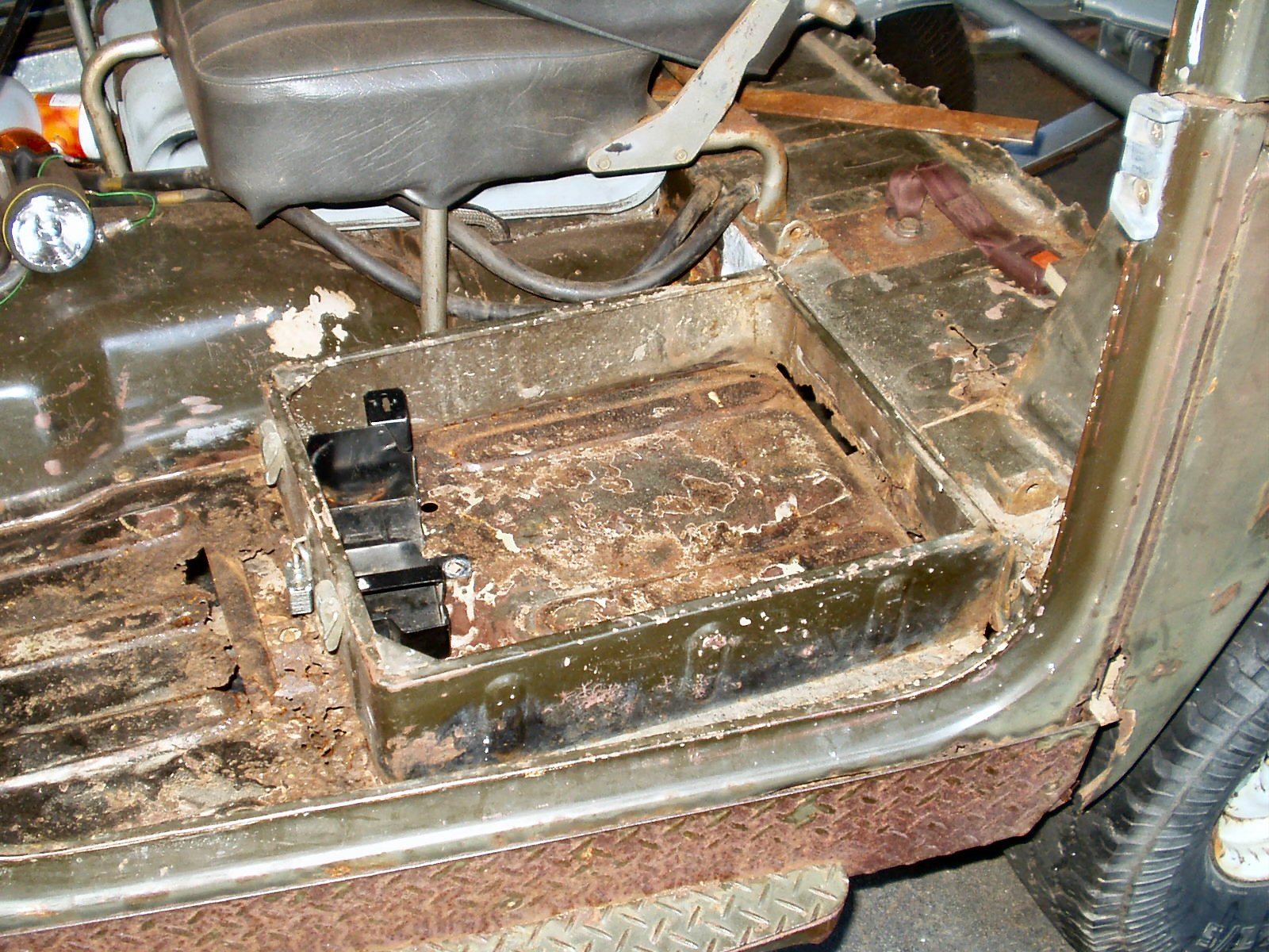
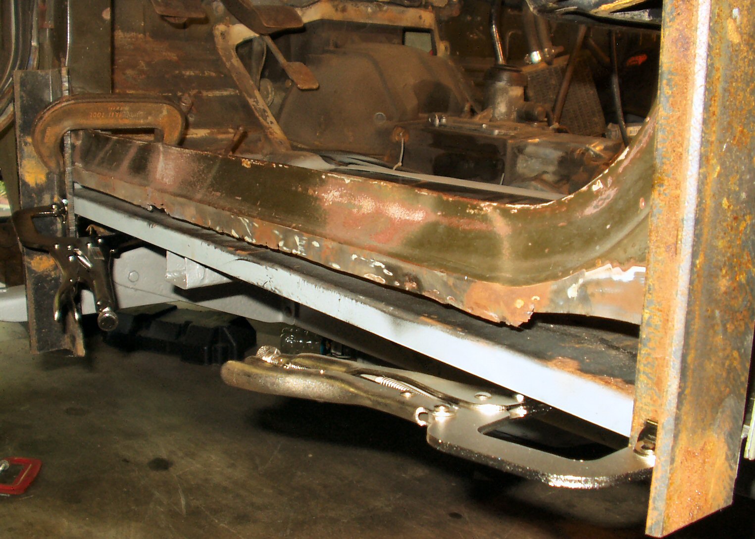
Fig. 2
Tool Box
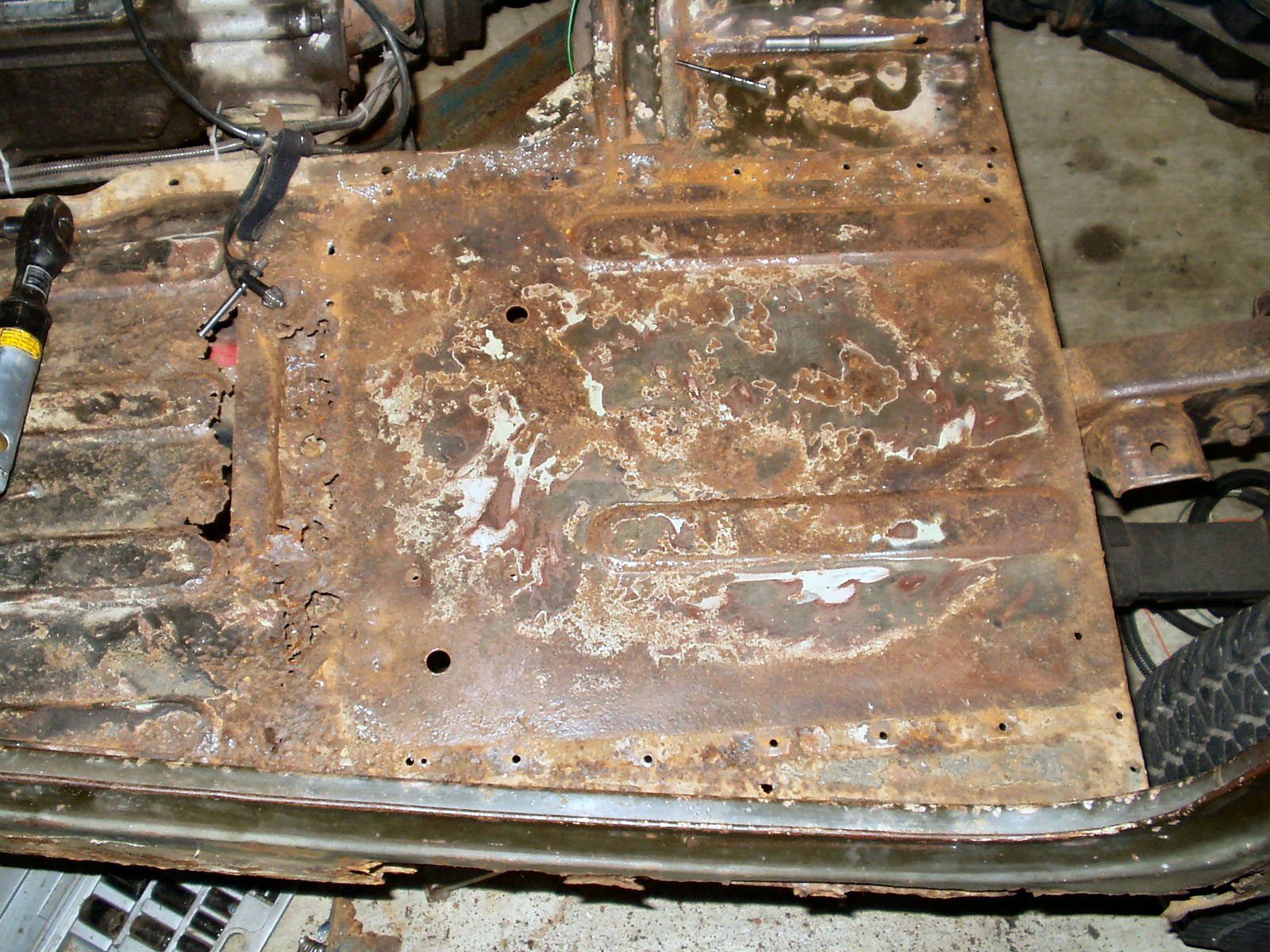
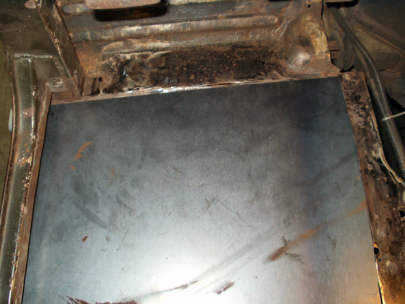
Fig. 3
Tool Box Removed
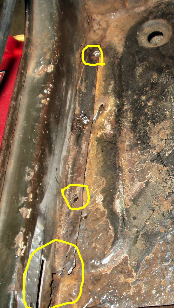
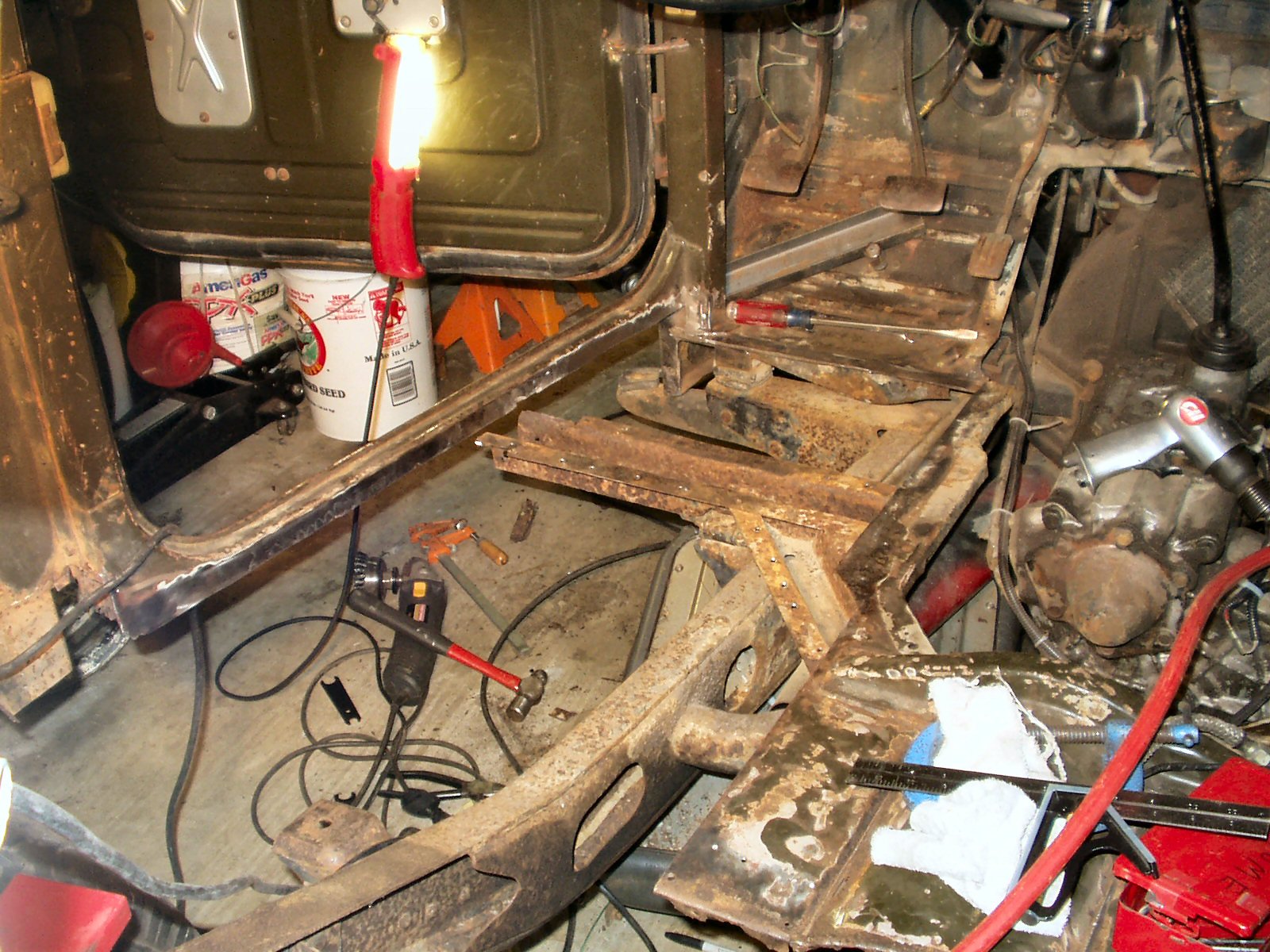
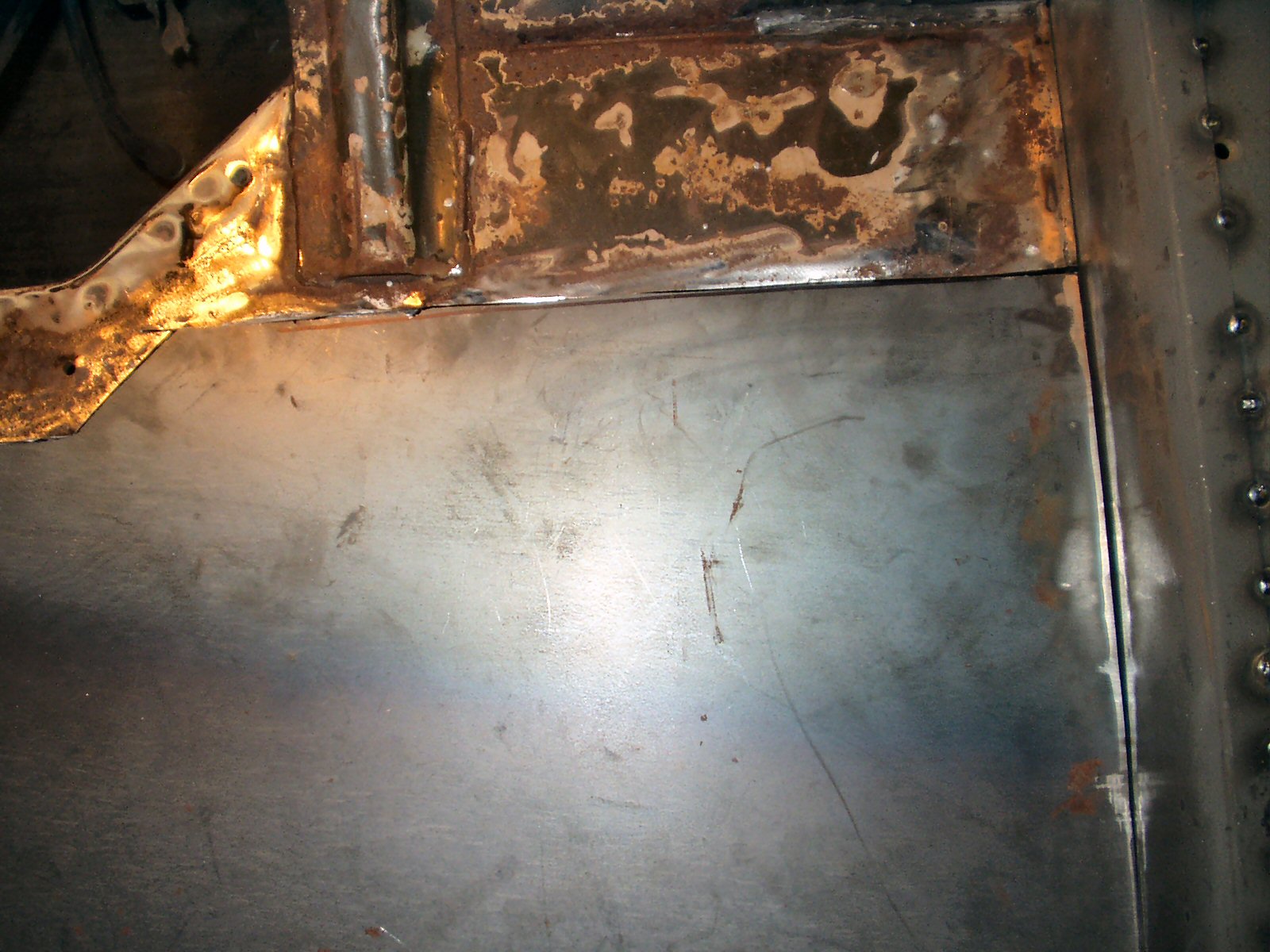
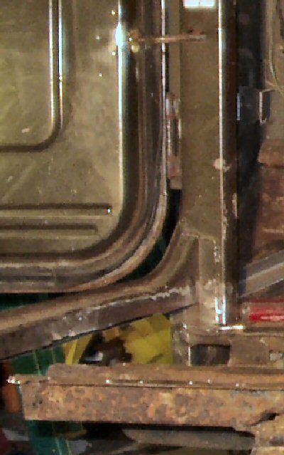
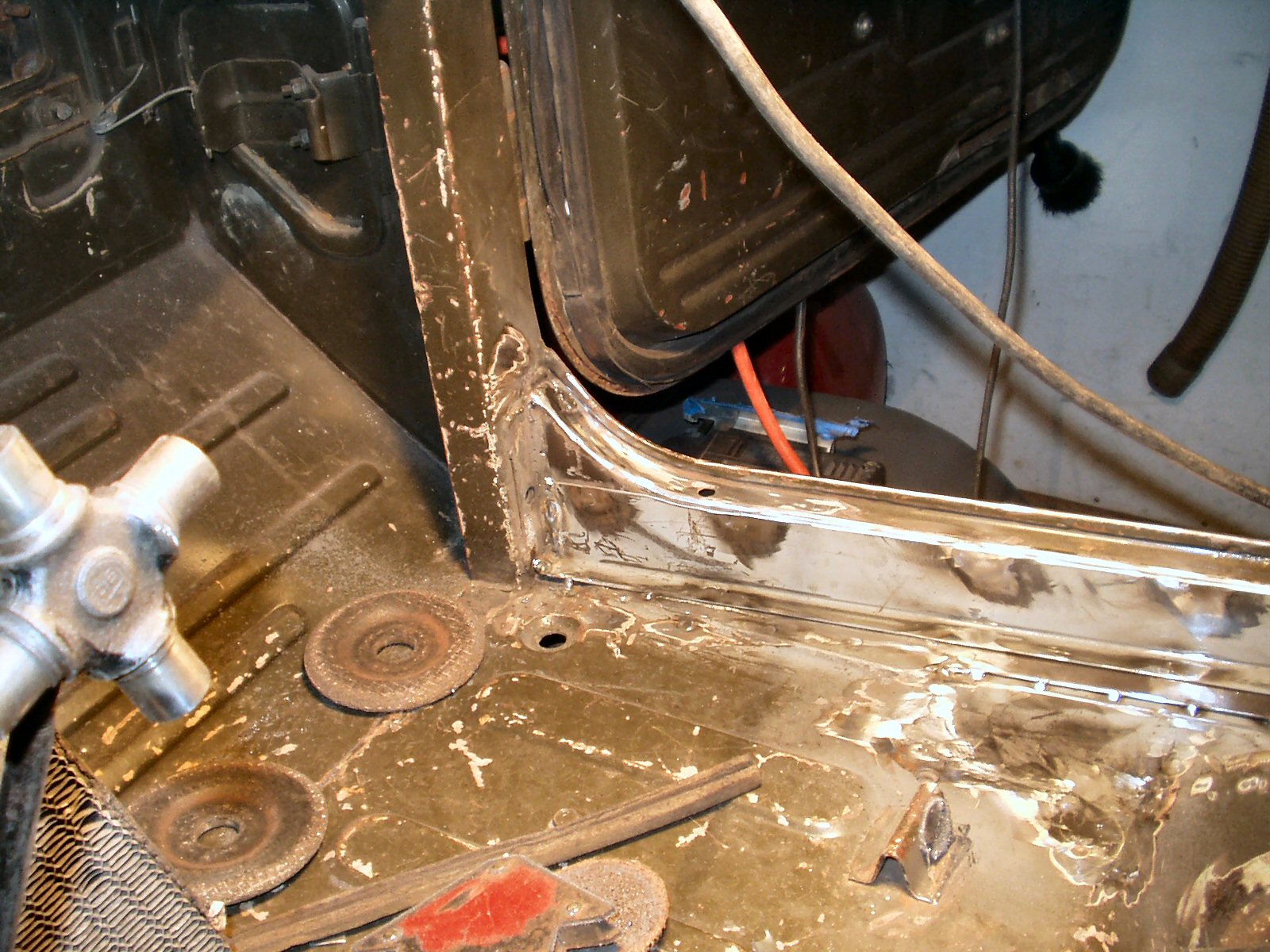
Fig. 4
Inner Rocker Trimming/Removal
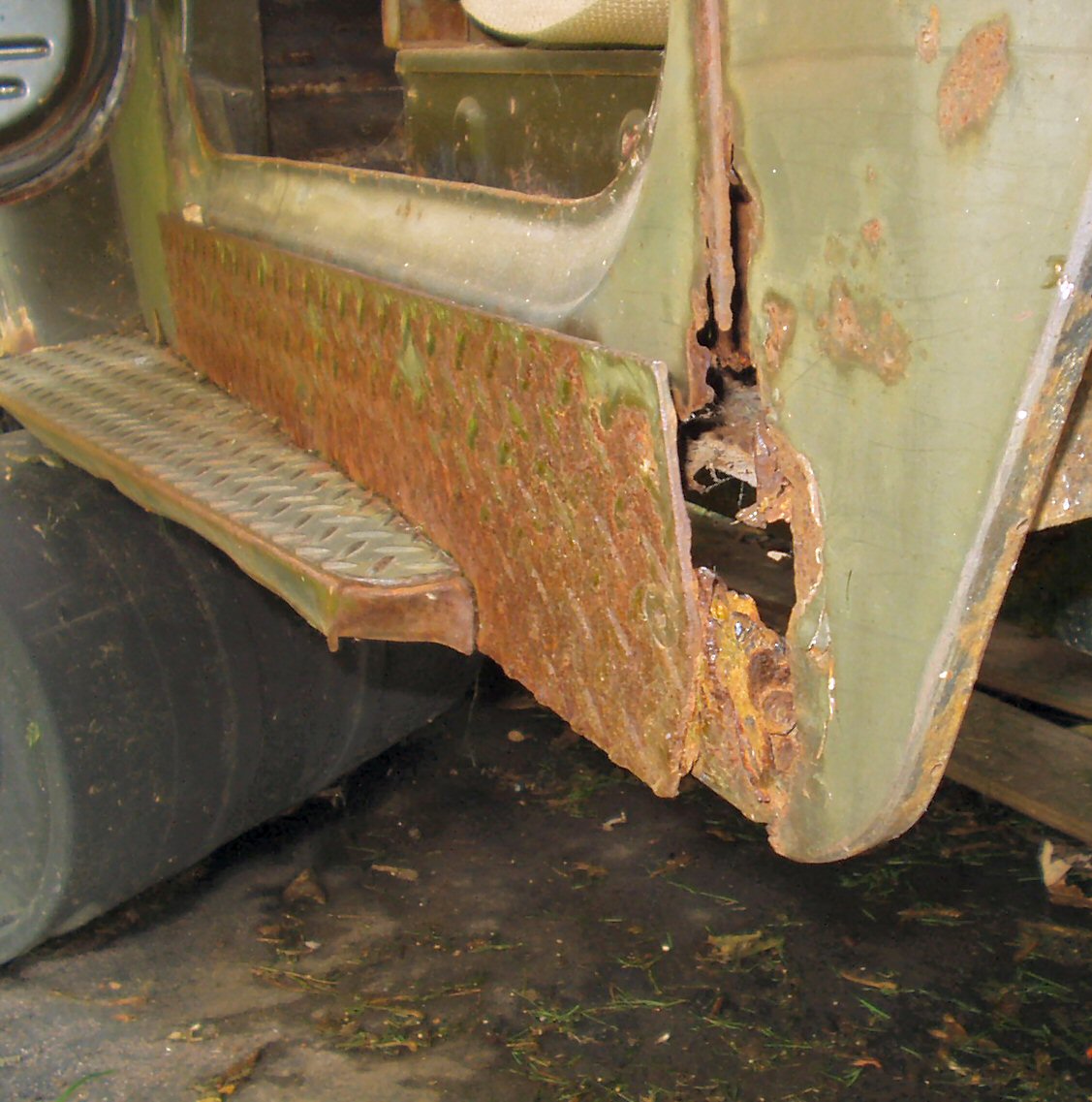
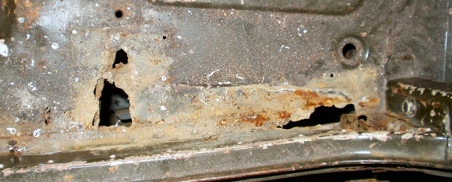
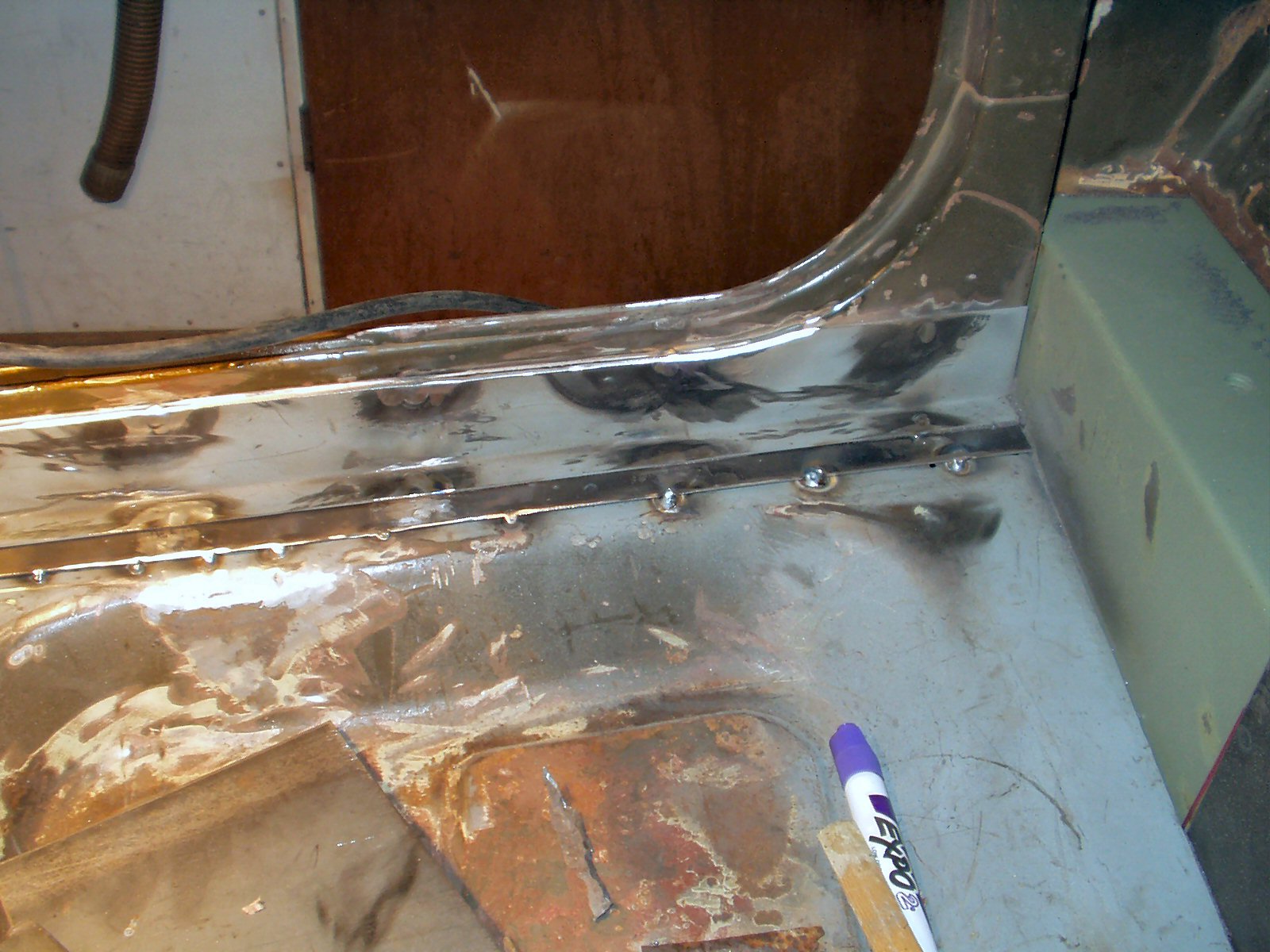
Fig. 5
Armor over what?
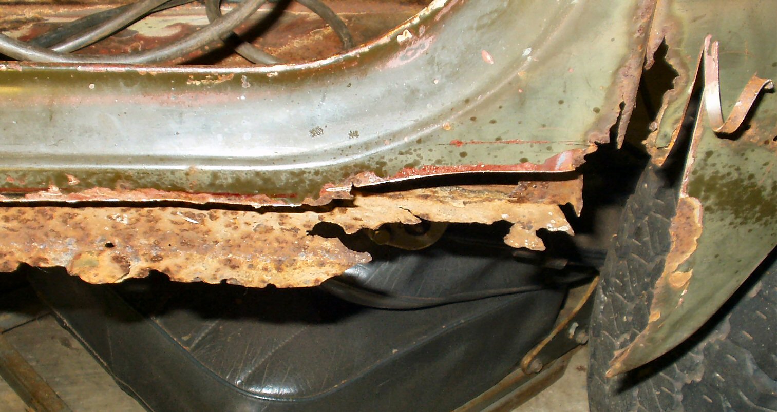
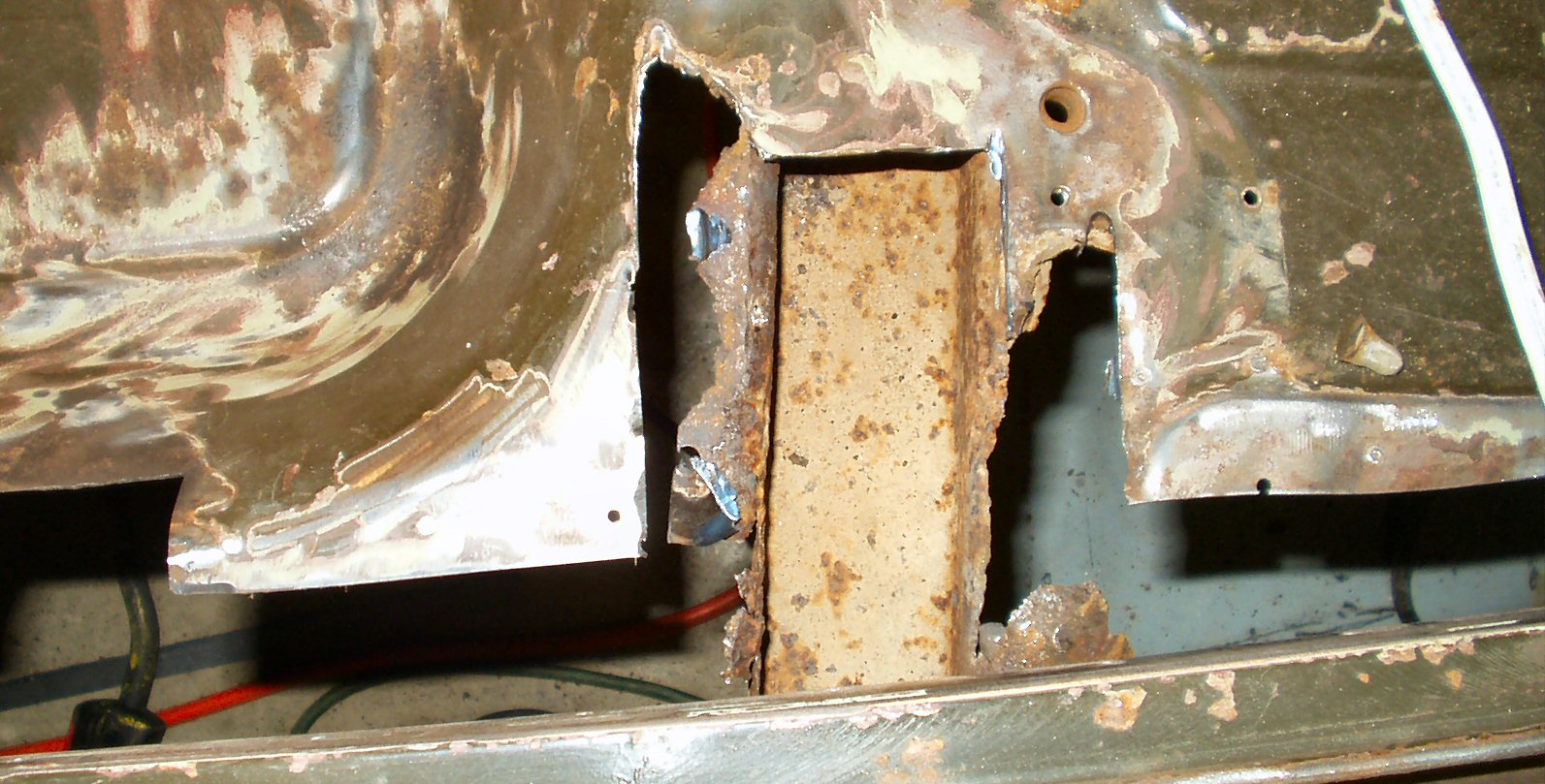
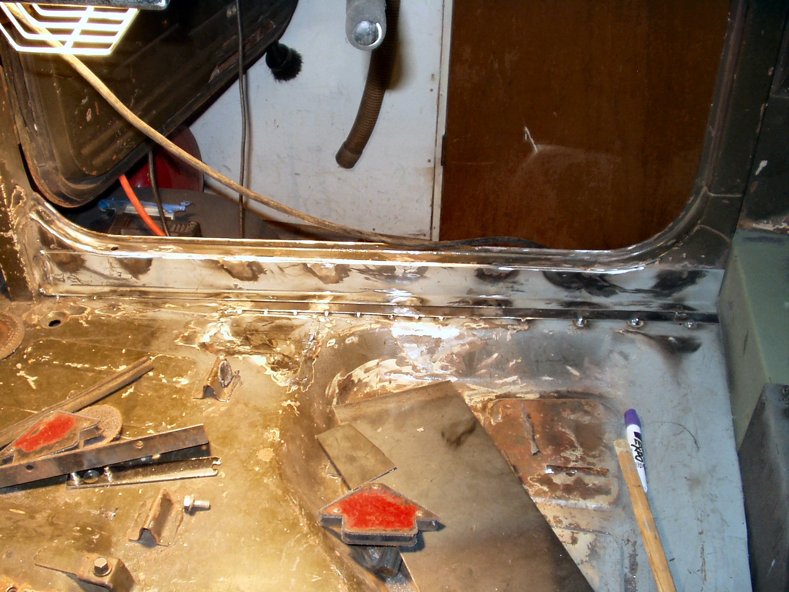
Fig. 6
Trimming to 'Good ' Metal?
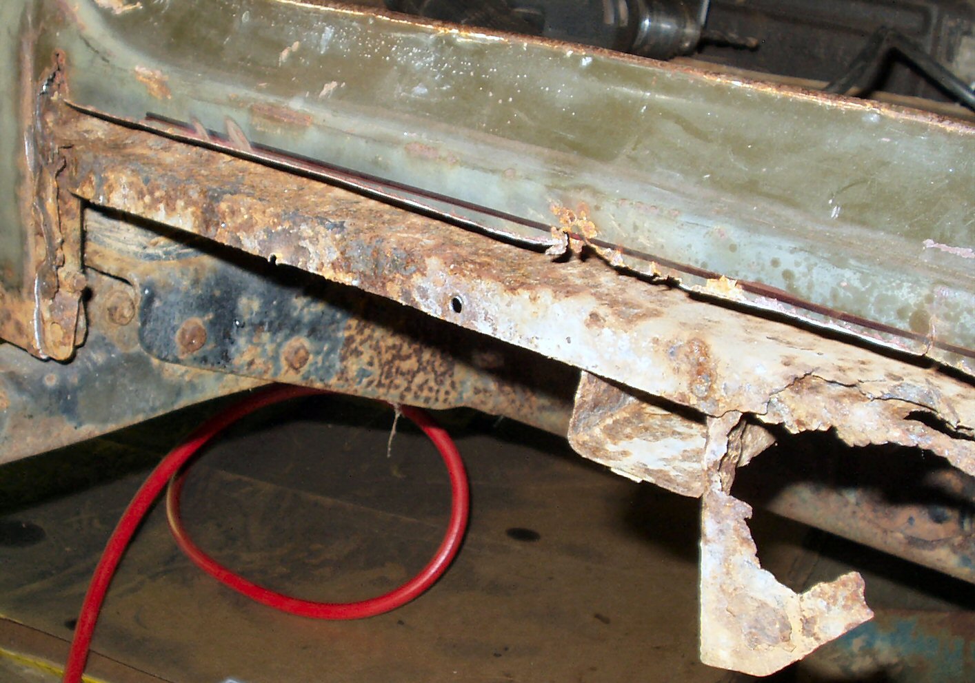
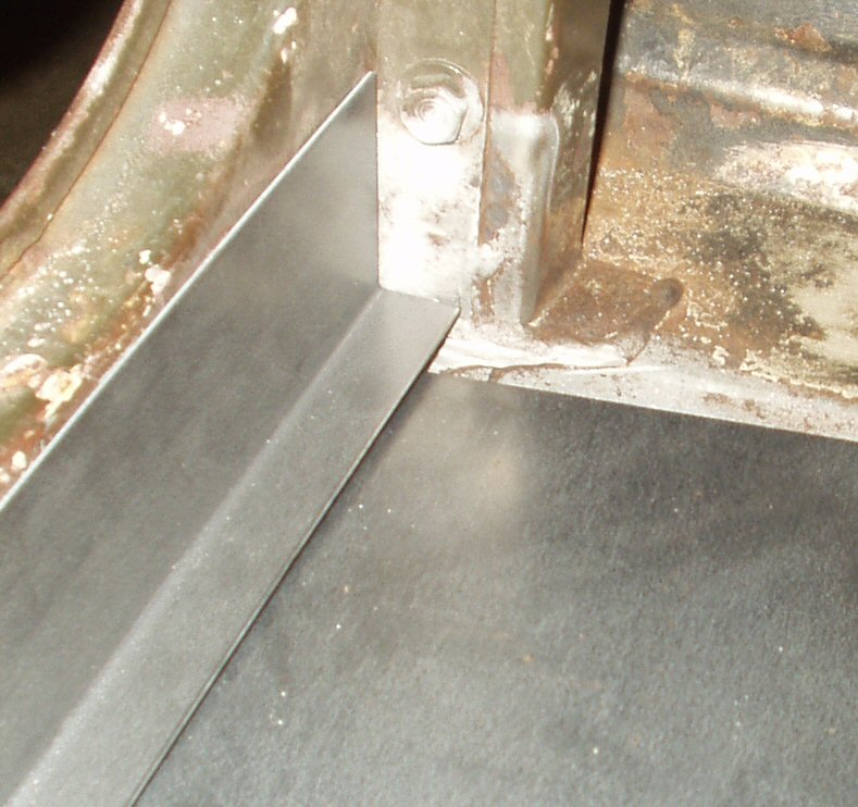
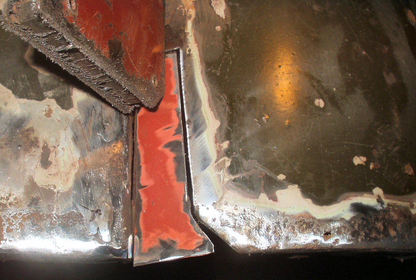
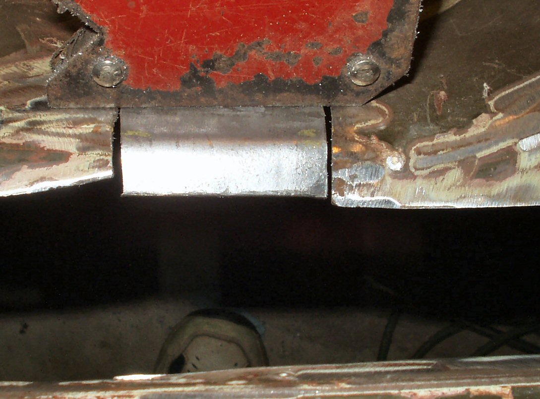
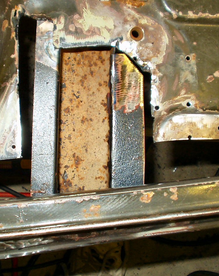
Fig. 7
Armor Removed
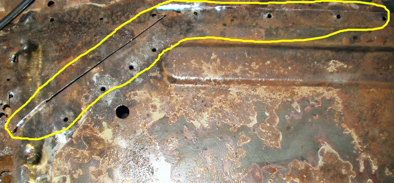
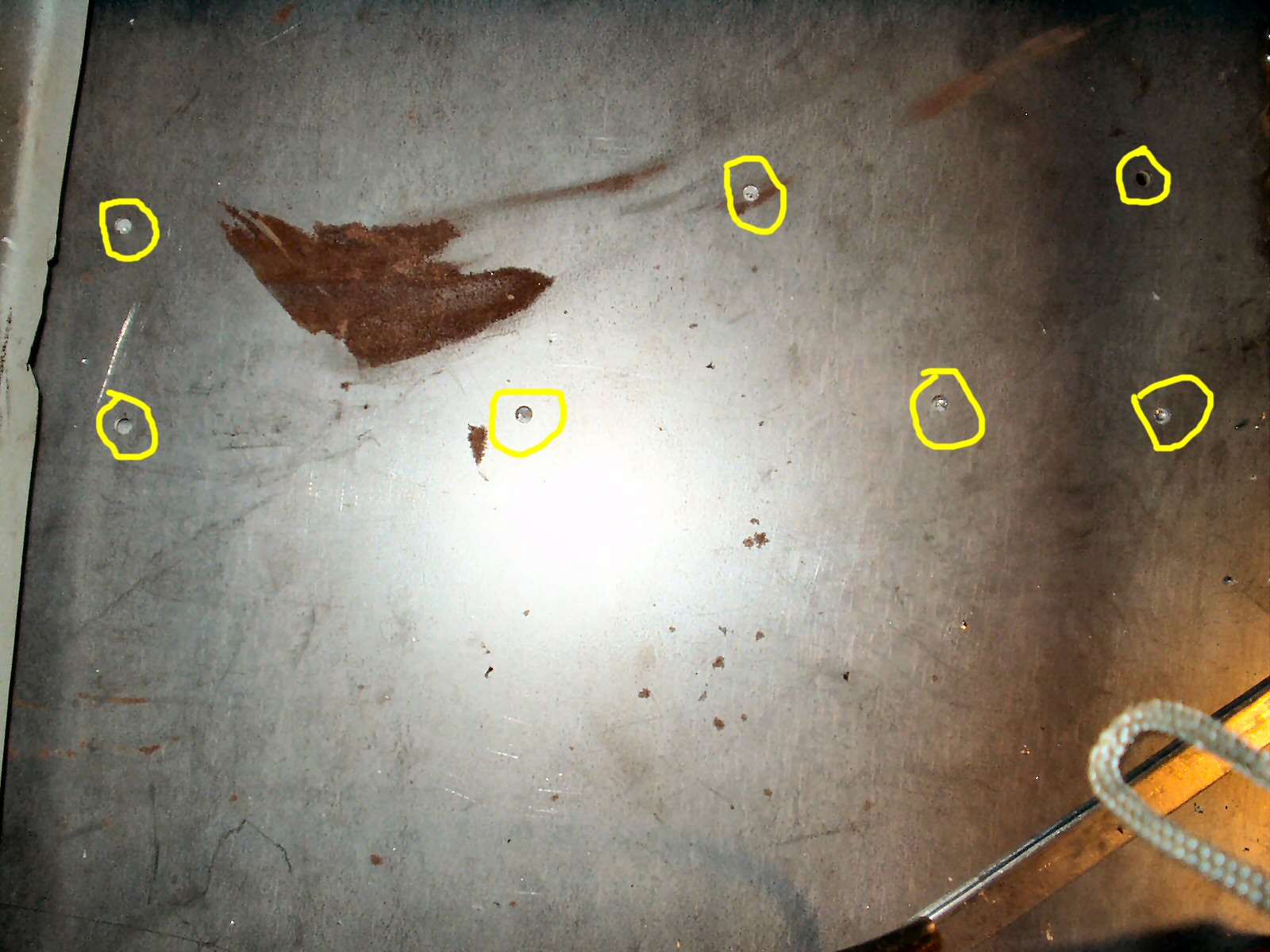
Fig. 8
Drilling out floor support rivets
Fig. 1 Flintstone powered! |
Fig. 2 Tool Box |
Fig. 3 Tool Box Removed |
Fig. 4 Inner Rocker Trimming/Removal |
Fig. 5 Armor over what? |
Fig. 6 Trimming to 'Good ' Metal? |
Fig. 7 Armor Removed |
Fig. 8 Drilling out floor support rivets |
At this point in the project I was having serious doubts about my decision to 'fix' this tub! I was really afraid that the cowl was rusted badly, but when I removed the front floor board it was not as bad as it looked. I started by removing the seat then drilling out the spot welds that held the tool box to the floor. Some were easy but others were a pain! I had already removed the ones holding it to the mid bed. See Fig. 1-3. I put the tool box shell into the de-rust tank knowing I will have some metal to weld back into it later.
Next I cut the inner and outer rocker panels up to good steel exposing what was left of the outer edge of the floor. See Figs. 4-7. Next I drilled out all the spot welds holding the floor to the rocker panels and floor support channels. Whew! That took awhile! I could now use a cut off wheel on the grinder to cut the floor loose around the tranny and PTO humps. See Fig. 8.
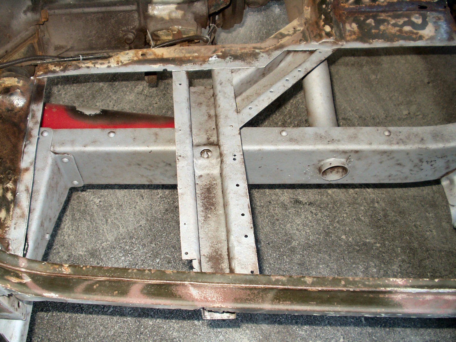
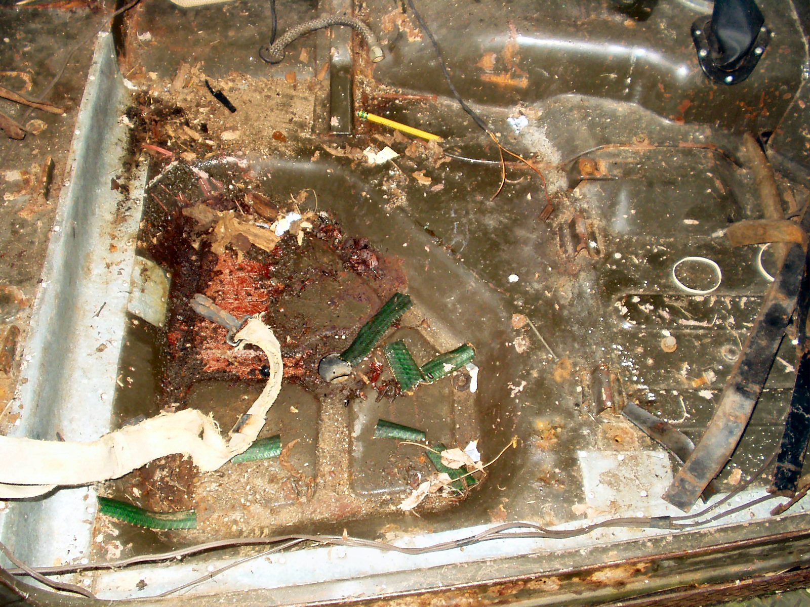
Fig. 9 Floorboard Removed |
Fig. 10 Overall View |
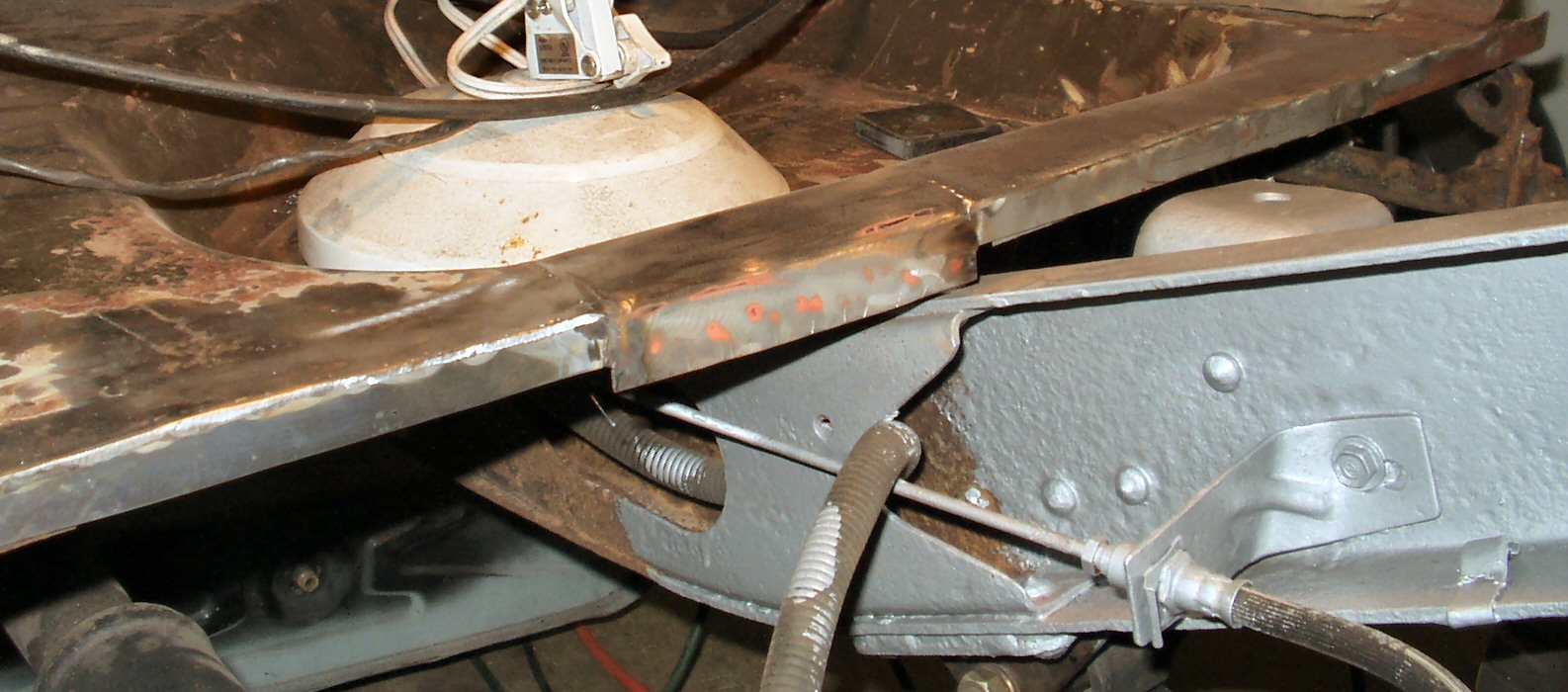
Fig. 11 After Sand Blasting |
Fig. 12 Repairing the Floor Support |
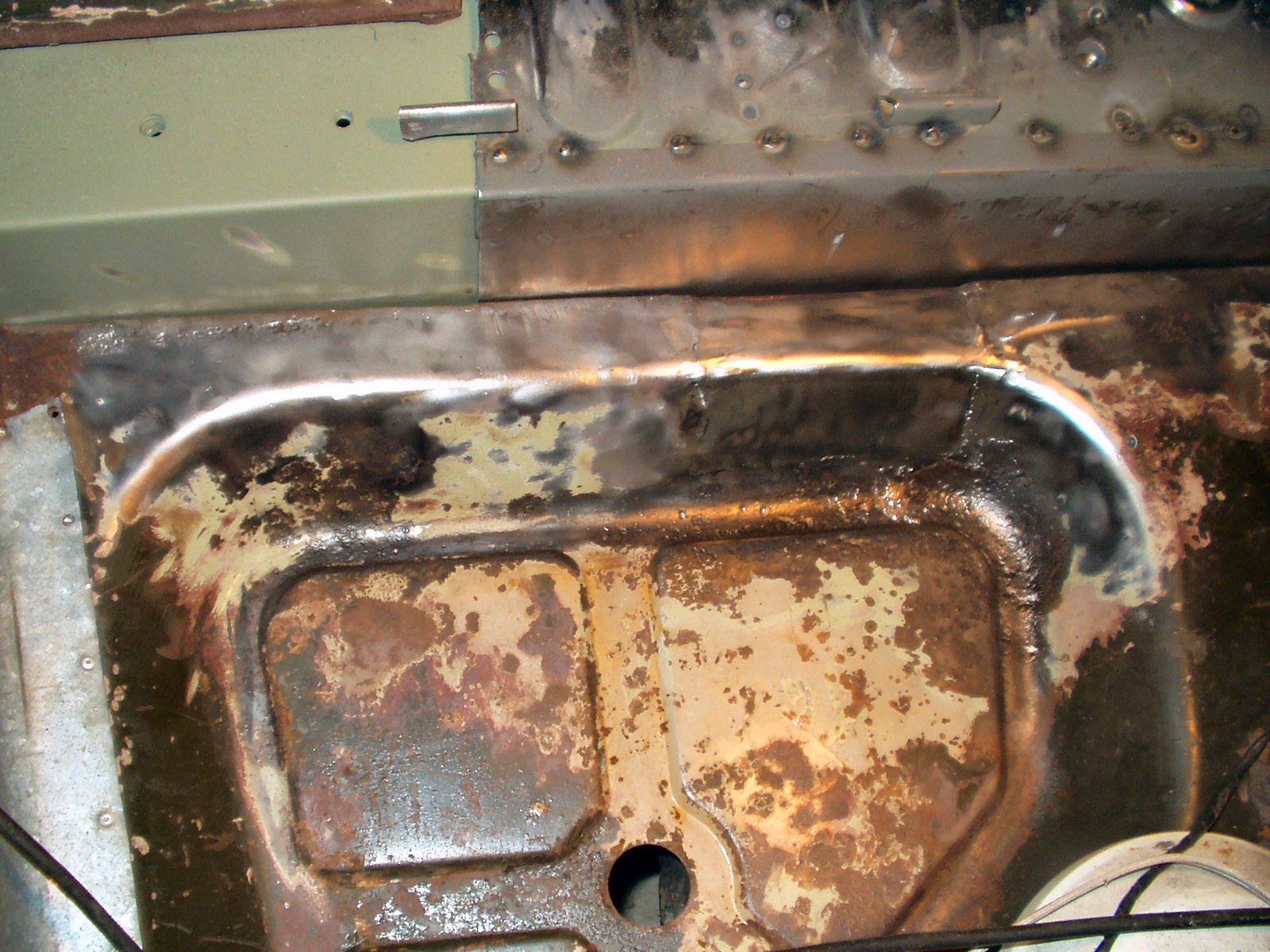
To get the floor loose I had to grind off several welds between the cowl and floor. Finally I could lift the floor section out. See Figs. 9-10.
At this point I rolled the truck out of the garage and sand blasted the exposed channels and frame. See Fig. 11. The main floor support channel was rusted badly only on the end and was easy to fix. See Fig. 12.
Fig. 13 Rust Bullet Applied |
Fig. 14 Aligning the floor edge to the body |
Fig. 15 New Floor Rear Section |
Fig. 16 New Floor Front Section |
I then applied a coat of Rust Bullet to the exposed sections of frame. See Fig. 13. Keep in mind that I plan on pulling the entire body off, AFTER I get it stable enough. Then I can properly do the entire frame.
Ok now I could start welding in the new floor. I had a local shop bend up a 14 ga sheet with a 3/4" down flange on the rocker side and back. Took me a while to figure out the angle of the cab floor but for those that want to know: Using the center support as the 'base' line the cab angles in at an 87 degree angle. I had them cut it an inch oversize so I could play with it if I had to. To trim it to fit I placed it in the truck, used clamps to ensure it was in the right place, then got under the truck with a marker and marked it on the bottom around the supports and the tranny hump. A jig saw with a 24 TPI blade was used to cut the sheet to size. This took several tries... After the final cut I primed the bottom with weld thru primer and placed it back in the truck. I used a couple of large pieces of angle iron clamped to the door post and cowl to align the floor section with the outside of the rocker. Figs. 14-17 show the floor sheet cut, clamped in place and ready to weld in.
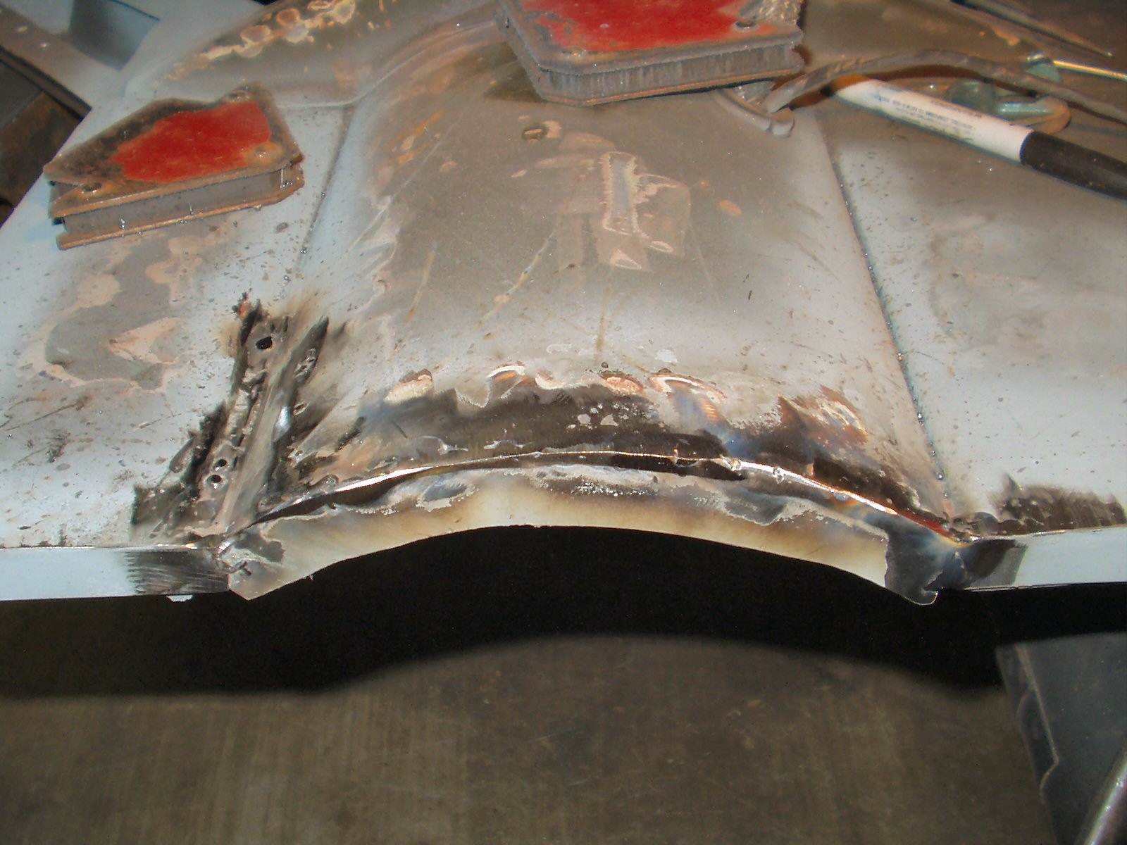
Fig. 17 Tranny Side Edge |
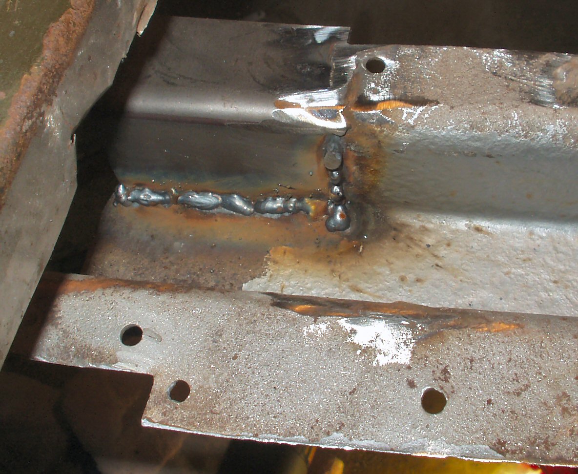
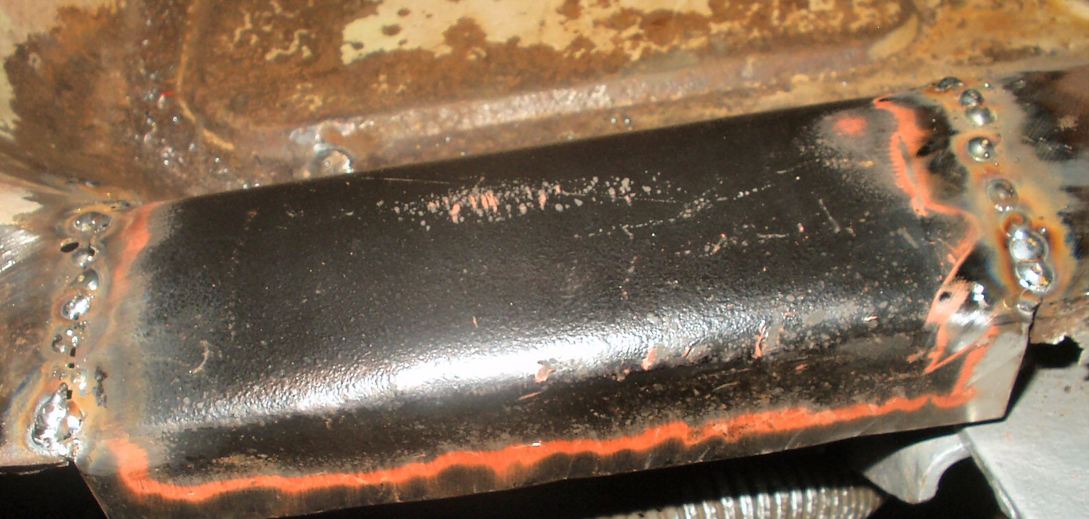
Fig. 18 Plug Welding the Floor |
Fig. 19 Repaired |
Next up was spot welding the floor around the cowl and tranny hump side in a couple of places to hold it firmly in place, then drilling holes in the floor into the floor support. See Fig. 18. These were then plug welded and ground smooth. After that several passes were made spot welding the floor around the edges. I didn't weld the back edge as I know I have a lot of alignment work to do on the various pieces that fit here. I need to get the wheel wells and cargo floor in place so it all lines up correctly. See Fig. 19 for the completed repair before grinding down the welds.
Fig. 20 Starting the trimming |
Fig. 21 Trimmed Rocker |
Fig. 22 Repair panel |
Fig. 23 Welded in |
I don't have a lot of pics of the drivers side inner rocker repair but here is what I did. Figs. 20-21 shows the inner rocker panel and how I used the air shear to trim the panel leaving about 1" of good metal. I had a metal shop bend 2 panels , one for each rocker, 34" long and 3" wide with a 3/4" lip. See Fig. 22 for a pic of the panel in place before plug welding. After wire wheeling the lip to bare metal , I primed with weld through primer then drilled holes in the panel for plug welds. See Fig. 23.
Fig. 24 Fixing the PTO Hump |
Fig. 25 Fixing Pan Flange |
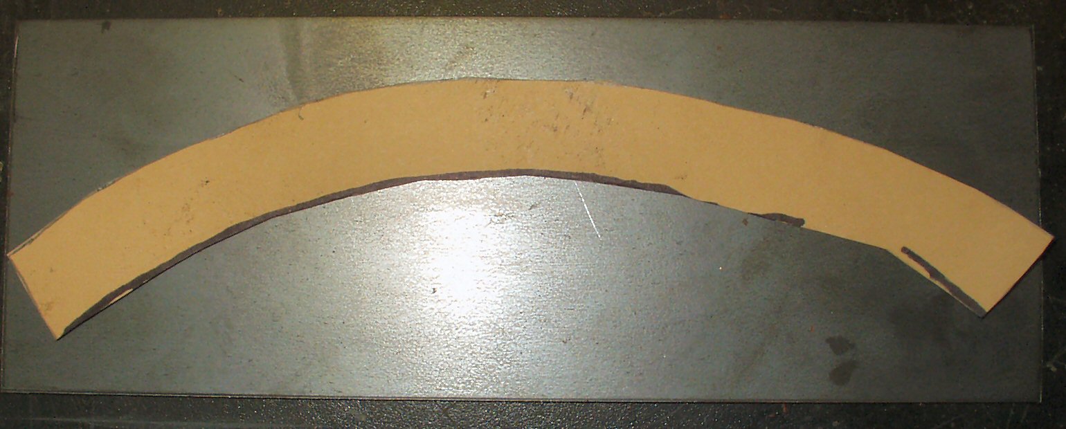
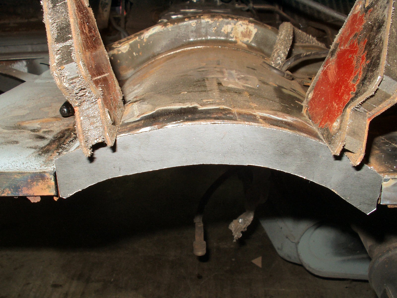
Fig. 26 Making curved piece template |
Fig. 27 Ready to Weld |
Fig. 28 Curved Piece Welded in |
Ok so moving on to the PTO hump. I had a couple of small holes rusted through here also. I cut out the bad area with my jig saw, made a patch panel and tacked it in. See Fig. 24
Now that the hump section was fixed I used my air shears to cut some 3/4" strips from 16 ga scrap I had. I welded these to the back edge of the floor pan all the way across to give the mid bed and center channel end pieces a solid place to be attached. See Fig. 25. I will drill a series of 1/4" holes so I can plug weld through them to the center channel later.
I had to cut the curved tranny hump piece out with the jig saw. I first made a template with cardboard by holding it up against the end and marking the inside with a pencil. I then measured down 3/4" and made a second curve. I cut it out with scissors then laid it on a piece of scrap and traced around it. See Fig. 26. Next I welded it in place. See Fig. 27-28.
Fig. 29 What I started with |
Fig. 30 Gas Tank Area Repair |
Fig. 31 Cutting out the Rust |
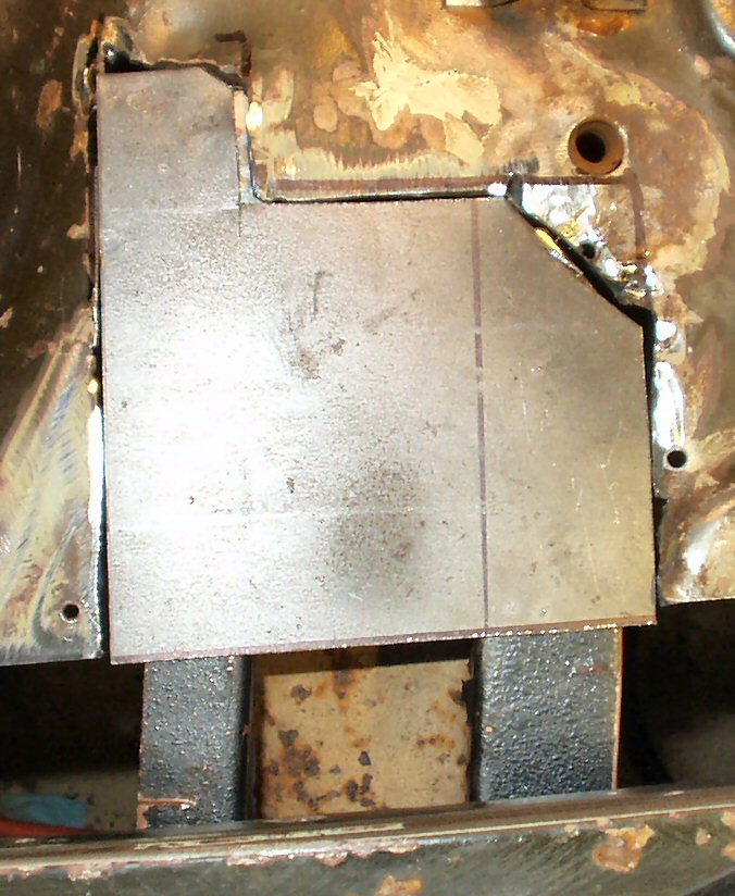
Fig. 32 Patch Panel Tacked In |
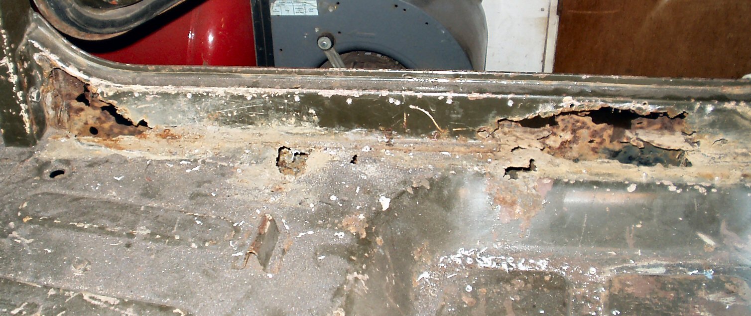
There were so many holes in the floor pan I didn't know where to start! See Fig. 29 for what I started with. Since I was also working on the main channel and had to have a solid edge flange to weld that to I started on the passenger side area where the gas tank lies. There were many holes here that were rusted through and several more where the PO had drilled holes to put in the 'stove pipe' patch panels. See Fig. 29 and Fig. 35. I started by cutting out the worst area. See Fig. 31. Once that was cut out I flattened the piece on the anvil then used that to mark out a patch panel. Next I used the anvil to shape the curve then tacked it in place. See Fig. 32.
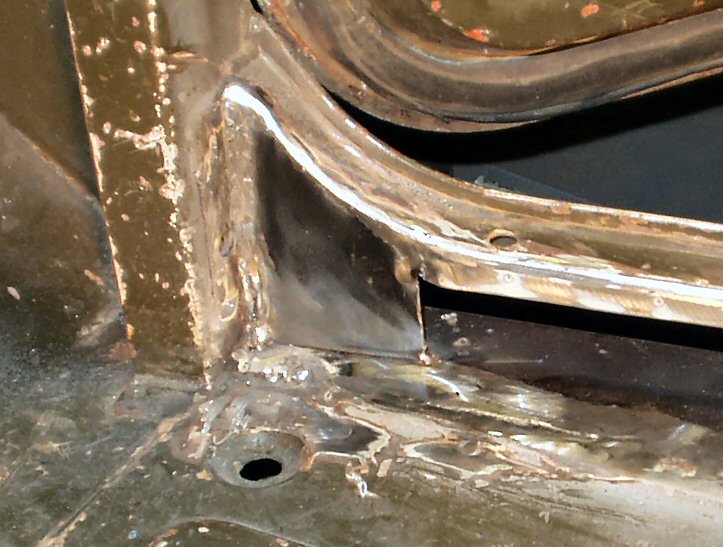
Fig. 33 Bending the Back Edge |
Fig. 34 All Ground down |
Next I bent the edge down to make the flange the center channel will be attached to. See Fig. 33. I also welded up all the rust holes and drill holes to make a good solid section. See Fig. 34.
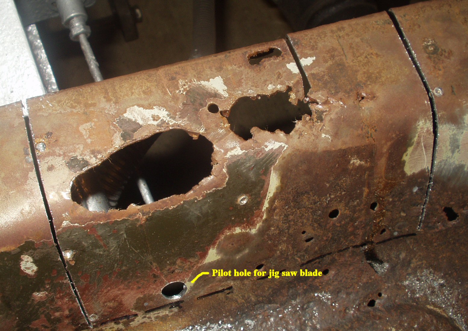
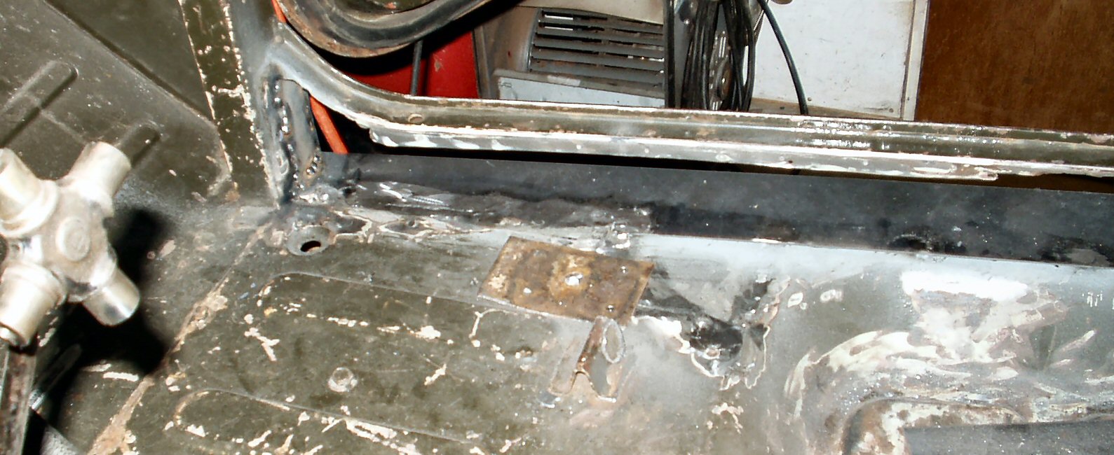
Fig. 35 Stove Pipe Repair |
Fig. 36 Worth Repairing? |
Fig. 37 Floor Rot |
Fig. 38 Cutting out Rust |
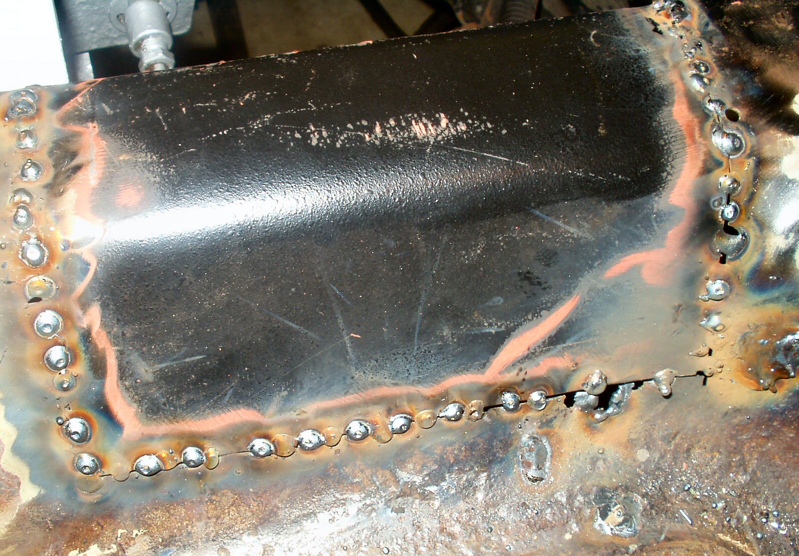
Fig. 39 Patch Panel 1 |
Fig. 40 Support Repair |
Fig. 41 Patch Panel 2 |
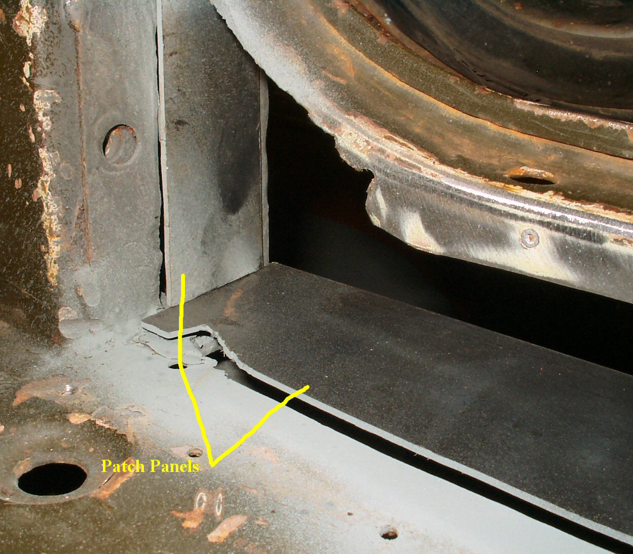
Fig. 42 Patch Panels 3-4 |
Fig. 43 Patch 4 Welded In |
Fig. 44 Rocker Patch 5 |
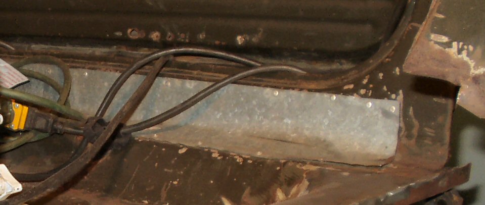
This area needed a lot of work. The PO before my brother had used galvanized stove pipe to "repair" the floor. See Fig. 35. After removing the repair I could then see what was under it. See Fig. 36. Ok by now you know the drill, cut out the rust, wire wheel to get the paint off, prime the edges of overlapping panels, cut the patch panels and finally weld them in place. Fig. 37 - 44.
Fig. 45 Inner Rocker Patch Front |
Fig. 46 Inner Rocker Patch Rear |
Fig. 47 All Complete! |
I had my metal shop bend up another piece 34" long, 3" wide and with a 3/4" lip. I cut and trimmed this to fit the edge of the old floor and welded it in place. Next I worked on the rockers themselves. I had to make a triangular patch panel to fit the inside against the cowl. See Fig. 44. Now I could weld in the inside rocker patch panel and tie it to the floor. See Fig. 45-47. All Done! What a difference... That wraps up the floor repairs.
Hosted by Global Software, Inc.
©1998 - 2023 Mark C. Baker Web Designer
Please: No part of this web site may be used without express permission... email mbaker@globalsoftware-inc.com for permission.