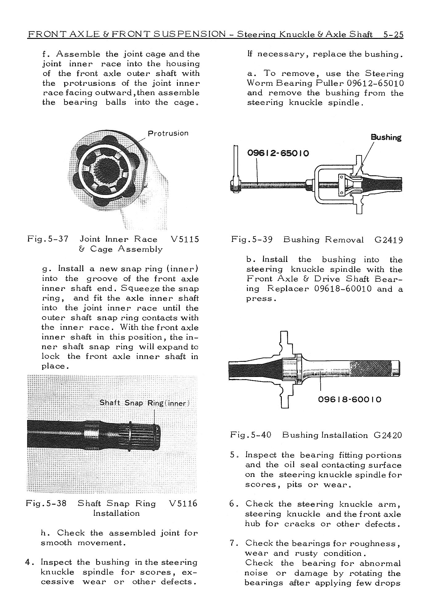
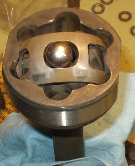
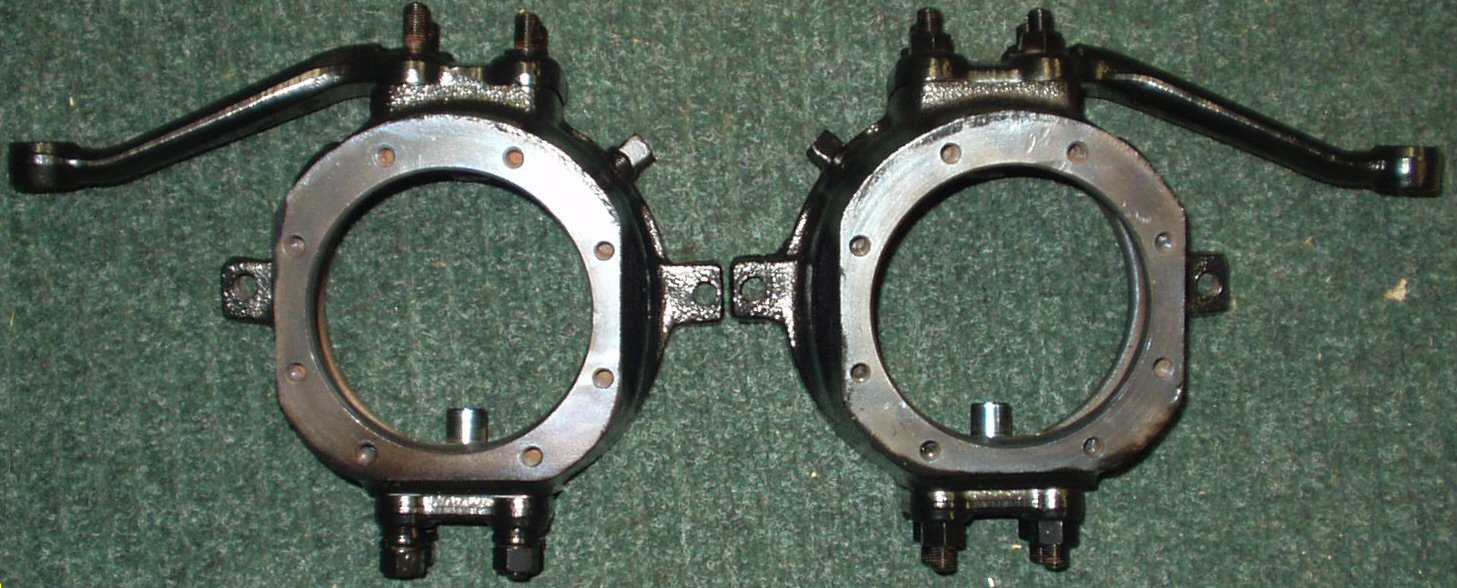
Home

1971 Body/Chassis FSM

1971-74 F Engine FSM

Page Index


Assembling the Knuckles


Prepping the Knuckles for re-assembly

Tools Needed

Tools
Description/Job
Snap Ring Pliers
For installing the snap ring at end of axle
Flat ended Brass Drift or Punch
To help re-install the Knuckle races
BFH
To be used with the drift or punch for the above job and to beat on whatever is handy when something doesn't work right. I use a long handled 3 lb sledge.
17 mm 6 point socket
For the steering arm and lower knuckle bearing retainer nuts and the tie rod end castle nuts.
14 mm 6 point socket
For installing the banjo connector bolt for the brake line manifold
10mm 6 point socket
For installing the 8 small bolts holding the ball seals on the back of the knuckle.
12 mm 6 point socket
To installing the brake line manifold from the brake backing plate and to remove the wheel cylinders from the backing plate.
17mm and 10mm flare nut wrenches
For installing the rubber front brake lines, the brake manifold lines from the wheel cylinders, and installing the bleeder screws.
17 mm open end wrench
For Knuckle stud nut installing.
52 mm 6 point socket (or a 2 1/16")
To properly torque the wheel bearing retaining nuts.
Lug nut wrench or 22mm 6 point socket
To install the lug nuts.
Torque Wrench
For setting torque of all fasteners.
Large Phillips Screwdriver or impact driver
To install the brake hub retaining screws if you still have them.
Needle nose pliers
To install the steering arm tie rod cotter pins.
2 Rolls of heavy duty shop towels
To wipe off all the grease that will get on EVERYTHING ...
Box of Disposable Latex Gloves
Unless you like the feel of grease on your hands?
Safety Glasses
When pounding on stuff with the BFH things tend to fly.
Shop manual for your truck
Several of these manuals are on line for download. www.birfield.com
Tap and die set
For cleaning up the threads on bolts and tapped holes. Note most sets don't include a 12mm x 1.25 (fine thread) die. This is what the top studs on the knuckle are, the lug nuts, and the steering stops .
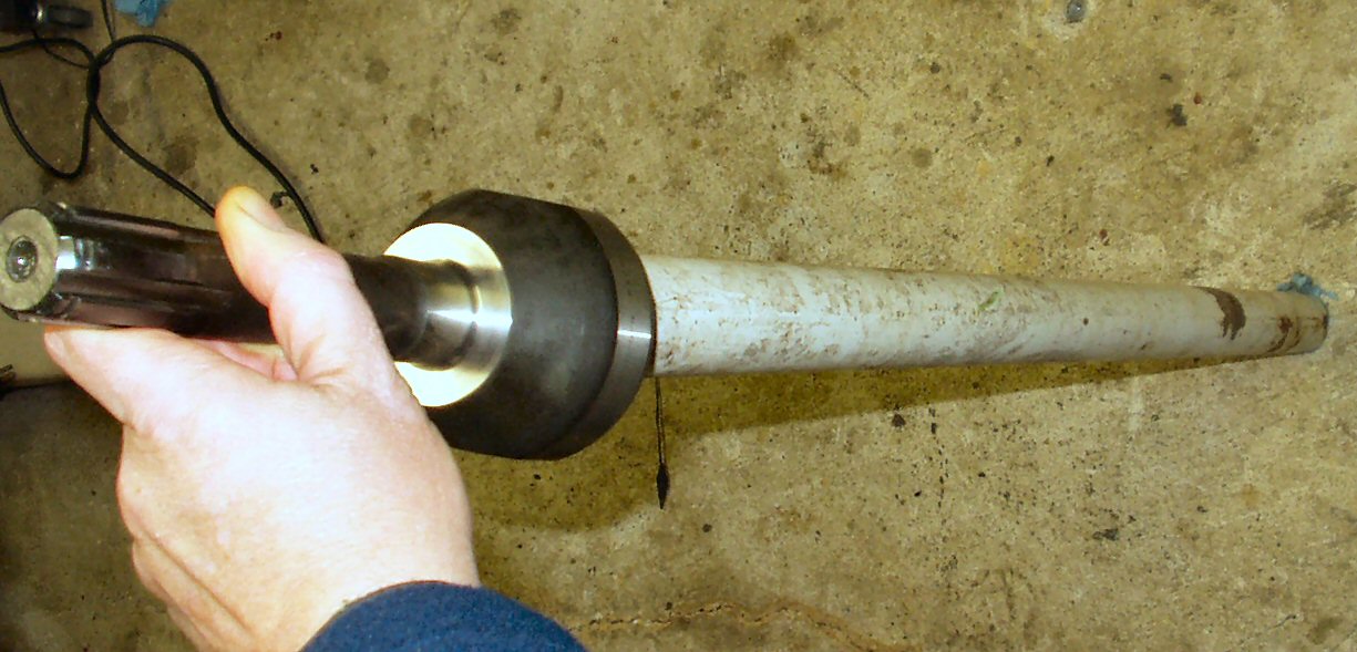
3' length of 1 1/2" pipe
To separate the Birfield from the inner axle.
Anti-seize
For all nuts and bolts that don't require thread locker
Multi-purpose grease
You will need at least 2 pounds of this for the Birfield's and all the Knuckle bearings.
Thread Locker
For Knuckle Stud bolts
Pipe Wrench or Channel Locks
To set tie rod length
8mm x 1.25 x 3" studs
You can cut the heads off of bolts for these. Makes putting spindle on much easier!


There are several prep steps that you can do to make the re-assembly go much smoother.

  1. The knuckle housing has 26 tapped holes in it. We are going to clean out each hole with a tap. Yeah , yeah 52 total holes to clean out. Get you mind out of the gutter... Believe me, with all the de-rusting, washing, wire wheeling and painting or powder coating there is crud down in those threads. Better to clean them out now, than to strip and break a bolt off in them later.
  2. You will need a 6mm x 1.0, a 8mm x 1.25, and a 12mm x 1.25 tap. You will also need a 12mm x 1.5 and a 12mm x 1.25 die to clean up the studs. (Some claim you should always replace the studs anyway.)
  3. Start with the 6mm holes on the back side of the knuckle. These are the ones that hold the Oil Seal Covers in place. Put some thread lube on the tap and carefully start it in the hole. If you feel resistance then back the tap out 1/2 turn and try again. If you feel resistance again then back the tap out completely, clean the threads and start again. The last thing you want is to break a tap off in a hole! Run the tap all the way to the bottom.
  4. Next up: The front 8mm holes that hold the spindle and backing plate on. Same as above.
  5. Then do the two steering stop holes with the 12mm x 1.25 tap.
  6. If you removed the top and bottom studs while taking the knuckle apart then use the 12mm x 1.5 tap to clean these out. Note! The studs have 12mm x 1.25mm threads one one end and 12mm x 1.5 threads on the other! The 1.5 threaded end goes into the knuckle and the 1.25 threaded end is for the nuts that hold the steering arm and bottom Knuckle bearing retainer in place. They are NOT swappable!
  7. Apply some Anti-seize to the 1.5 mm side of the knuckle studs and using two nuts back to back thread then into the knuckle housing. Tighten to 43 - 54 lb ft torque. Remove the nuts.
  8. Use the 12mm x 1.25 die to clean up the threads on all the studs and steering stop bolts.
  9. Install the steering stop bolts from the rear of the housing. Leave about 1/2 " sticking out for the lock nut. You will adjust this later. You want the 'head' to be pointed toward the 3rd member when installed. Install the lock nut on the front.
  10. Use a wire brush on a drill and clean the threads of all the bolts that will thread into the knuckle housing. If they look damaged then run a die across them. Anal? You bet! Never striped a bolt in my life that I had done this to when combined with cleaning out the tapped holes.
  11. While you have the wire brush out run it over the gasket faces front and rear of the housings. This will remove any over spray of paint or powder coating. Set the knuckles aside for now. Also run it over the knuckle bearing studs, inside the housing and anywhere else that needs it. Blow out the housing and all the screw holes with compressed air.
  12. Use some crocus cloth or some 1000 grit sand paper to remove the baking haze from the knuckle bearing studs and the housing.

Kunckles

Fig. 1

Knuckles Before Prepping


Birfield Prepping

Get on your latex gloves and clear off the work bench. Time to take the Birfield's apart to clean and inspect them! Of course if you are rich, then you will have bought a set of Long Fields or something similar, and can skip all this messy crap.

Breaking Axle Loose

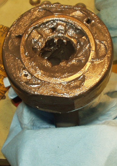
Fig. 2

Breaking Axle from Birfield

Birf Free

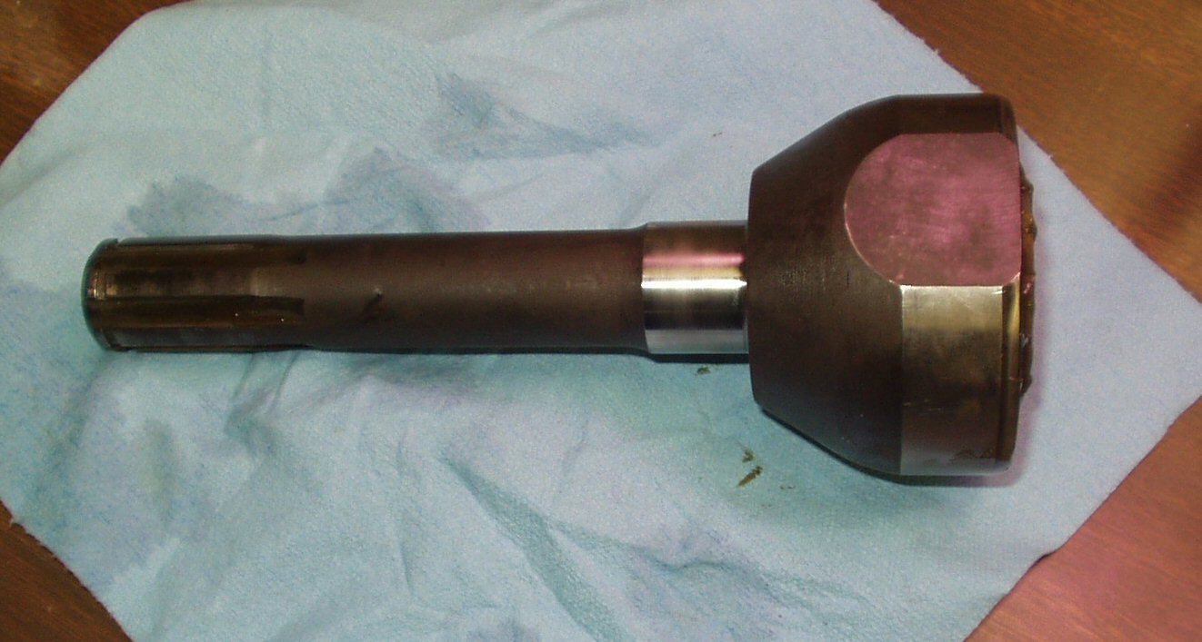
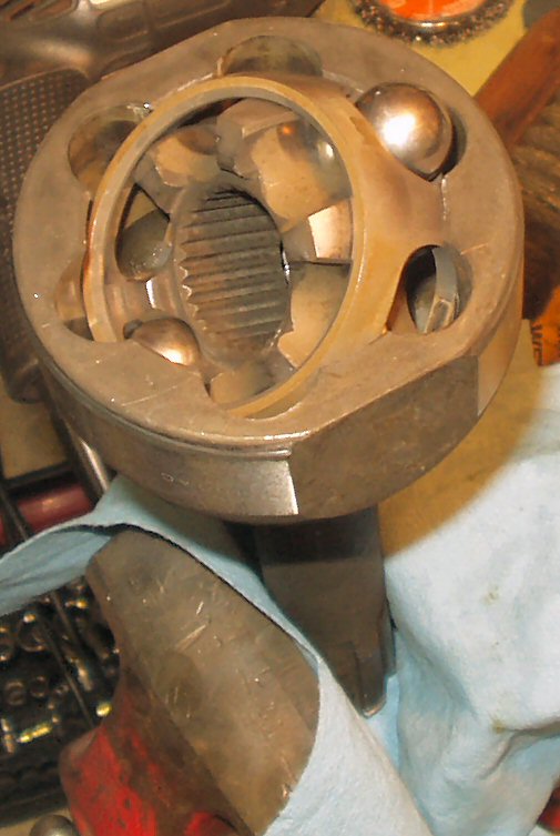
Fig. 3

Birfield Free
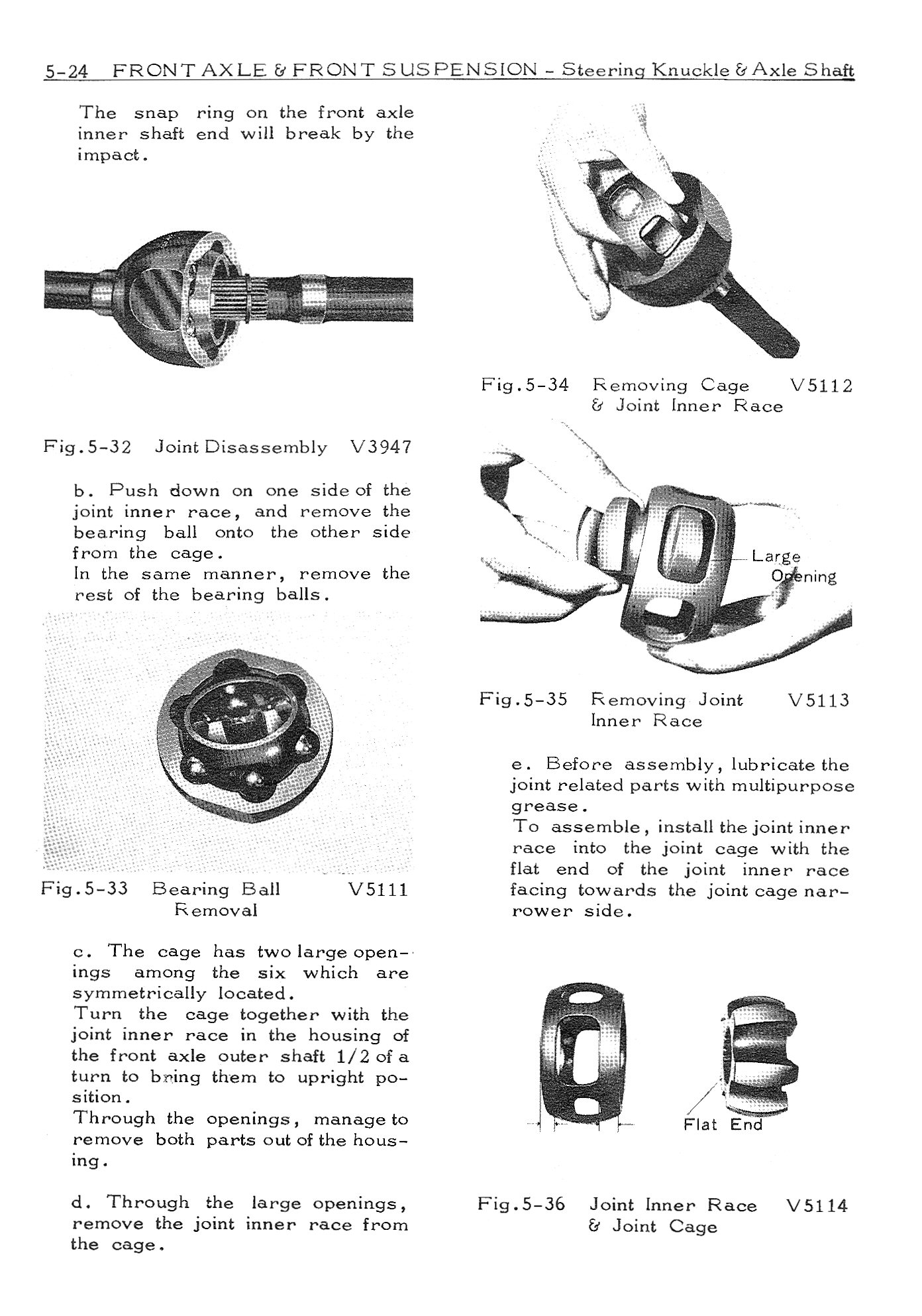
Birf Manual Page

Fig. 4

Manual Page

Degreased

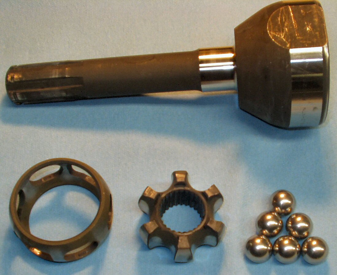
Fig. 5

Degreased and disassembled


  1. Work with only one Birfield at a time! The parts of each Birfield have worn to match each other.  You don't want to mix them up! I used a grease pencil to mark each one so I could also get them back into the same side.
  2. Clean off all the external grease from the Birfield.
  3. Lay down an old soft towel or some clean wrapping paper on the work bench. (Good use for that old Christmas wrapping paper) We don't want dirt to get in the Birfield's!
  4. Now get the 3' piece of pipe and stuff a big rag in one end. Slide the inner axle into the other so that the Birfield joint rests on the pipe. See Fig. 2.
  5. Raise the pipe about chest level and slam it STRAIGHT down on a hard surface like concrete. a big honking rock or an anvil if you have one. If you are lucky the inner axle should separate from the Birfield on the first try. If not repeat until it does. It took 4 times for mine to separate. What you just did was break the snap ring that holds the Birfield to the inner axle!
  6. Fig. 3 shows the now separate Birfield At this point you can start taking the Birfield apart. No tools needed! Clamp the birfield in a vice, bell end up.
  7. Refer to Fig. 4 which is a page straight from the Toyota manual and remove the balls, cage and race.
  8. Clean all parts thoroughly, wash in hot soapy water then dry thoroughly. See Fig. 5.

Manual Page 2

Fig. 6

Page 2

Race into Cage

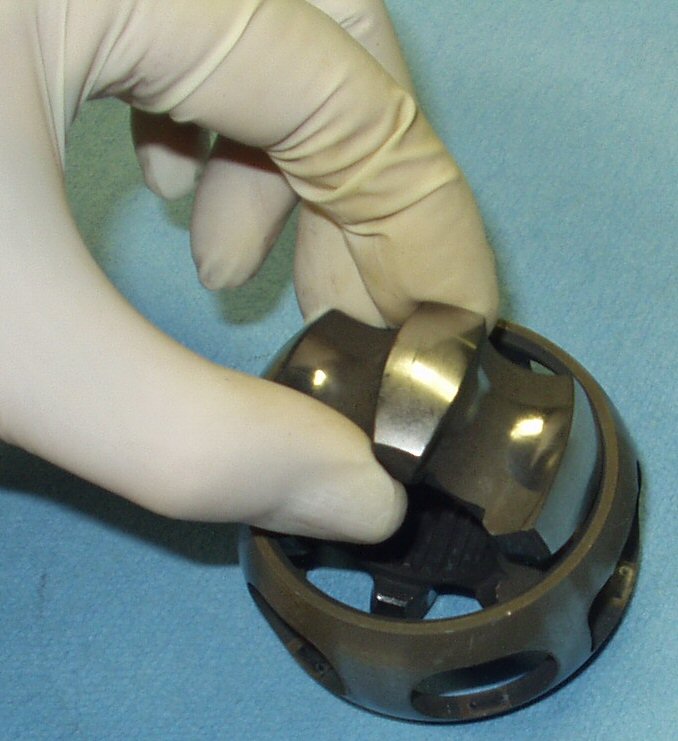
Fig. 7

Race Into Cage

Installing cage & race

Fig. 8

Aligning the race

Cage & Race In

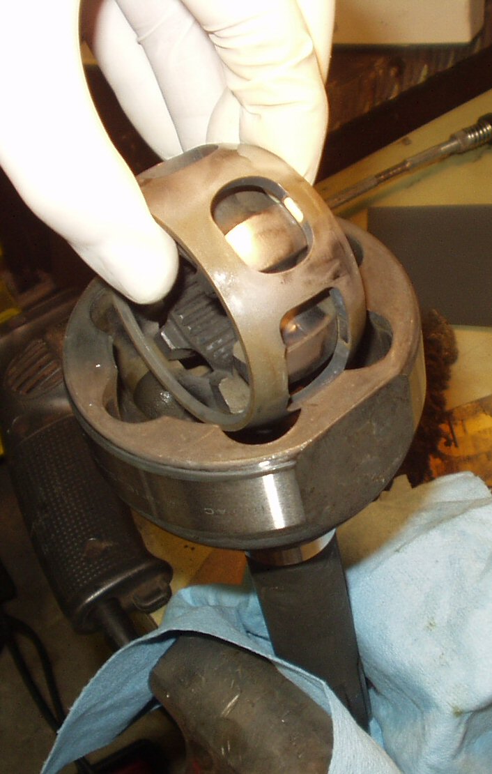
Fig. 9

Cage & Race In

  1. Figs. 6-9 show the reassembly process done dry with no grease. This is just to show you the way it goes together without the grease blocking the view. Do not assembly them dry then try to grease it later!
  2. Start the reassembly by thoroughly coating the inside of the bell with a thick coat of grease. Then coat the race, cage and your balls (the Birfield balls man! Geez!)

1st ball in

Fig. 10

1st Ball In


Push Ball Down

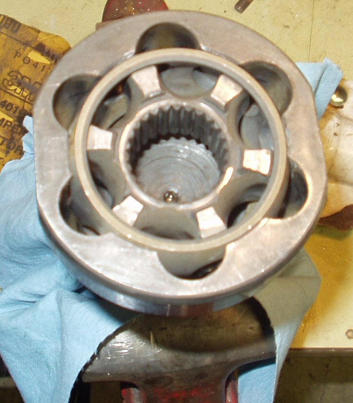
Fig. 11

Push ball down into place

Next Ball

Fig. 12

Second Ball

All Greased Up

Fig. 13

All Greased up


  1. Use Figs. 4and 6 and 10-13 to reassemble the Birfield's. The only thing to watch out for is the orientation of the race and cage. The manual pages show how it goes.
  2. Wrap the completed Birfs in plastic or paper to keep grit out of them until you actually re-install them in the knuckles.

Replacing the Seal Felts

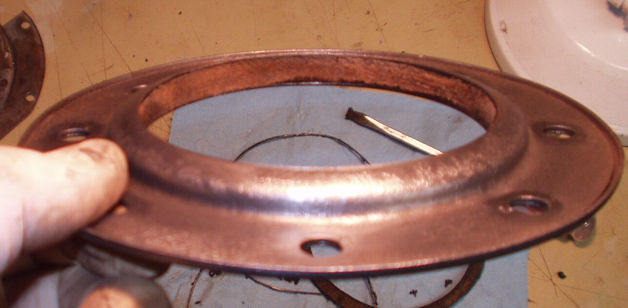
The early style oil seals have a replaceable felt inner ring. These will be included in your knuckle rebuild kit and they are pretty easy to install.

Felt Replacement

Old Felt

Fig. 14

Old Seal Felt

Removing Old Felt

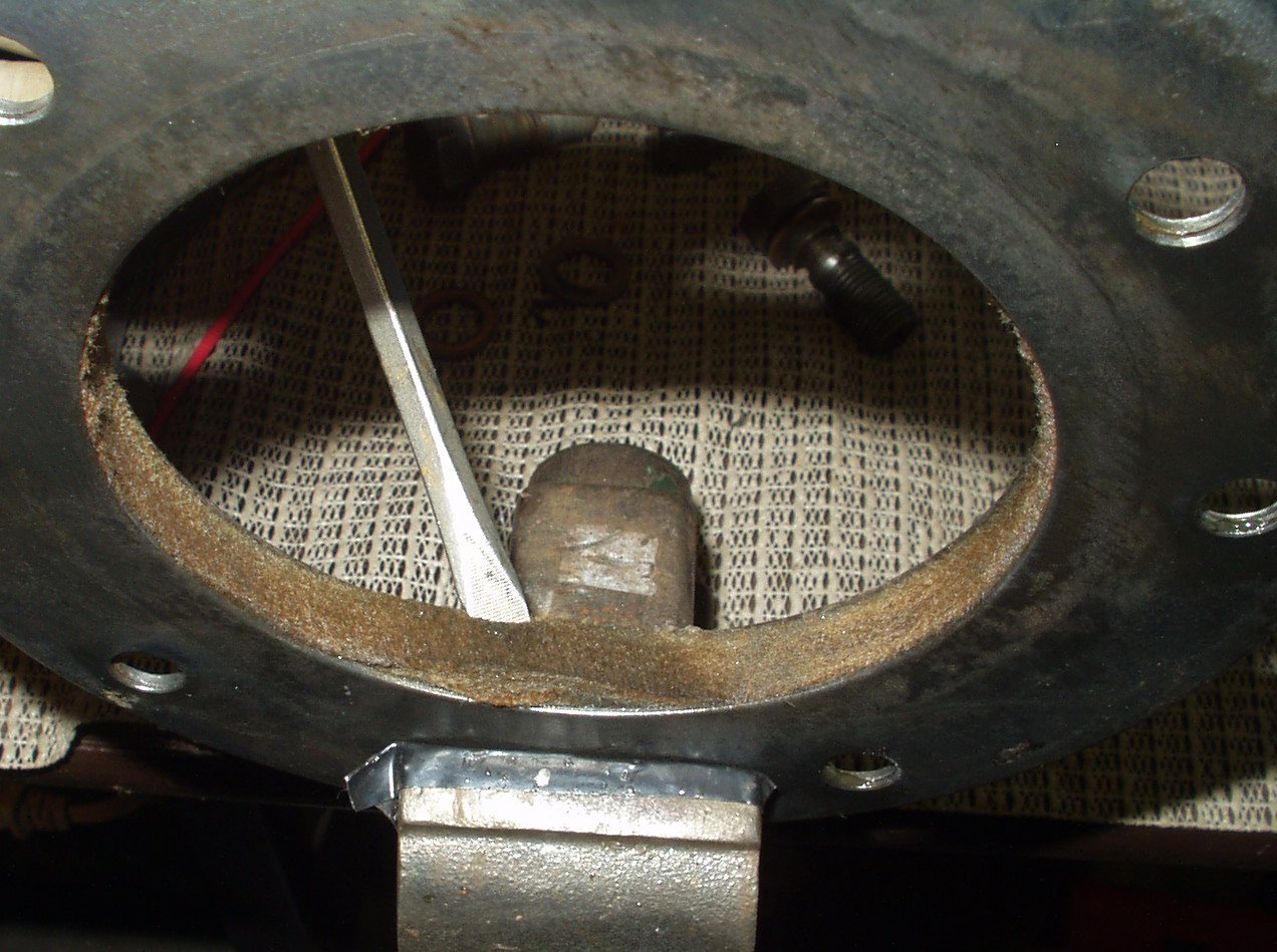
Fig. 15

Removing Old Felt


Felt and retaining Rings

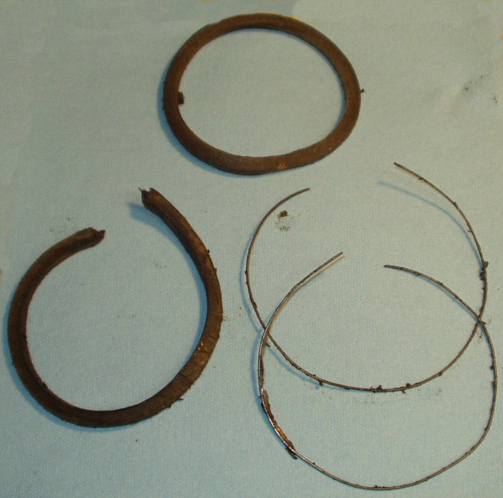
Fig. 16

Removed Felts and Wire Retaining Rings


Installed Felt

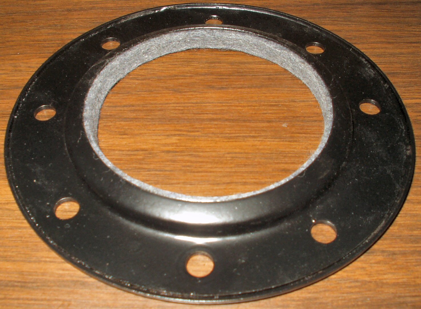
Fig. 17

Felt Installed

  1. Fig. 14 shows the old felt ring mounted in the seal. It wasn't in too bad a shape considering it was 33 years old!
  2. To remove the old felt, clamp it gently in a vice, and use a small screwdriver or other tool to pry it out. See Fig. 15.
  3. You may find wire retaining rings in yours as shown in Fig. 16. They were only in one of mine. It's strange but someone had cut one of the felt rings before they put it in! Maybe it was too big? Though I don't have a pic of it I remember there was a large gap in the felt and that side had leaked worse than the other.
  4. Clean out all the old gunk and grease from the inner part of the seal. If you are going to paint it now is the time.
  5. Installing the new felt may be a bit frustrating but it WILL go in WITHOUT cutting it! Use a pair of wide electricians pliers to compress the felt as you work your way around the ring. Stuff it in with a small, thin, straight blade screwdriver. Just keep working it in until it's all the way in. It may have a couple of wrinkles in it but after a bit they work themselves out. See Fig. 17 for the completed seal.

Next Up: Reassembly Page 2


Home

1971 Body/Chassis FSM

1971-74 F Engine FSM

Page Index

Hosted by Global Software, Inc.

©1998 - 2023 Mark C. Baker Web Designer

Please: No part of this web site may be used without express permission... email mbaker@globalsoftware-inc.com for permission.

www.globalsoftware-inc.com