All the bearings and races are the same for the knuckles
top to bottom and left to right so you don't have to worry about mixing them
up.
Coat the race and race seat in the housing with a thin film
of grease.
I used an old race and a large brass rod I have to drive
the new ones in. A large socket will also work or if your careful a brass
hammer. Drive them in evenly alternating one side to the other until they
seated. They make a distinctive sound when seated but you can also look through
the housing and see.
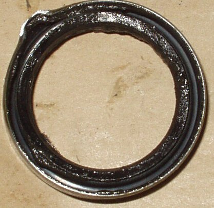
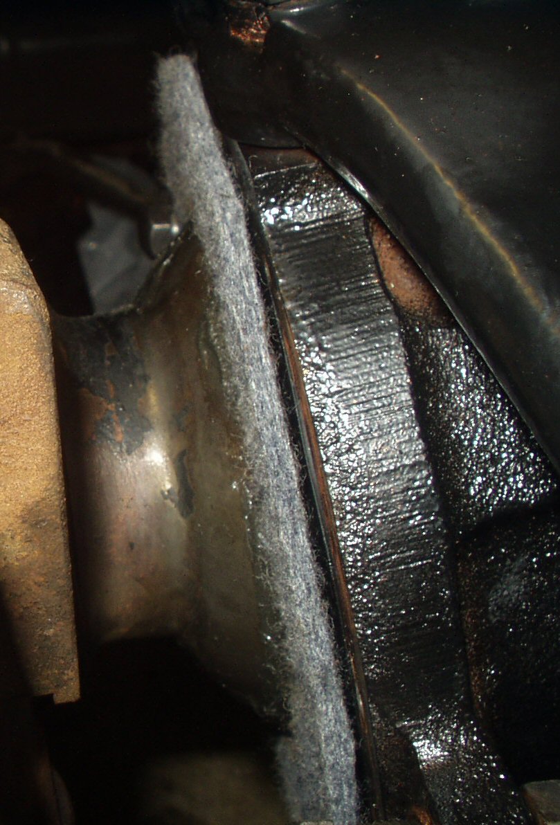
Install the axle seals the same way. I have a seal driver
I got from JC Whitney to drive them in but while doing the passenger side
I got in a hurry and messed up a new seal. I let it get crossways cause I
was too lazy to get out a light so I could see better. Grrrrrrr.. See Fig.
1. I had to order one from JT
Outfitters.
Final Assembly:Installing the Knuckles
Note: If your knuckles have been
worked on before or you are having problems with the axle seals failing quickly
allowing grease and diff oil to mix then you really need to buy or borrow a
knuckle alignment tool. Try this: Part #09634-60013. It is available thru OTC
@ 1-800-533-6127 cost $112.21.
This has been a long project! Some claim they can do this job
in a weekend but with all the cleaning up I had to do because of the failed
seals, total steering disassembly, the decision to de-rust all the parts, powder
coating and of course just learning how to do the job, this job has drug out
for several weeks!
Make sure you have the eight nuts, lock washers, and cone washers
ready to install.
Lets start by wiping down the knuckle ball with a clean rag.
Get both races clean.
Go ahead and pack the knuckle bearings with a good multi-purpose
grease and set aside.
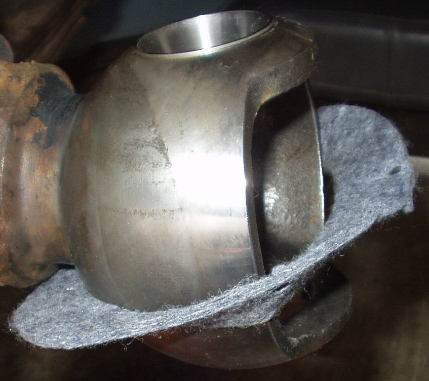
Get the gasket kit and locate the rubber ring and the large,thick,
knuckle shaped felt pieces. You'll also need the split metal rings you saved
from the tear down.
Fig. 2
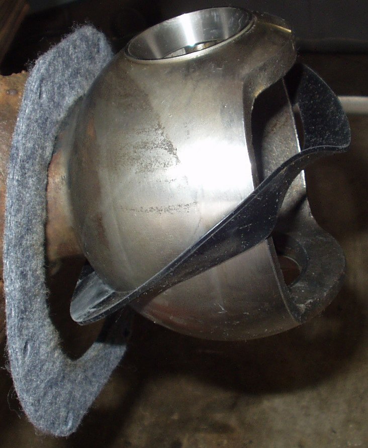
Fig. 3
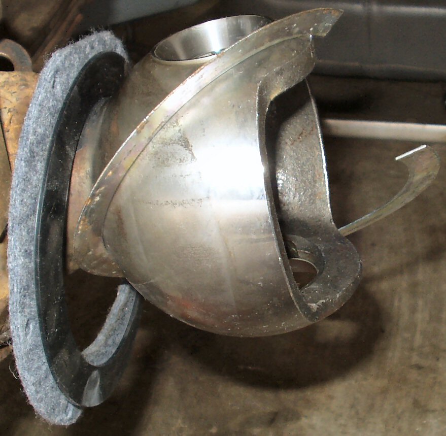
Fig. 4
Fig. 5
Install the felt by placing it as shown in Fig.
2 then work the top part over being careful not to tear it.
Install the rubber ring as shown in Fig.
3 then work the top part over the ball.
Install the split metal ring as shown in Fig.
4 then work the split part over being careful not to bend it.
See Fig. 5 for all the items
installed.
Place the knuckle housing on the work bench.
Grease the lower bearing retainer and place the lower bearing
retainer into the knuckle housing.
Coat all the cone washers with a good coat of anti-seize
and lay them and the lock washers and nuts out on a piece of paper in easy
reach. You may never have to get back in here, but, if you put the Anti-seize
on now, it will really aid in future removal. (Like when you break that Birfield
on the steep uphill section of the trail and have to take it apart to remove
it?)
Coat the lower studs of the knuckle housing with a good coat
of anti-seize.
Then place the bearing retainer over the studs and put the
cone washers, lock washer and nuts on. Only thread the nuts on just a bit,
you want the retainer to be loose.
Fig. 6
Fig. 7
Fig. 8
Fig. 9
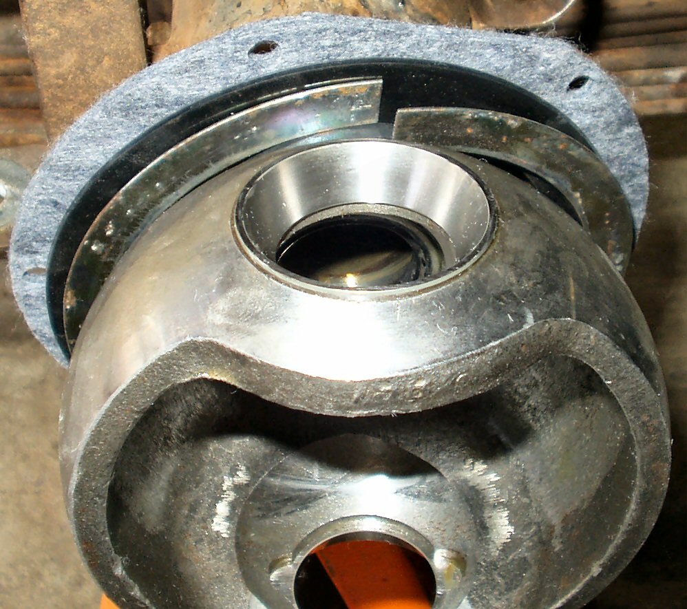
Coat the bearing races top and bottom, and the ball with
a good thick layer of grease. See Fig. 6.
Press the bottom bearing on to the bearing retainer stud
inside the knuckle housing.
Take the knuckle housing to the axle and referring to Fig.
7 tilt the knuckle housing as shown so the bottom bearing goes into
place first, then tilt the housing up so it goes over top of the top bearing.
Just let it sit there.
Coat the bottom of the top steering arm with grease. Slide
it over the knuckle studs then guide the bearing stud into the top bearing.
You will need to wiggle it around a bit. Don't try to force the stud through
the bearing all the way, just get it started. You will use the nuts to seat
the stud the rest of the way. See Fig. 8.
Install the rest of the cone washers, lock washers and nuts
finger tight.
Using the 17mm socket start tightening the top nuts in a
criss cross pattern. Stop after a turn or two and do the same to the bottom
nuts. Gradually tighten them all down working top to bottom to seat the studs
in the bearings.
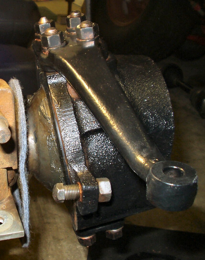
Get your torque wrench out and set it to 43-54 ft lbs torque.
Torque each nut in a criss cross pattern. You should feel a light drag now
when you turn the knuckle housing with your hand. See Fig.
9.
Measuring the Knuckle bearing Pre-Load
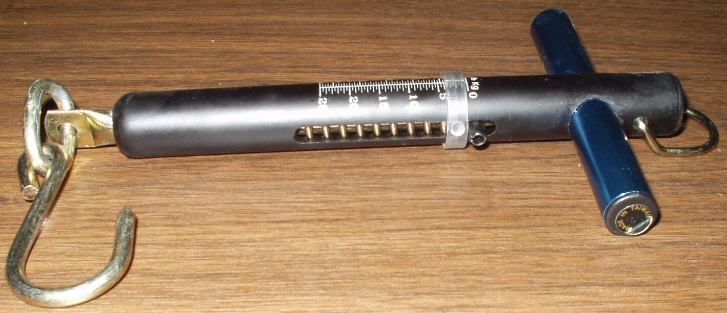
Fig. 10
Spring Scale
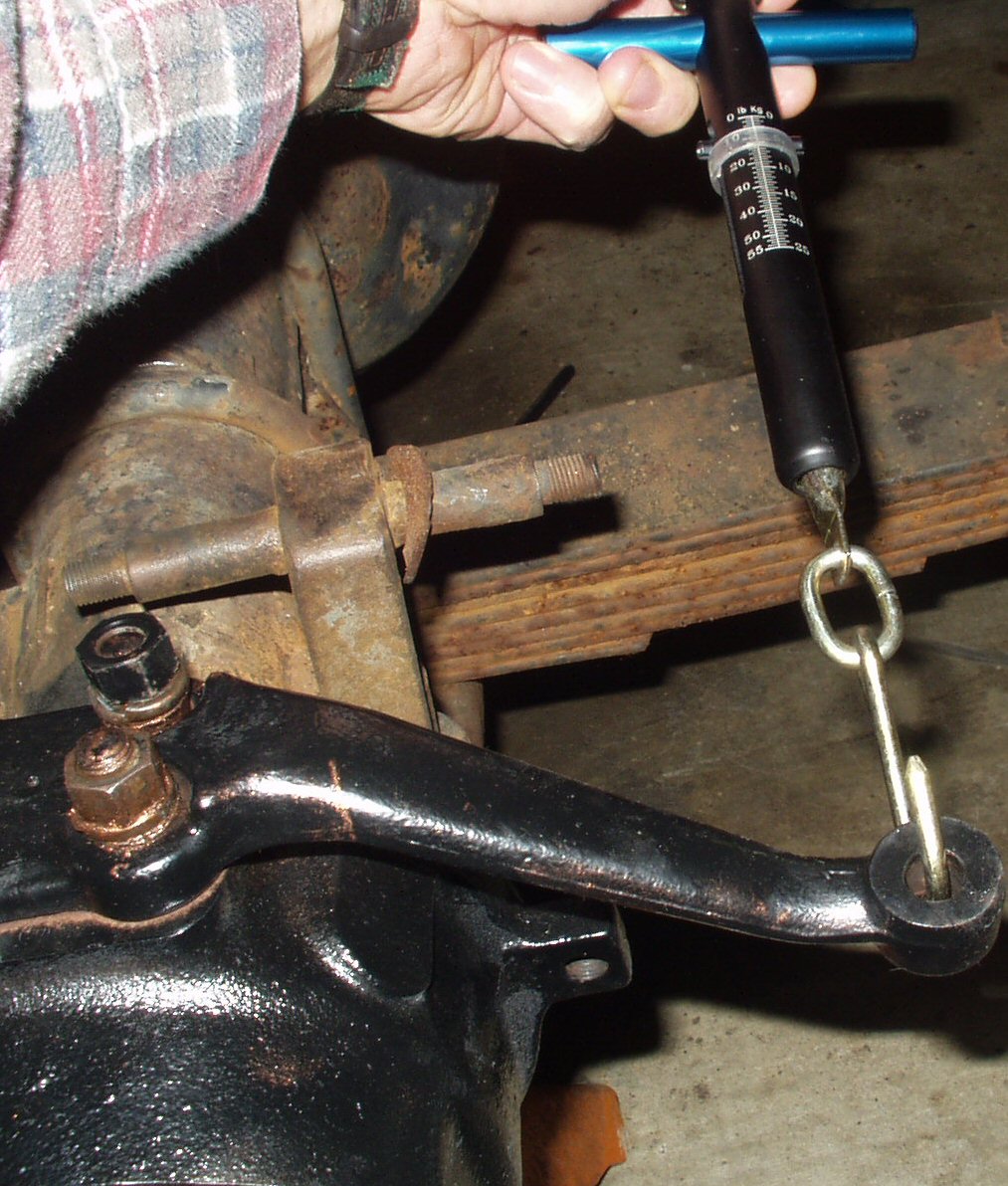
Fig. 11
Measuring the Pre-Load
This step in my opinion is optional. The reason I think this?
Unless you have the SST for this job you really can't correct it if it's wrong!
However just for peace of mind I bought a spring scale from Marlin for $9.95.
See Fig. 10.
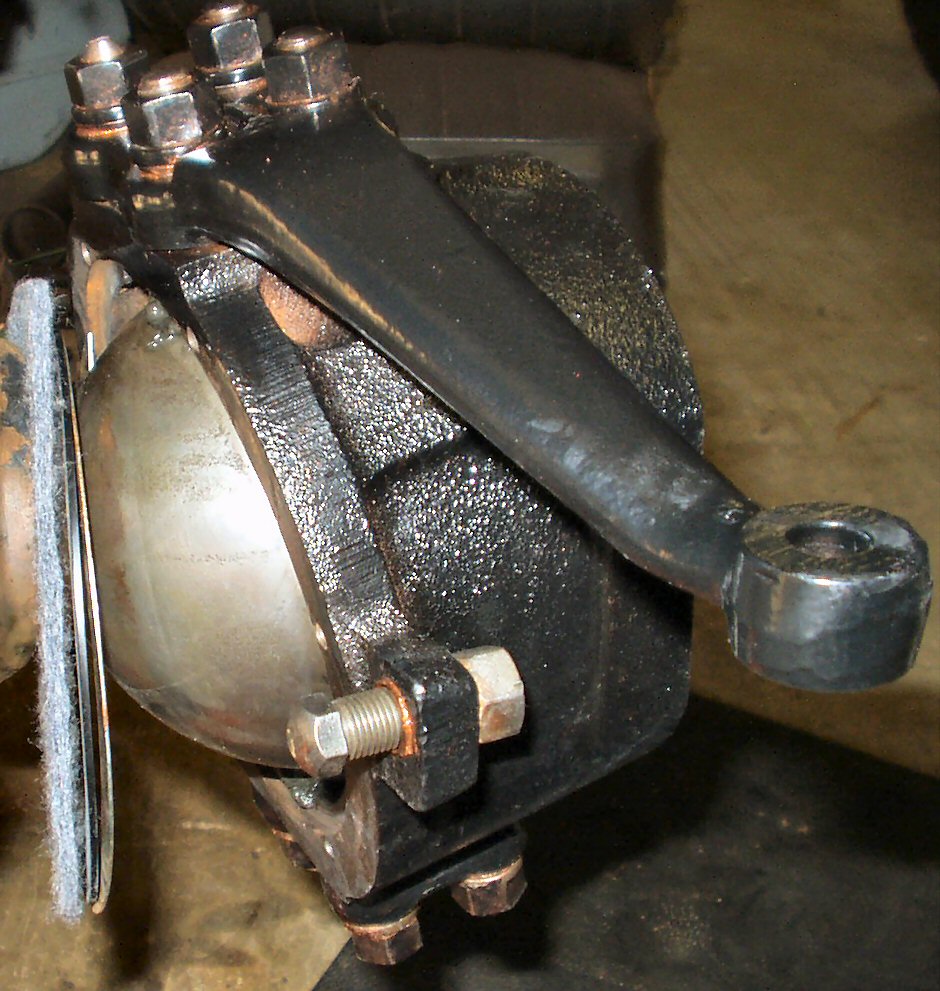
To measure the pre-load attach the spring scale as shown
in Fig. 11, center the knuckle then start steadily
pulling on the scale until it just starts to move. Read the scale at that
point. On my scale the white ring shows where the scale stopped so it's easy
to read it. The value should be 3.9 to 5.0 lbs. My driver side was 3.5 and
passenger was 4.5. Close enough for government work. :-)
Final Assembly:Rear Seals
Fig. 12
Installing Rubber Ring
Fig. 13
Felt in Place
Fig. 14
Seal Retainers
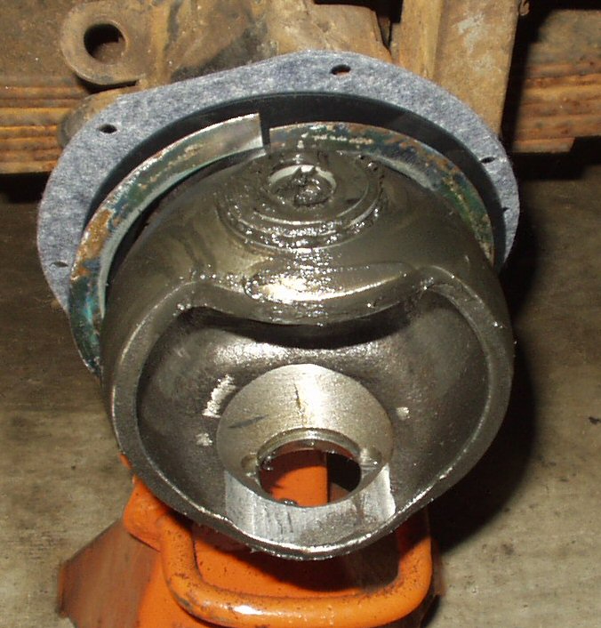
Press the metal ring into the cutout in the back of the knuckle.
Press the rubber ring in the cutout in the back of the knuckle
on top of the metal ring. See Fig. 12.
Press the felt into the same place but make sure the holes
are lined up. See Fig. 13.
Get the two seal retaining plates and the 8 6mm x 1.0 hex
bolts with washers. Place the top plate so that the curved lip on the bottom
points out.
Insert 4 bolts and finger tighten them. Repeat for the bottom
half retainer. Tighten the bolts to 4-6 ft lbs. See Fig.
14.
Final Assembly: Birfield/Axle
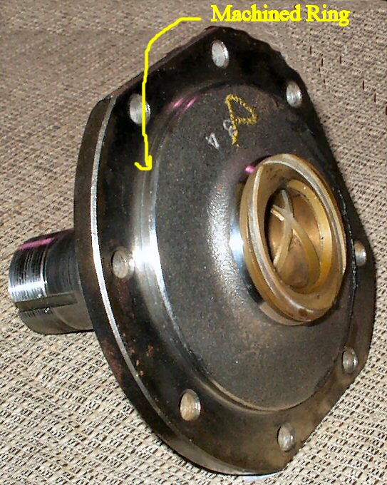
Fig. 15
Machined Ring
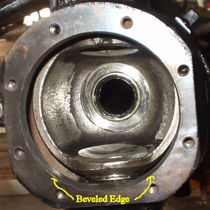
Fig. 16
Beveled Edge
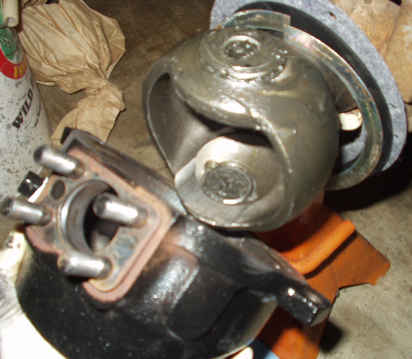
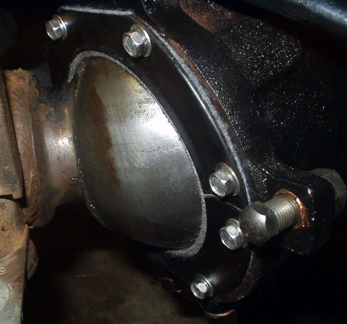
Before doing anything else dry fit the spindle
on to the knuckle housing to see if it aligns properly. The spindle has a machined
ring that fits into the front of the knuckle housing. See Fig.
15. The knuckle housing opening is beveled to make insertion easier.
See Fig. 16. It is a very tight fit as it is what
aligns the spindle with the knuckle. I had more problems with this that I can
tell you! I had already greased up the Birfield and axle, inserted them into
the housing and was trying to fit the spindle in place when I noticed there
was a 'gap' about 1/8" wide between the housing and the spindle. I incorrectly
assumed that my Marfield tack was in the wrong place and took the greasy axle
back out, ground out the weld and moved it back about 1/8". Put it all
back together and it still had the 1/8" gap. Hmmmm next I assumed that the
Birfield was not seated on the axle all the way and made a major error when
I attempted to hammer the end of the axle to drive it on further. (I used a
board over the end of the axle!) When that didn't gain me anything I again pulled
the Birfield/axle or let my say I triedto pull them.
Seems that the hammering had driven the inner axle into the side gears by riding
up on the Marfield tack thus firmly jamming it in place. When I tried to pull
the assembly out all that came out was the Birfield! I had a hell of a time
getting the inner axle out. So don't do that!
I finally realized that the Birfield/axle had
NOTHING to do with this. I left them out and tried to seat the spindle on the
housing. It would NOT go! WTF? I tried the passenger side and while it was a
bit tight it went right on. I looked for burrs on the the two mating parts and
could not find any. I also checked for powder coating that may have gotten into
the housing but it was clean. So I took a small round file and started taking
off a VERY small amount of material from the beveled area of the housing. After
just a couple of passes it finally fit. By now half the flipping day had passed.
Ok, now that you know what not to do lets continue.
Fig. 17
Birfield inserted
Fig. 18
In Place
Coat the inside of the Knuckle housing and ball with a thick
coat of grease.
Get the Birfield/Axle assembly. If you did
the Marfield Tack then insert the axle into the Birfield. Coat the outside
of the Birfield housing with grease.
Make sure the axle shaft is clean then use
some 90W oil to coat the axle shaft to make it slick, we don't want to tear
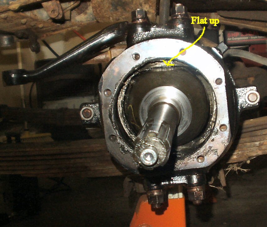
the axle seal! Coat the flat area where the seal will ride with grease.
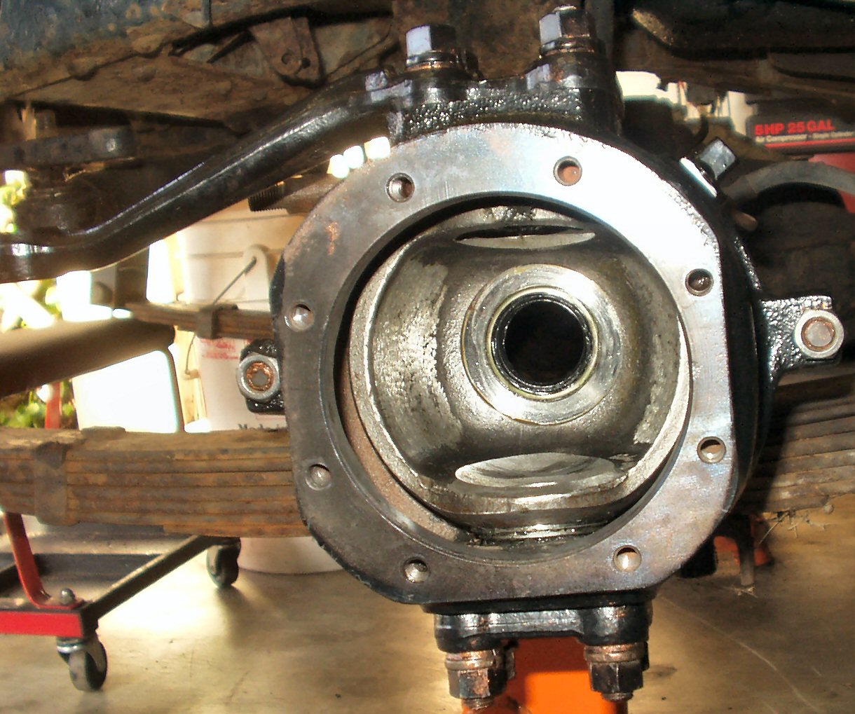
Turn the Birfield so that the flats of the
housing are pointing up and down. See Fig. 17.
Carefully place the end of the axle shaft through the axle seal and while
supporting it with one hand to keep it from dragging on the seal, slide it
in until it's about half way in and you are having trouble holding it. At
this point tilt the end you have up slightly so that the axle end is now hitting
the bottom of the axle tube. This puts the weigh on that instead of the seal.
Continue sliding it in.
When you feel the axle hit the side gears
you will need to push down on the end of the axle to raise the other end up
so it can enter the hole in the side gear. Yes this is pressing down on the
seal, it cannot be helped. This is one of those try it until it goes things.
You may have to rotate the front drive shaft a bit to align the splines. When
it goes in press it all the way in but DON'T hammer it in!
It took several tries for mine to go in,
don't get discouraged if you have a problem getting it in. See Fig.
18.