Repairing the FJ40 Fenders
Updated! 10-9-14 (Page Still Under Construction)
I'll start off saying this right now: If you have the money, just buy the whole damn fender! What I'm about to show you I did was not worth the effort for the result gained! If however you are on a strict budget like me then this will work.
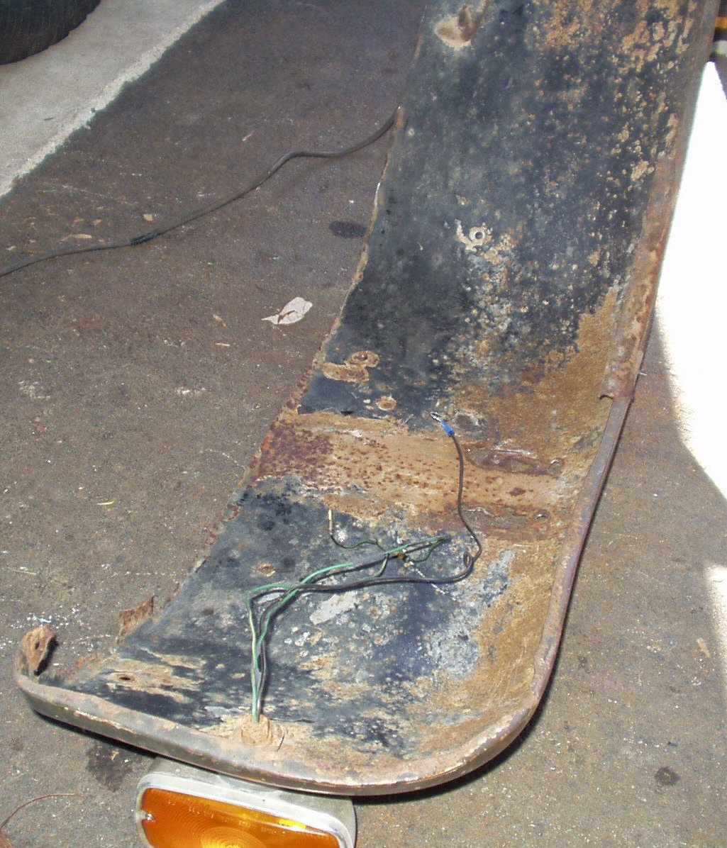
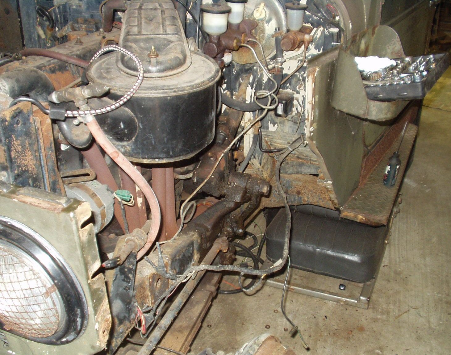
Fig. 1 Inner Fender Rust |
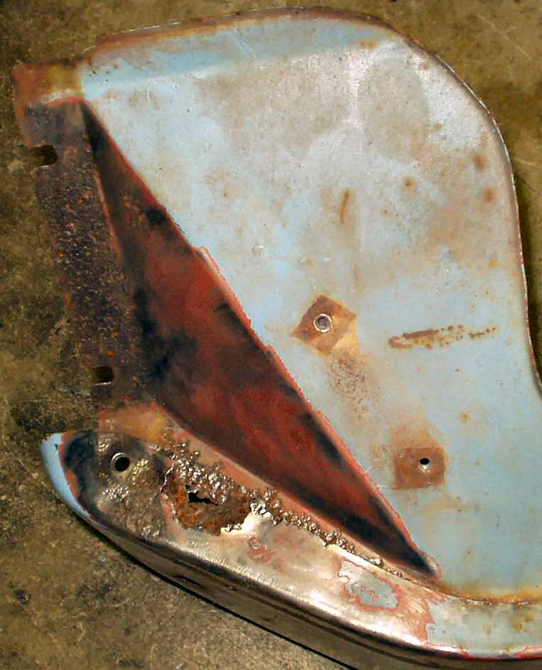
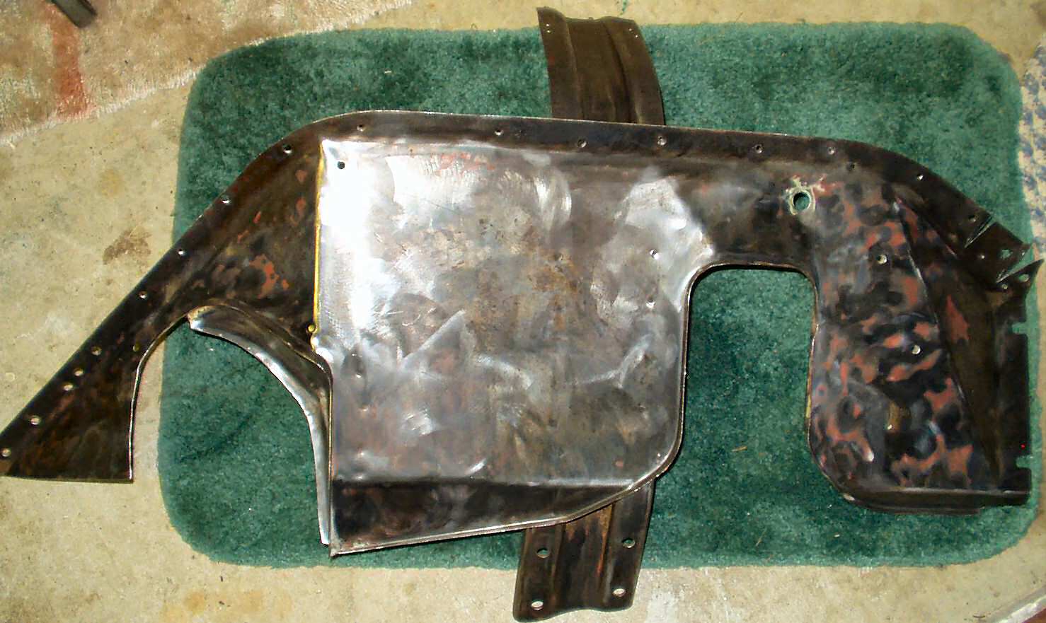
Fig. 2 Drivers Fender |
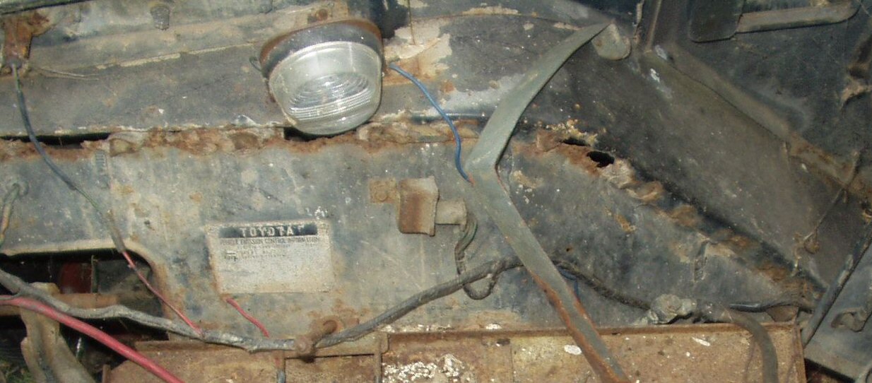
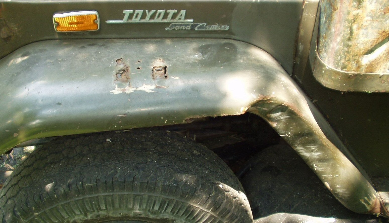
Rust and damage
My FJ's fenders were rusted badly along the inner seams and everywhere else for that matter. Not to mention a bit of tree damage courtesy of my brother. See Fig. 1-2. I knew that once I got it on the road that if I drove it in the rain it would soak the engine compartment. I shopped around and just could not afford the price of new fenders. I asked the list about used ones but if someone had them they were using them! Eventually I got a hell of a deal on a set of inner fenders from a friend in Colorado. I was out there on vacation last fall and picked them up while coming home. I figured that when I did the water pump I would have to drop the front bib anyway and that was half the battle of getting the fenders off right? Hah! Will I ever learn that on a 34 year old FJ40 there is NOTHING easy or goes as planned?
Removing the Passenger Fender
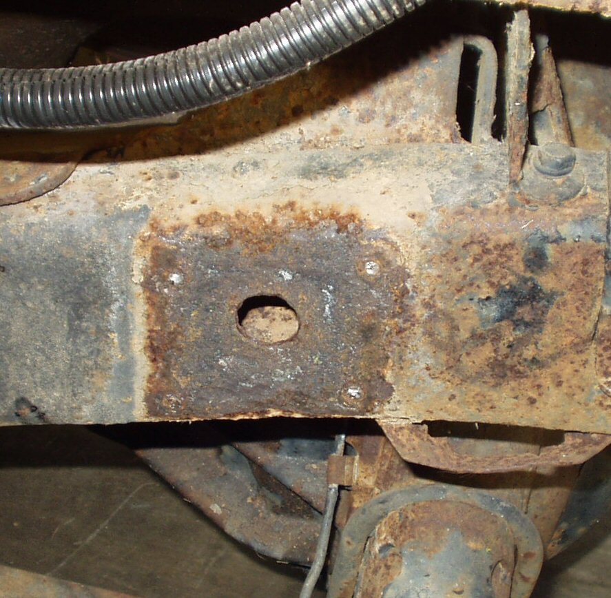
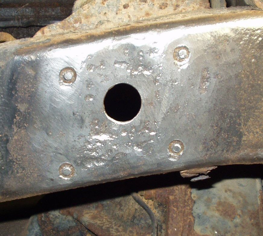
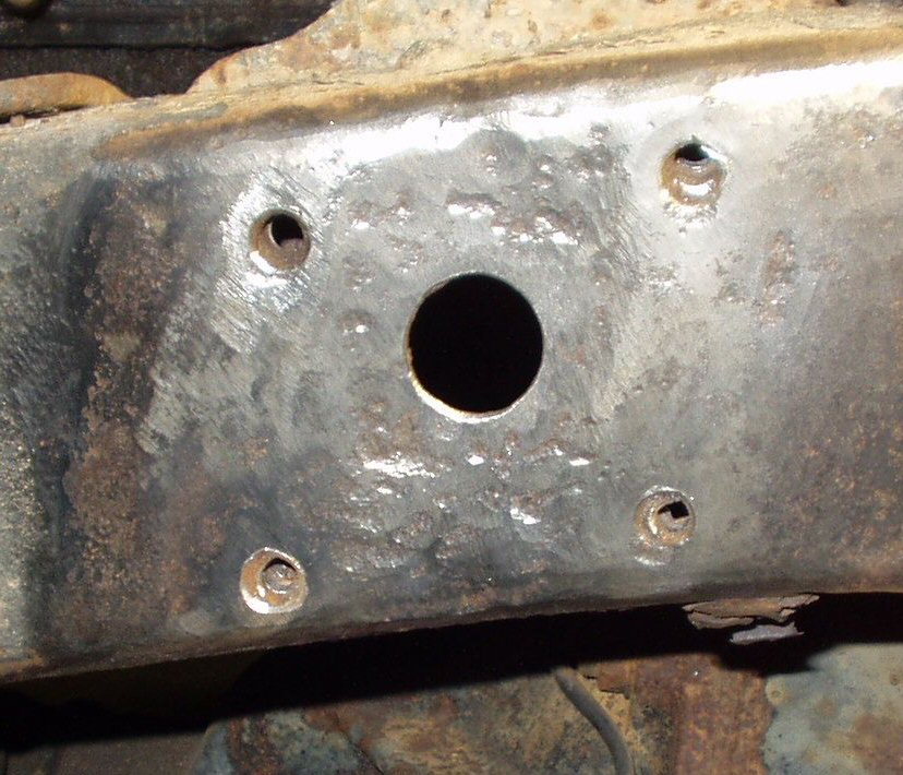
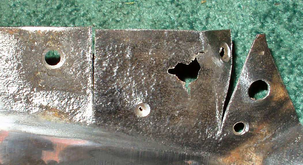
I started by soaking all the bolts I could find holding the fenders in place with Liquid Wrench the night before I actually started. This did not help much, I still broke just about every damn 10mm bolt I tried! 34 year old hardware in the rust belt just won't loosen, it breaks. I had better luck with the captured nuts, I only broke one of those. Next up was the bolts holding the fender support to the frame. I heated them, beat them, soaked them in Liquid Wrench, and proceeded to break every damn one of them! What I thought I could do in a matter of minutes took the better part of a morning. After getting the fender off I ground down the area where the fender support had trapped a lot of dirt and caused some extensive corrosion. I then drilled out the broken bolts and tapped them to 8mm x 1.25. See Fig. 3-6.
Fig. 3 Fender Removed |
Fig. 4 Broken Bolts |
Fig. 5 Ready to Drill |
Fig. 6 Three Drilled |
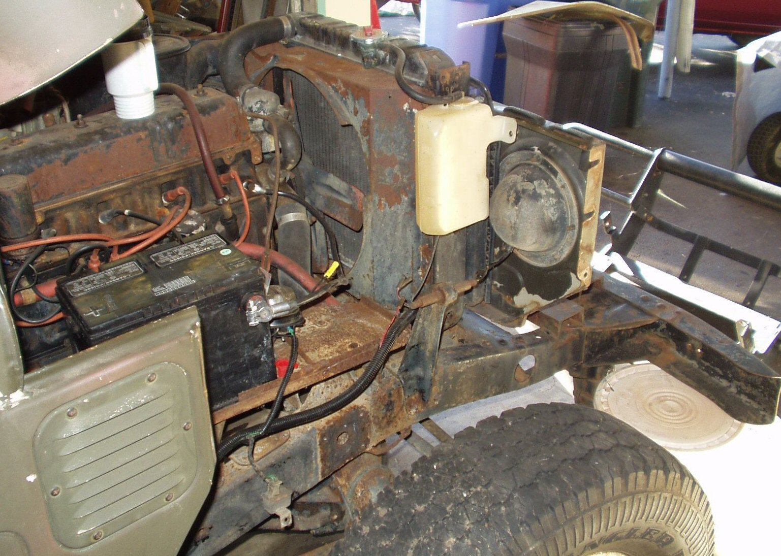
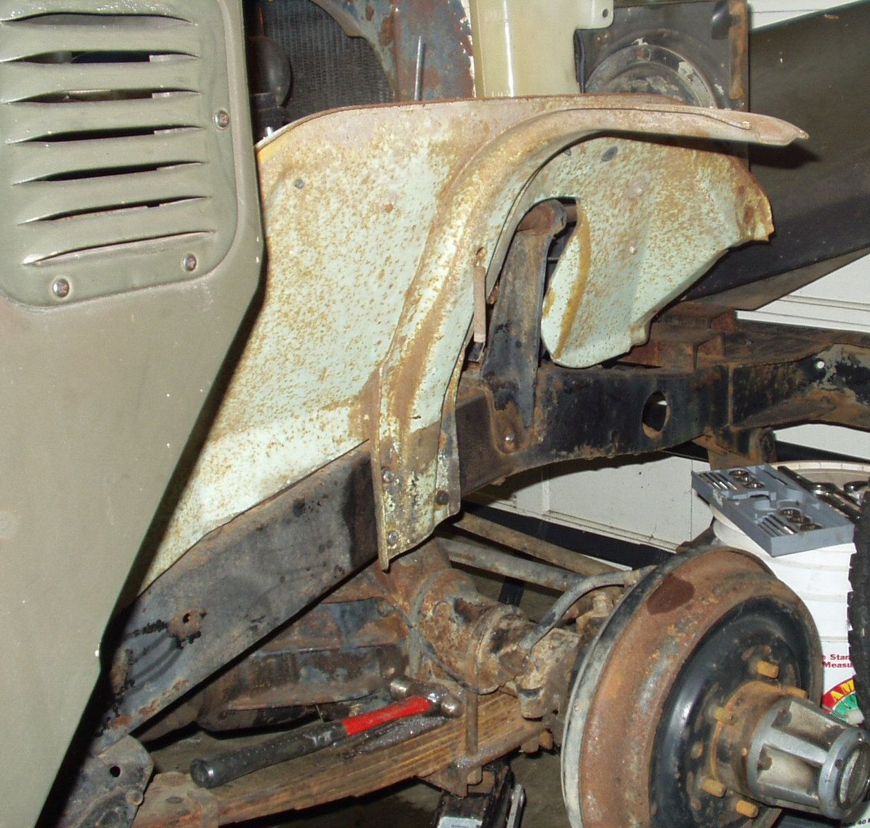
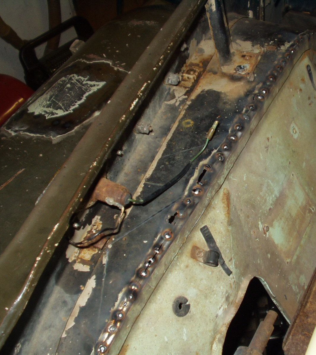
Now that I had the fender off I addressed how I was going to fix it. I started by mounting the inner fender I had to the frame. See Fig. 7. This allowed me to see what I needed to do to the rusted out fender to make it fit the 'new' inner. I started by drilling out the spot welds that held the fender brace to the fender. This wasn't too hard on the top as there were no metal left! After getting the support off I used a cut-off wheel to cut the inner fender off along the spot welded seam. See Fig. 8. I then ground down the edge flush with the fender top.
Fig. 7 Inner Mounted |
Fig. 8 Inner Cut Off |
Fig. 9 Patch Cut Out |
Fig. 10 Patch Tacked |
Fig. 11 Patch In |
Fig. 12 Finished! |
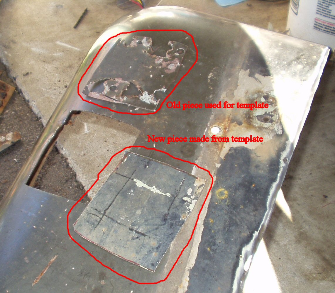
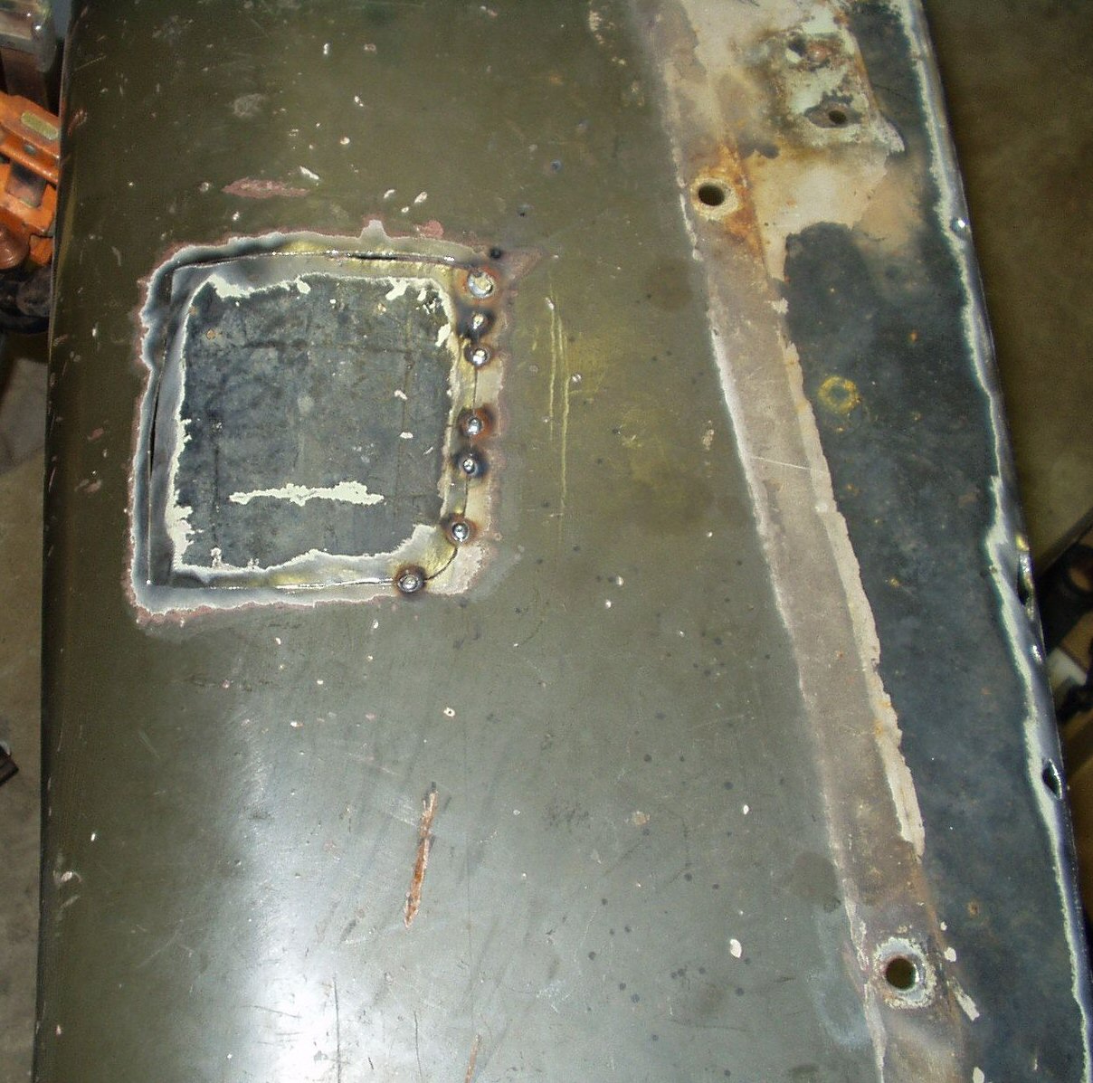
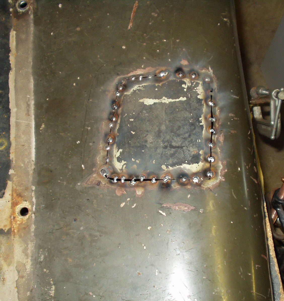
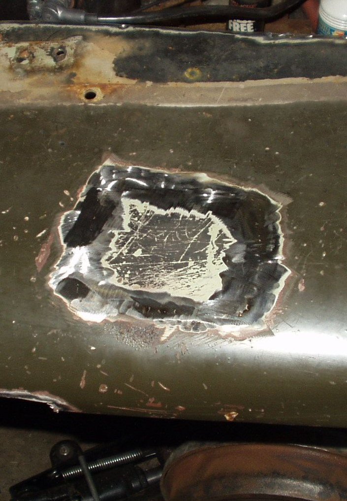
Next I used a jig saw to cut out the rusted area on top of the fender. I used the cut out piece as a template and cut a patch from the old inner fender. See Fig. 9. In Figs. 10-12 I tacked it in place, welded it in and ground it smooth.
Fig. 13 Welding together |
Fig. 14 Driver side removed |
Fig. 15 Driver Fender |
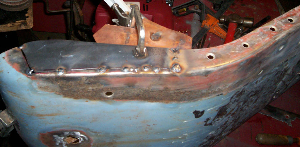
Getting the inner and outer fender to align with the body and the bib was an absolute pain in the ass! This was not helped by the fact my body mounts are toast. Well I did the best I could with what I had. In Fig. 13 I'm tacking the two together. I'll fill in the gaps later. remove it and sand blast the whole thing, use seam sealer on the weld seam, and then paint it. Fig. 14 and 15 show me starting on the drivers side. As of 11-29-2005 I'm into a lot of work on that side and have not finished the inner fender replacement. I will post the final results for this later after finishing the steering and knuckle rebuild
Update! 10-10-06
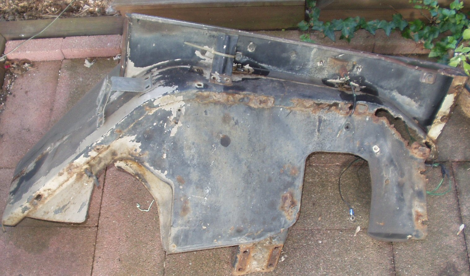
After working on so many other aspects of the truck I finally got back around to working on the front fenders. I looked at what I had done with the repair on the passenger side above and while it worked I was just not happy with the amount of rust on it and the fact it did not line up perfectly. So when a pair of fenders from a club member was offered to me for $75 I took them up on it. They are off a 1969. See Fig. 16-18. The drivers side needs just a bit of replacement metal work but the other one is in excellent condition and they fit my 2/71 perfectly!
Fig. 16 Drivers Side Worst Place |
Fig. 17 Second Worst |
Fig. 18 Underside |
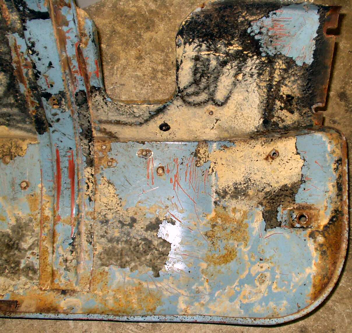
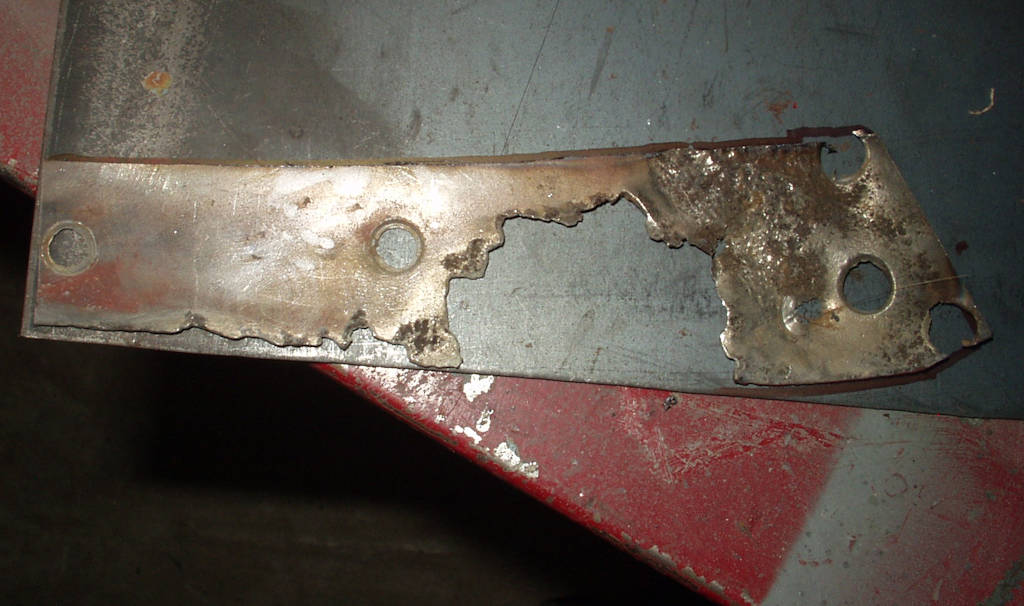
I started by examining the drivers side fender. It had more rust and damage than I thought so I decided to separate the inner form the outer fender and replace the inner with one I had gotten to fix the original fender. (Confused yet?)
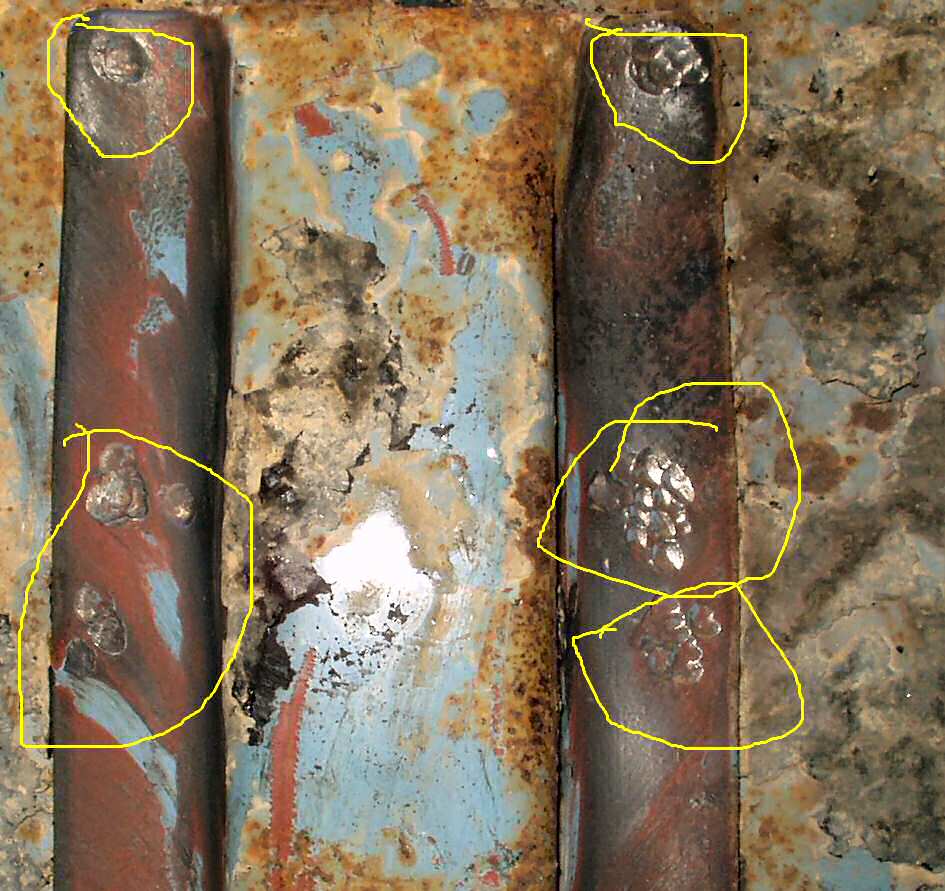
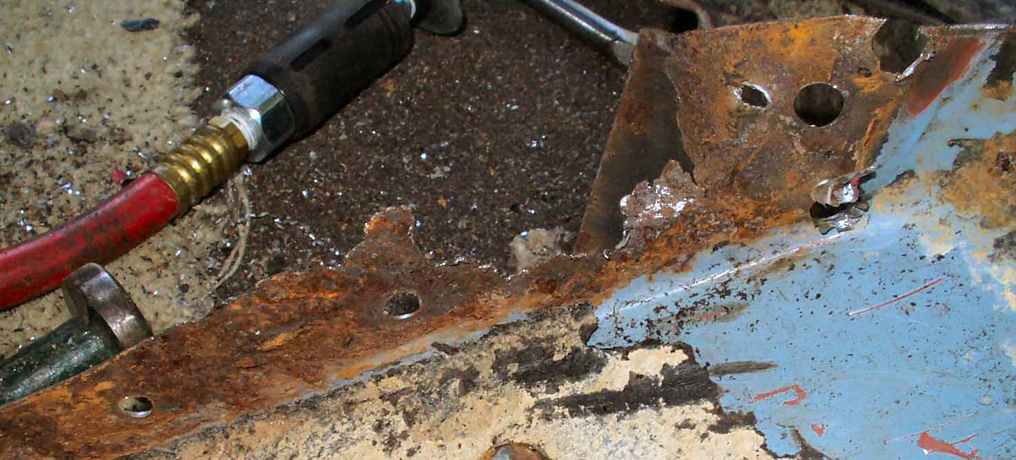
I first drilled out the spot welds holding the inner fender to the outer fender then the ones holding the outer fender to the support brace. See Fig. 19-20. There was a lot of rust between the two, but only a couple of places on the outer fender will need a small metal patchs put in place. See Fig. 21-22. The very top where it was spot welded to the brace was pretty thin and tore out on me when I used the air chisel to try to force the spot welds apart. Yeah I was a little more aggressive than I should have been! Just another patch to make and weld in...
Fig. 19 Removing Spot Welds I |
Fig. 20 Removing Spot Welds II |
Fig. 21 Small repair area |
Fig. 22 Thin metal! |
Next I dug up the inner fender I had and dunked it into the de-rust tank for a couple of days. Once it was out I used a wire brush to remove the rest of the paint, primer and rust. I will have a small area to patch on this also. It's the same place as the outer fender. Go figure...
Fig. 23 De-rusted Inner |
Fig. 24 Another Repair Area |
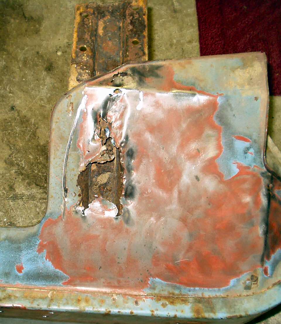
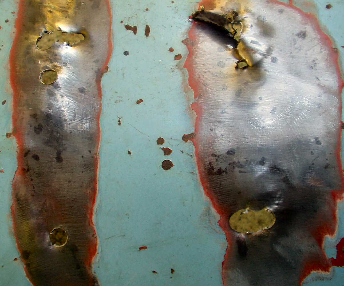
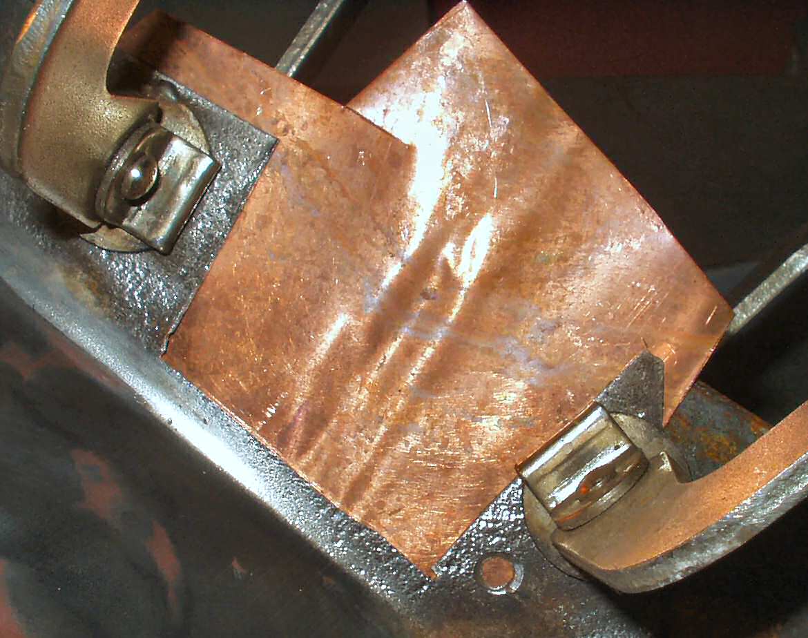
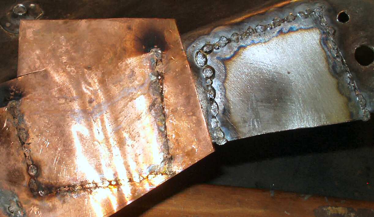
Here is a trick I picked up off the web. Clamp a thin sheet of copper under a small patch using a heavy straight piece of angle iron or something similiar. The angle iron will help keep the pieces straight and aligned. The weld will not stick to the copper and will act as a heat sink to prevent warping small panels.
Fig. 25 Copper Backing Plate |
Fig. 26 Results of Plate |
I proceeded to repair the rest of the inner fender, then started on the outer fender.
Update! 10-9-14
Yes, it has been 8 years since I last updated this page! You know the story, I moved, built a house, lost my father, lost my business partner, took over my day company as president, and while doing all that, I was building wiring harnesses and selling parts. Didn't leave a whole lot of time for working on !Oy... Any way, I will pick up where I left off.
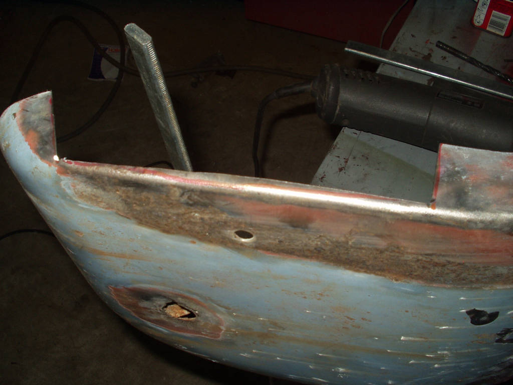
Fig. 27 shows the outer drivers fender and the repair in progress on that area that always rusts through. Cut out rust, make a patch panel, weld it in and grind it down. Repeat till finished!
Fig. 27 Rust cut out |
Fig. 28 Making Patch |
Fig. 29 Patch Welding |
Fig. 30 Ground Down |
Fig. 31 Patching the top |

The top of the fender had to have two patch panels, one for the top and one for where the turn signal mounts. I welded up the small patch panel and just filled in the two remaining holes with weld. Next up was the turn signal mount was rusted out. I drilled out the spot welds for the turn signal post bracket and then cut out the rust and made a small patch panel. I welded that in, and then welded the bracket back in.
Fig. 32 Removing the bracket |
Fig. 33 Bracket Removed |
Fig. 34 Cut out rust |
Fig. 35 Weld in Patch |
Fig. 36 Bracket Welded Back |


I had to straighten the fender in a couple of places. This involved putting the inner fender back on the truck and laying the fender on top while using clamps to hold it all together. I was taking measurements from the other side to ensure everything was aligned and matching.
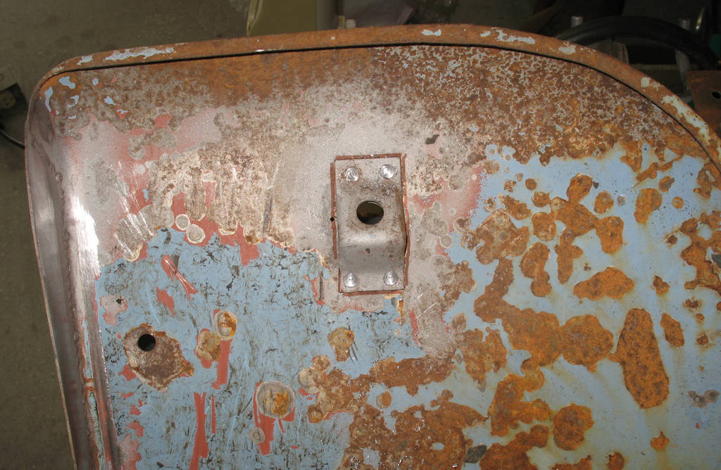
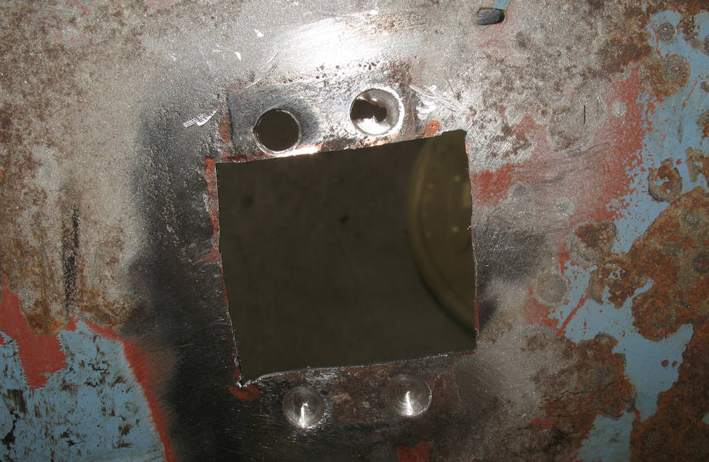
It was at this time I discovered that the inner fender was going to have to be trimmed to accomodate the mini-truck power steering box... Grr...... Turns out the inner fender has this "shield" spot welded to it. It's purpose was to protect the manual steering box from rocks and mud. Since the mini-truck power steering sits further back, this shield has to be removed, the inner panel trimmed to allow for the new box position, new lips bent where the cut was made, and finally the shield has to be modified to fit the new trimmed panel.
Fig. 36 Shield spot welds drilled, Cut lines for clearance marked
|
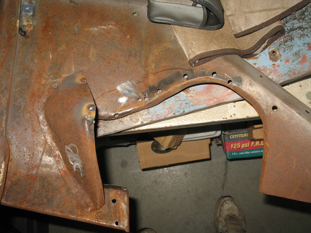
Fig. 37 Test fitting |
Fig. 38 Lip Cuts |
Fig. 39 Lips bent and welded up |

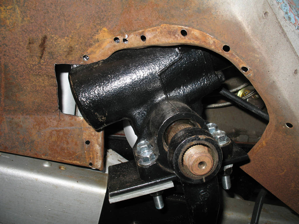
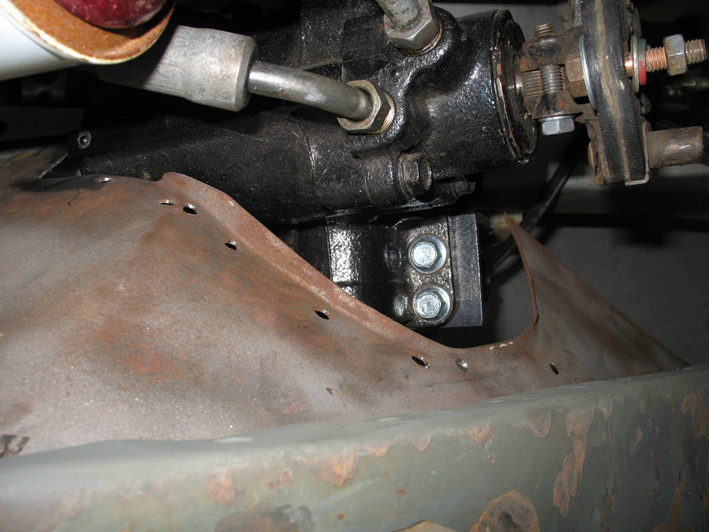
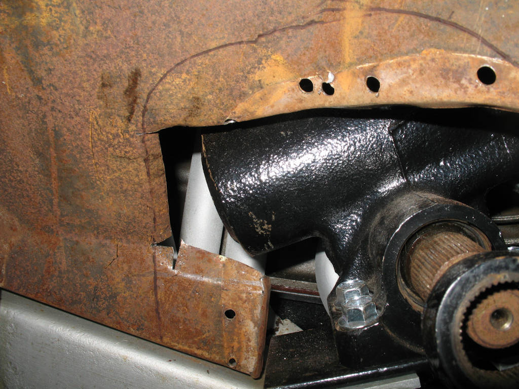

Fig. 36 shows the sheild spot welds drill out and the cut lines for the steering box clearance marked. I actually took out too much but it does make installation easier. After getting the shield off and the clearance cut made (See Fig. 37) I made the cuts for making the strengthening lips like OEM, then used a pair of wide jawed pliers to make the bends. See Fig 38. Next I welded the corners filling in where needed, then used a flap wheel to smooth everything out. I think it turned out pretty good! See Fig 39.
Fig. 40 Test Fitting Modified Shield |
Fig. 41
|
Fig. 42
|
Fig. 43
|
I decided to see if I could get the shield to fit after making the lips. This is a complicated piece! I ended up cutting about a third off one end, then forming it with a body hammer on my anvil to the shape shown in Fig. 40.
.