To open gap in rod ends and to remove the drag link end
screw. (Used as large screwdriver)
Tools needed for the following jobs
Replacing the 5 Tie Rods Ends
There are two ways to do this job: One is to replace the tie
rod ends one at a time and the other is to replace them all at once.
If your truck is a daily driver and you don't have a large block
of time to devote to this job then replace them one at a time as you can and
drive it in between. On the other hand if you are doing a restoration, or maybe
like me, a knuckle/brake/steering rebuild then remove all the rods (Drag,Relay
and steering) with tie rods attached at once and work on them off the truck.
What follows is a description of the latter.
Months before considering this project you started soaking
all the tie rod ends, castle nuts, and pitman arm with Liquid Wrench or Kroil,
or PB Blaster or Ed's Red. You did right? Of course
not. Get up and do it NOW! I'll wait. Refer to Fig.
1.
Remove the crud from all the tie rod castle nuts then pull
the cotter pins.
Use your 14mm wrench or socket and loosen the castle nuts.
Do not remove them all the way. They will help protect the threads when you
commence to beating on them.
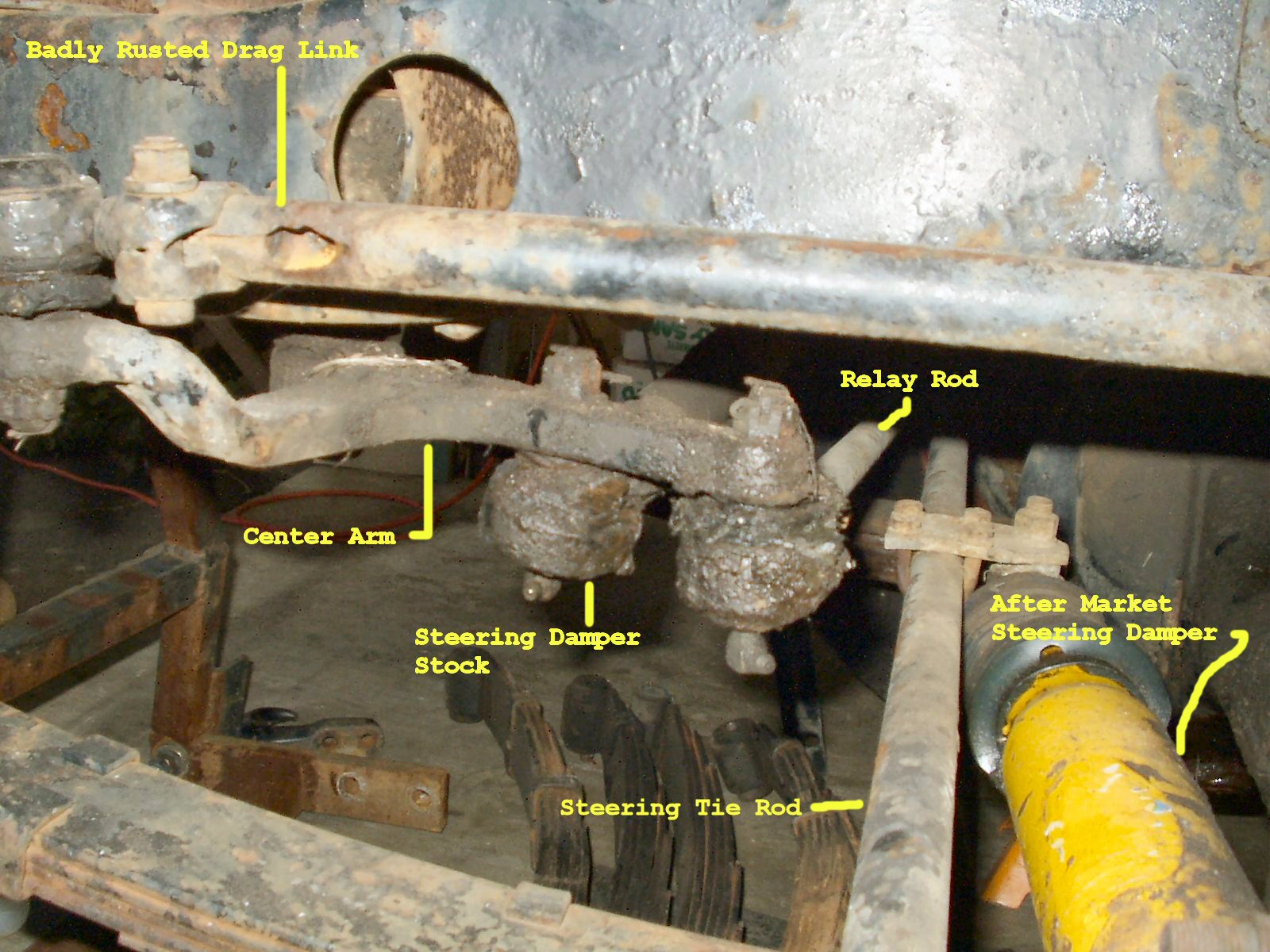
Using what ever tools you have, pickle fork, hydraulic puller
or BFH release the tie rod end from the Drag Link that's connected to the
center arm. See Fig. 1. Also release the stock
steering damper and relay rod from the center arm. An effective method is
to hit the SIDE of the arm holding the tie rod end with the BFH. This almost
always works if done several times. Don't be afraid to whale the tar out of
it! Just don't miss!
Center the steering box by turning
the steering wheel all the way to the left then while counting the revolutions,
all the way to the right. (Mine was 5) Now rotate the wheel back to the left
exactly 1/2 the number of revolutions you counted. (Mine was 2 1/2) Using
a punch making matching marks on the pitman arm and steering box housing.
You will use these to put the arm back where it was later.
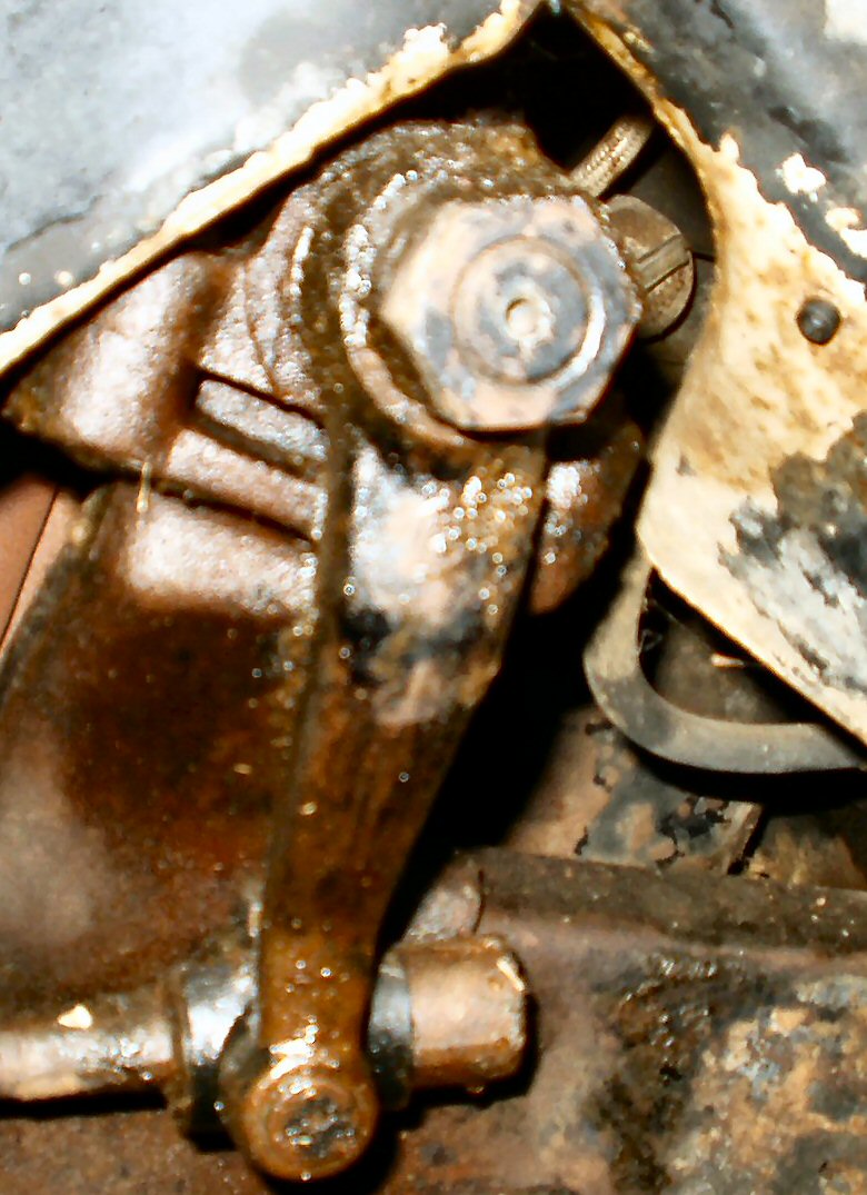
Now remove the steering box pitman arm. See Fig.
2. You will need a STRONG 2 or 3 jaw puller for this. a BFH to beat
on the side of the arm as you tighten the puller and possibly a propane torch
and a voodoo priestess. (The priestess is a last resort for hexing the damn
thing off!) Folks have told many horror stories about breaking cheap pullers
and knuckles trying to get this part off.
As you tighten the puller give the sides and top of the
pitman arm a couple of solid whacks with a BFH. This is what usually causes
it to pop off. Take your time these things have been on for 34 years, they
won't come off in an instant. As a last resort use heat on the pitman arm.
Remember that if you heat it up too much you will destroy the seal in the
box! Set the Drag Link with every thing attached aside for later disassembly.
Now release the tie rod ends from each steering arm.
Next disconnect the non-stock steering damper from the axle
mount if so equipped. You can now remove the whole mess of rods out from under
to truck to continue working on it. See Fig. 3.
Remove the clamp bolts that secure the tie rod ends. Use
a large screwdriver to pry them open a bit so they will slide.
Remove the non-stock steering damper from the steering rod.
You might want to make a note of how far from the end it was bolted so you
can put it back in the same place. I'm not putting mine back so I just removed
it.
Separate the two rods by releasing tie rod end holding the
relay rod and the steering rod together.
I highly recommend that you now de-rust these parts. Click
here for the page about this process. If
yours are as corroded as mine were, you will make this part of the job MUCH
easier! The rod ends can be very difficult to remove when they are rusted.
If you decide to not de-rust then here are some tips to help
remove the rod ends. First use a wire brush to remove as much rust as possible.
Use a propane torch with Mapp gas to heat the ends where
the threads are. Don't heat too much, you just want to break the rust bond.
While still hot clamp the rod in a vice. Get a BFH and a large chisel. Place
the chisel in the gap in the rod at the very end. A couple of sharp blows
will open up the gap a microscopic hair, (New tech term.) to allow your favorite
penetrating oil to get in.
Clamp the rod end tightly in a vice. Get the largest pipe
wrench you own. Mine is 2 1/2 feet! Put the pipe wrench on the rod just above
the gap. Start trying to turn it. Yes you are going to chew up the rod when
you do this. Can't be helped. Remember! Some of the rod ends are threaded
backwards or more properly they have LEFT HAND threads. On my truck
here are the locations and which threads they had. Note that
the relay rod can be mounted either way so yours may be backwards from
this.
Location
Thread Direction
Drag Link: End that connects to
Center Arm
Left
Drag Link: End that goes to Pitman
Arm
Right
Relay Rod: End that connects to
Center Arm
Left
Relay Rod: End that connects to
Steering tie rod
Right
Steering Tie Rod:End that connects
to passenger side steering arm.
Left
Steering Tie Rod:End that connects
to drivers side steering arm.
Right
Work the rod back and forth while continuing to put penetrating
oil on it. When it's loose enough, start taking it off. It it gets hard again
then reverse direction, put some more penetrating oil on it, and keep working
it. You don't want to strip these threads!
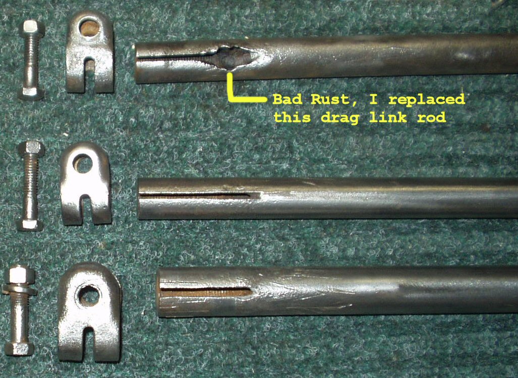
Repeat this for all the rods ends including the Drag Link
with it's tie rod end and drag link end.
Fig. 4
Cleaned Rods
Fig. 5
Rod Ends Installed and Adjusted to length
Once apart clean the gunk out of the threads. A perfect tool
for this is a Dremel tool with a small wire wheel. See Fig.
4 for cleaned rods and clamps ready to paint.
If you are going to paint these, now is the time. Do NOT
get paint in the threads!!! (Note: I put the rod ends in then painted
them.) I powder coated the clamps then primed and painted the rods.
Remove the rod ends if you put them in for painting. Use
the anti-seize and coat the internal threads of the rods and the external
threads of the rod ends.
Before threading in the rod ends put the rod clamps back
on! DON'T FORGET! (I did, twice!)
Assemble the ends to the two rods. Refer to page 6-25
in the slide show link above and set the steering tie rod and relay rod lengths.
The steering rod length should be set to 32.56" center of rod end to
center of rod end. Set the relay rod 47.44" center of rod end to center
of rod end.When you put all this back together don't forget to have a front
end alignment done! These settings are just ball park! Set the Drag Link length
to 33.66" From center of the rod end to center of where the pitman arm
ball mounts into the drag link end.
Slide the clamps to the ends of the rods, turn them so the
gap is aligned with the slit in the rod (bolt is 90 degrees to slit).
Apply some anti-seize to the clamp bolt threads and tighten them down. Do
this for all the clamps.
Note that the relay rod ends have one rod end that has a
longer shaft on it. This rod end goes into the hole in the steering tie rod
due to it's extra thickness.
Put the rods back under the truck. Coat the rod end threads
and shafts and the tapered holes in the steering arms and center arm with
anti-seize. Insert the ends and thread the castle nuts on them. Tighten them
down then insert the new cotter pins.
Give each new rod end a couple of hits with the grease gun.