- To make this job so much easier remove the drivers side fender. Curse loudly when all the bolts break off.
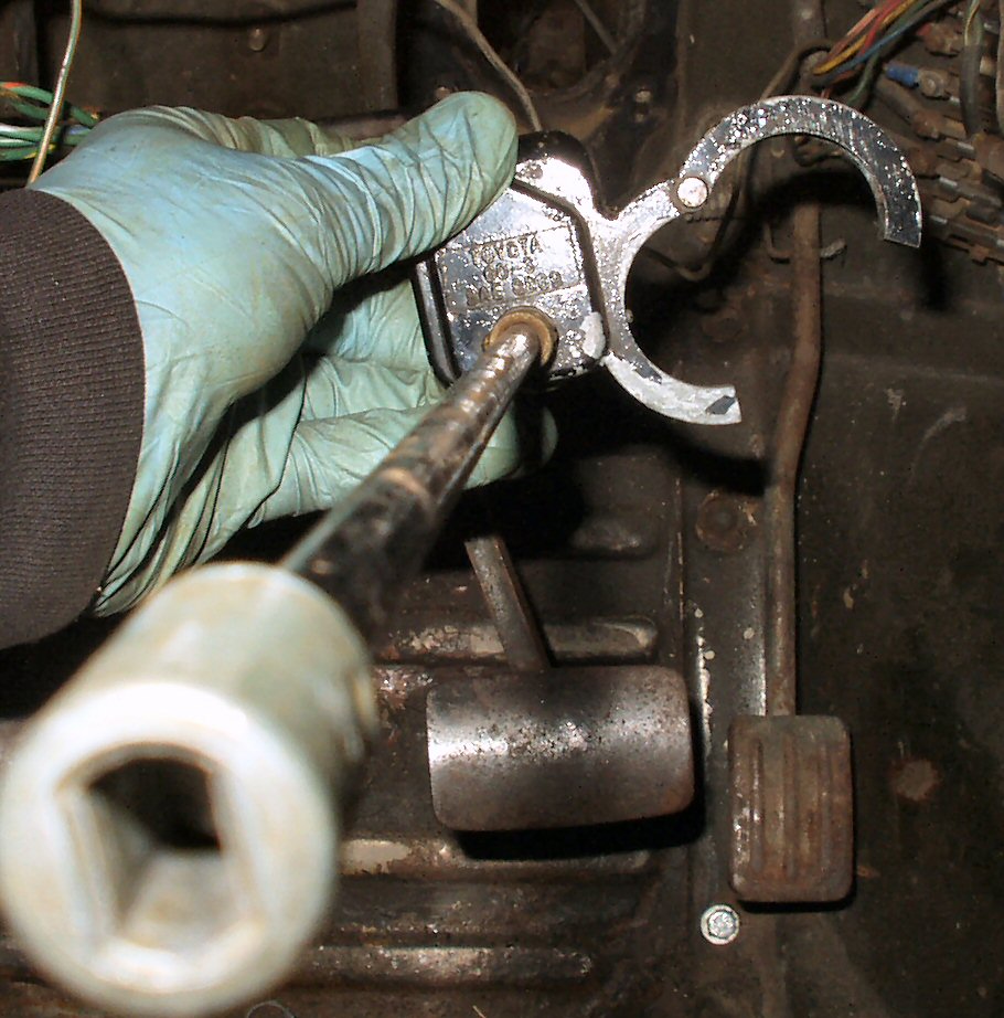
- Remove the pitman arm . Refer to Removing Pitman section. Curse extra loudly when it refuses to budge and then you break your puller.
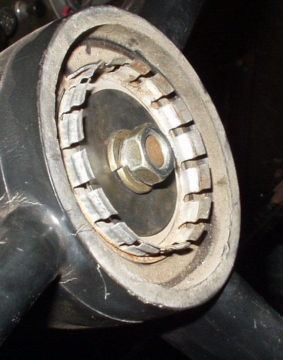
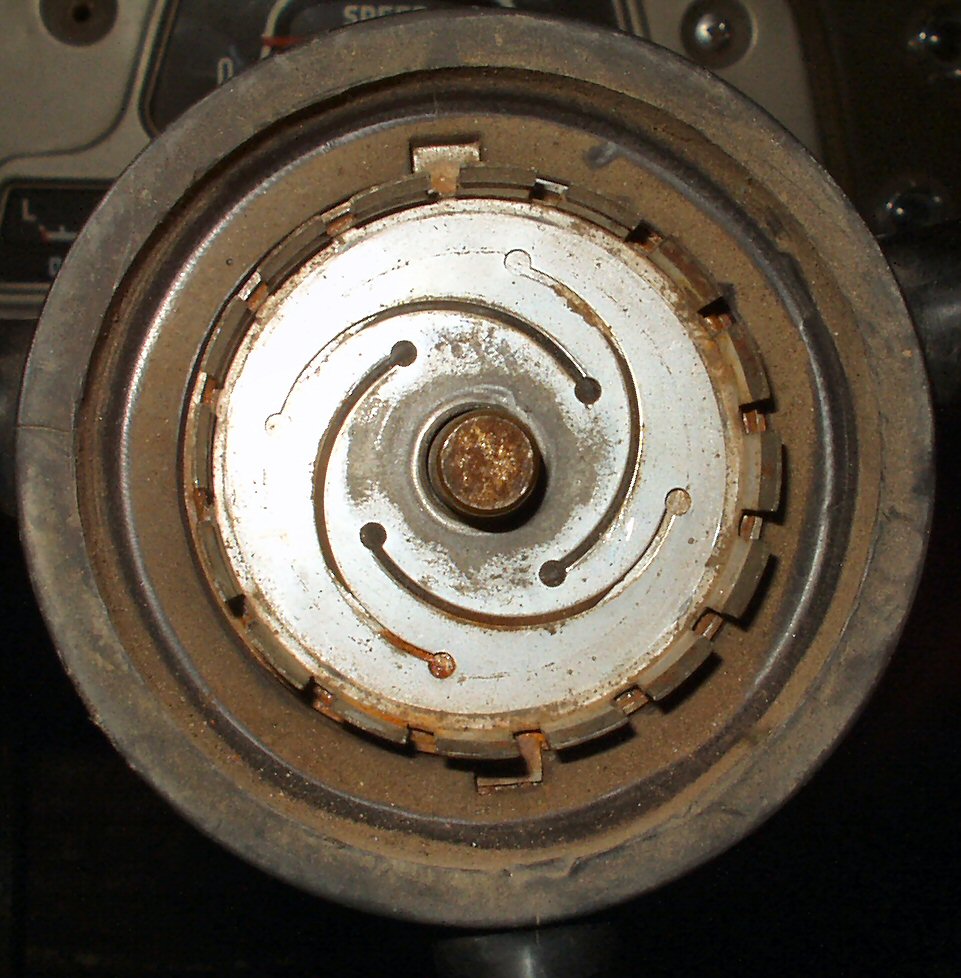
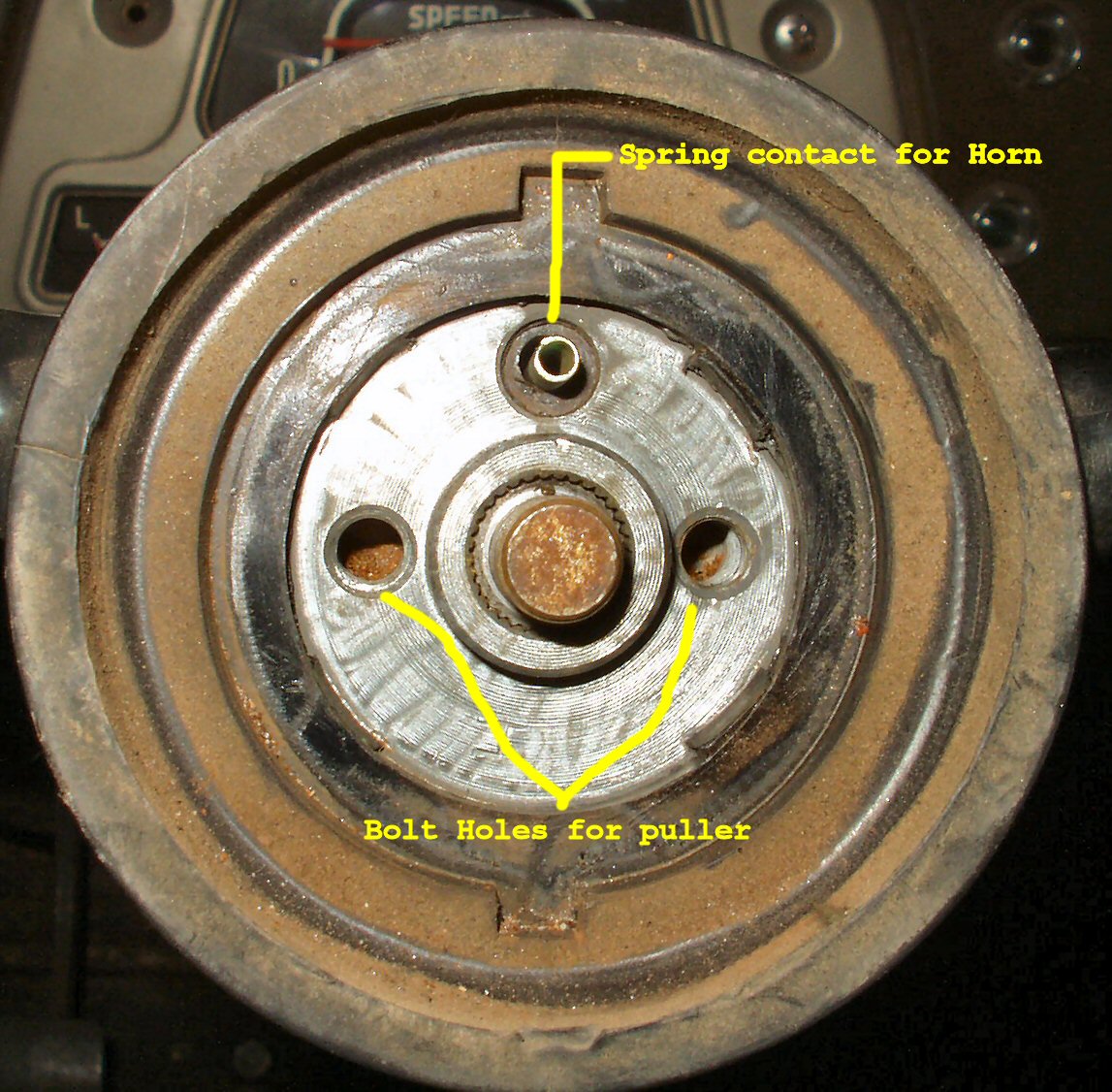
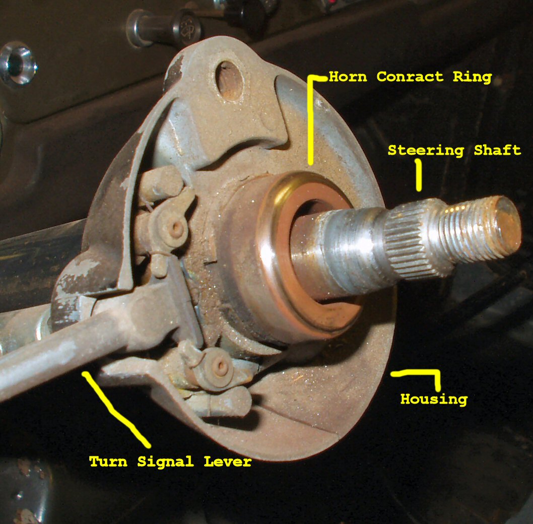
- Pop the horn button off the steering wheel and remove the 14mm nut holding the steering wheel on. Remove all the horn components See Fig. 1-4.
Fig. 1
Wheel Retaining Nut
Fig. 2
Cap Retaining Ring
Fig. 3
Horn Contact
Fig. 4
Horn parts
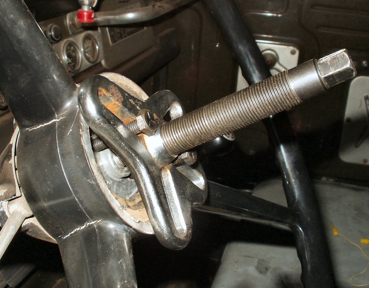
- Attach a steering wheel puller and pull the steering wheel. See Fig. 5-6.
Fig. 5
Pulling the Wheel
Fig. 6
Wheel Off
Fig. 6A
Housing Screw
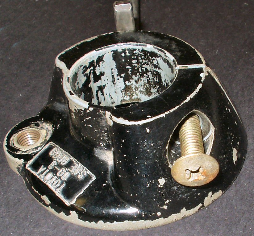
- REMOVE, don't just loosen, the large phillips screw on the passenger side of the turn signal housing. Now while twisting back and forth and pulling up, remove the turn signal lever housing. See Fig. 6A. A large rubber plug (Toyota calls it an insulator bushing) that has the horn contact and steering shaft bushing will come out of the end of the column. Refer to Page 8 Fig. 7.
- Remove the small phillips screw holding the turn signal housing clamp to the steering column and let it hang by it's wires. See Fig. 7.
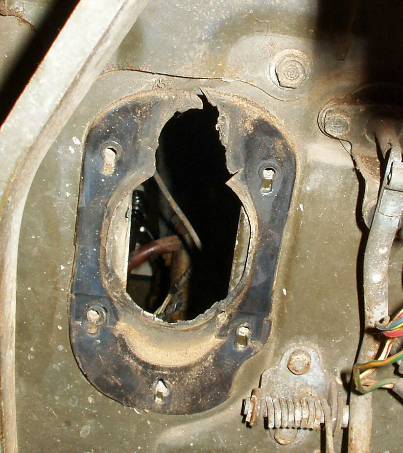
- Remove the 5 bolts holding the steering column dust boot or what's left of it to the firewall. See Fig. 8.
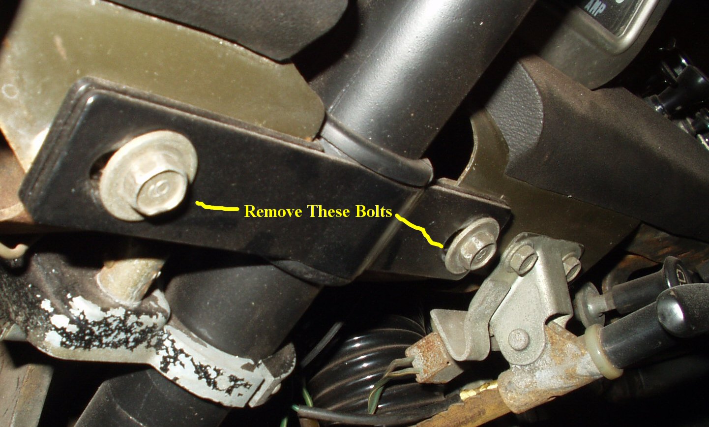
- Remove the two bolts holding the steering column clamp bracket to the dash. See Fig. 8A.
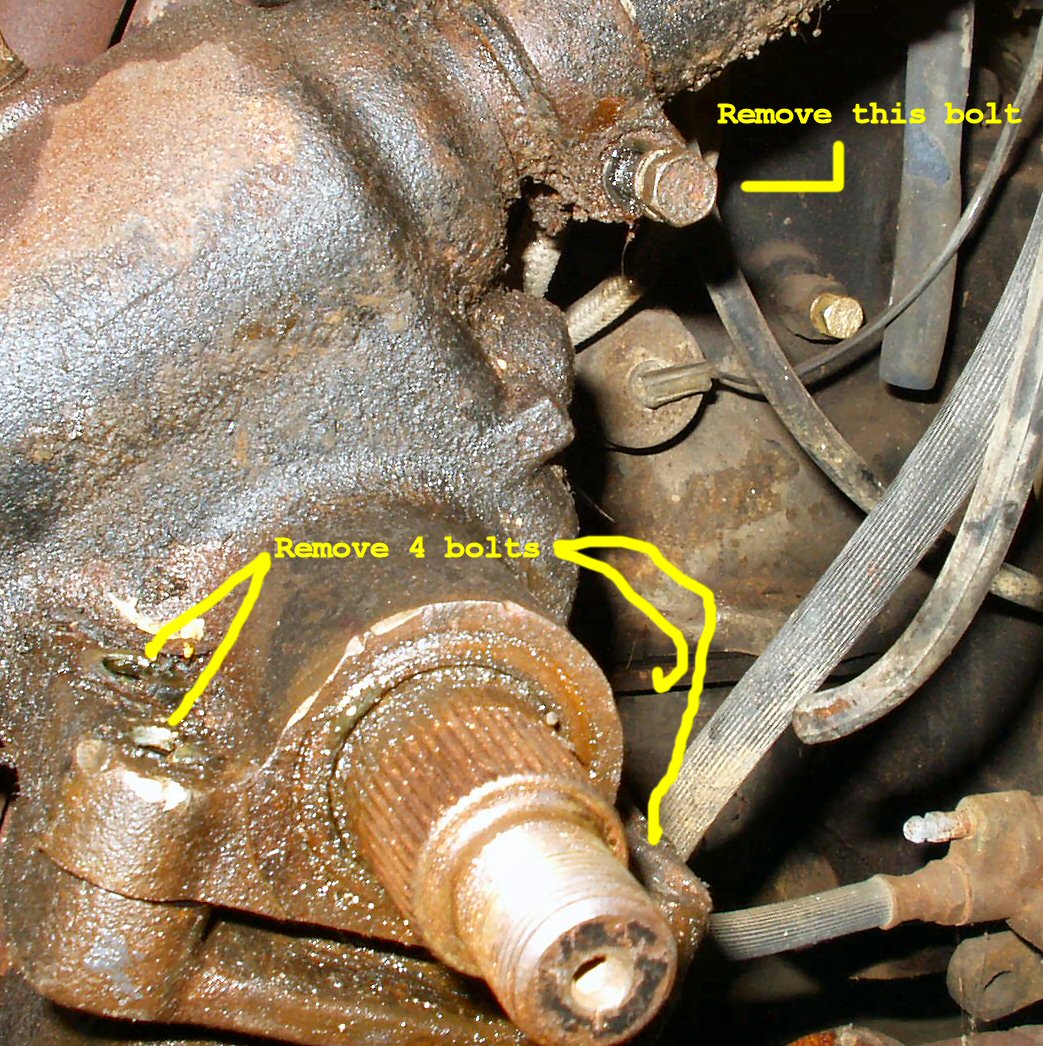
- Remove the clamp bolt holding the steering column to the steering box. See Fig. 10.
Fig. 7
Turn Signal Housing
Fig. 8
Column Boot
Fig. 8A
Steering Column Clamp Bolts
Fig. 9
Removing Box
Fig. 10
Separating Column from Box
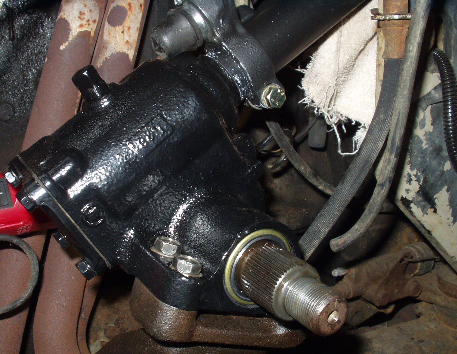
- Remove the 4 bolts holding the steering box to the frame mount. Be careful with the brake line and it's support bracket. See Fig. 9.
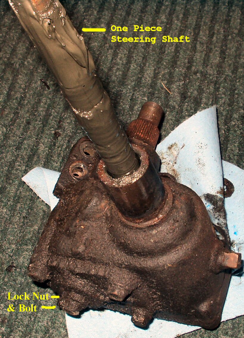
- Raise the box off the mount, then slide the whole box with column attached out the engine compartment. See Fig. 11.
- Remove the square plug in the top of the steering box and drain the oil (If there is any left after the seal failed.)
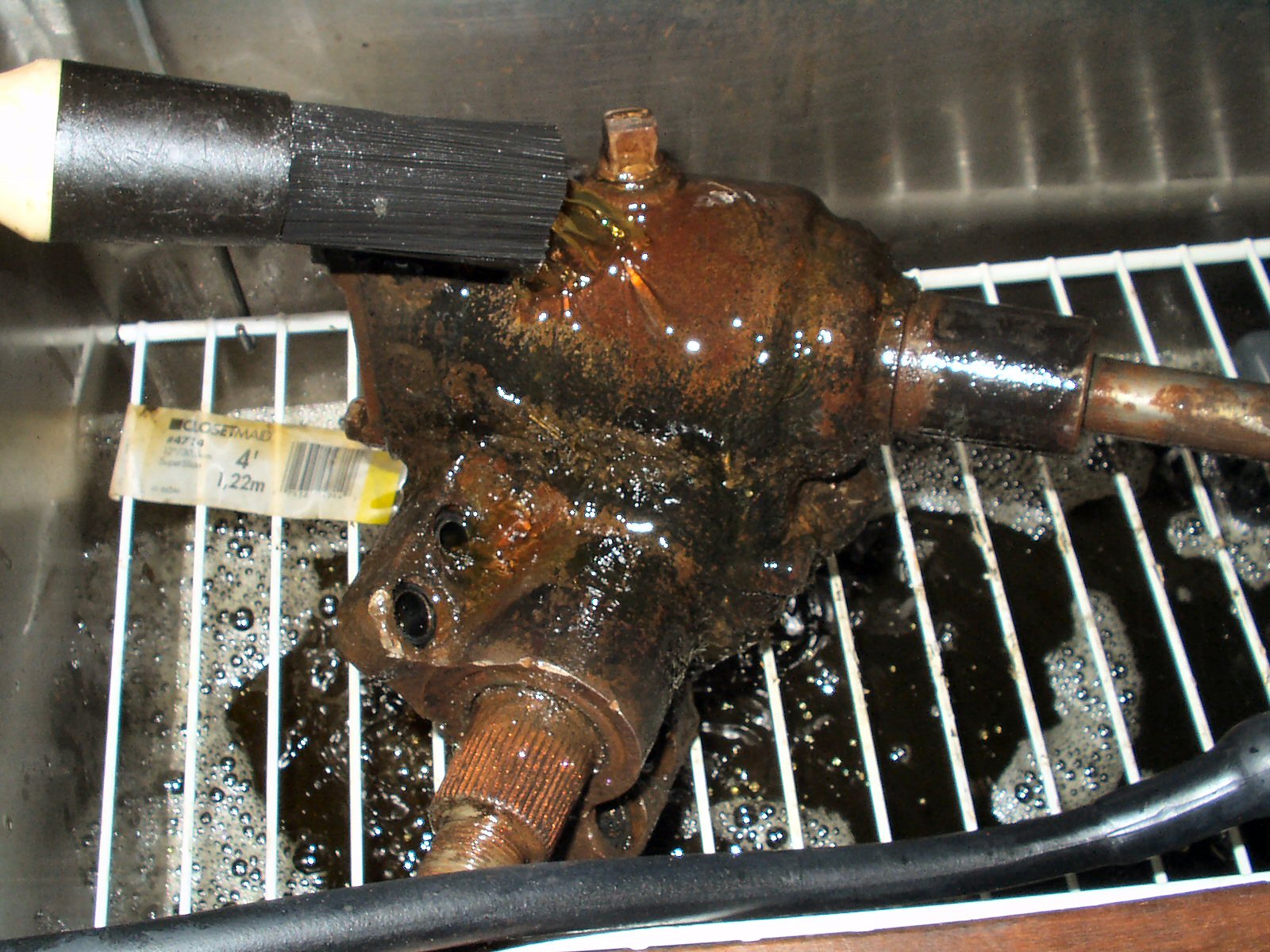
- Now would be a good time to clean off the crud on the box before disassembling it. I used my parts cleaning tank. See Fig. 12.
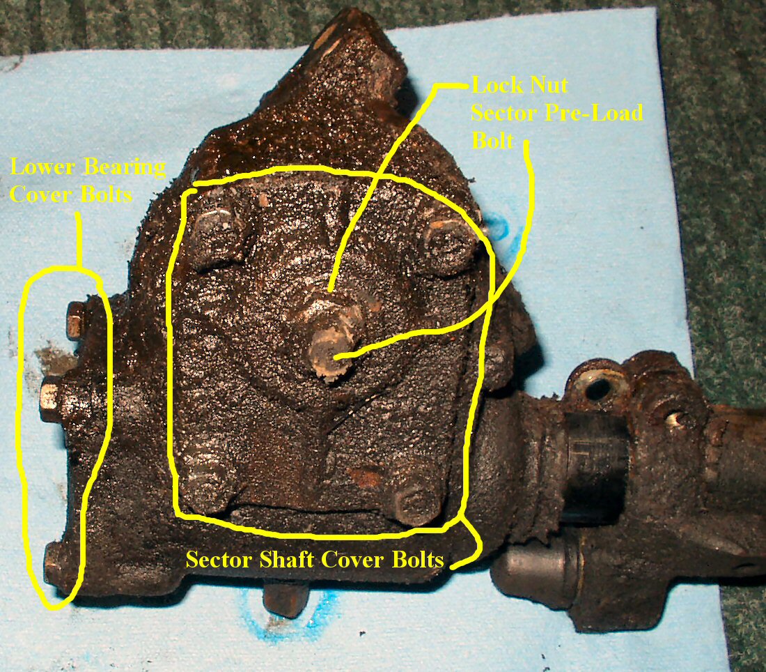
- Loosen the lock nut on the sector shaft cover and back off the square drive bolt to relieve the pre-load on the sector shaft. See Fig. 13.
Fig. 11
Column Removed
Fig. 12
Removing 34 years of Crud
Fig. 13
Sector Shaft Cover Bolts
Fig. 14
Bearing Cover Bolts
Fig. 15
Sector Shaft ready to be removed
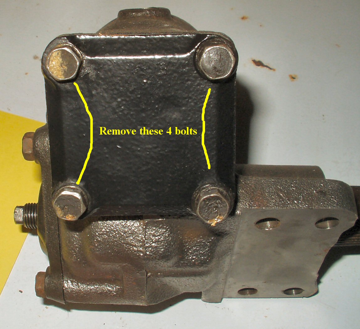
- Remove the 4 bolts holding the sector shaft cover on and pry the cover off. Unless you have new gaskets be careful and save this one!
- Remove the 4 bolts holding the worm gear lower bearing cover on. The thick 'gasket' under this cover is also the bearing pre-load shim! Do NOT discard it! See Fig. 14.
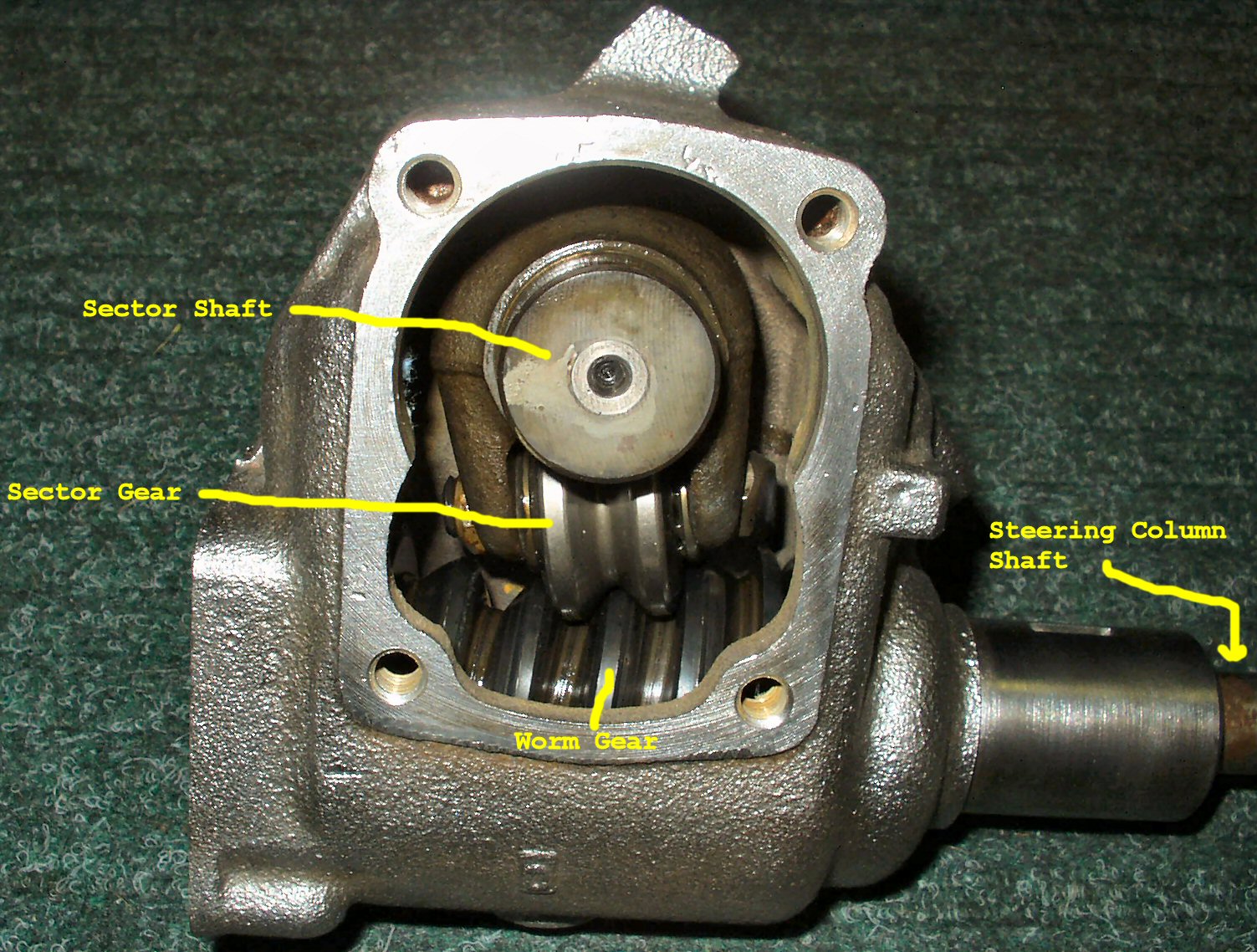
- Clamp the steering box in a vise letting the shaft stick out horizontally. Attach the steering wheel temporarily and rotate the steering wheel all the way to the left. Make note of a reference point on the wheel. Now rotate the wheel all the way to the right this time counting the total revolutions. (Mine was 5) Now rotate the wheel back to the left exactly 1/2 that number of revolutions (2 1/2). This will center the sector shaft on the worm gear and allows it to be removed easily. See Fig. 15.
- Remove the steering wheel and sit the housing upright on a bench. With a rubber mallet tap the sector shaft end (where pitman was attached) to drive the sector shaft out of the housing. Make SURE to get all the shims that were on the end of the shaft! There should be a thick spacer plate and several much thinner shims. Mine had 5 .040 shims. Your box may have more or less and they may be different sizes. The thick spacer plate has a side with a tapered face, the tapered face goes toward the sector gear and the shims go next to the plate. Set these aside for now, you will use them to adjust the play in your box later.
- Use the rubber mallet to tap the end of the steering column where the steering wheel attaches to drive the worm gear and lower bearing race out of the housing. Slide the long column all the way out. If it won't come out with the rubber mallet then place a piece of wood over the end of the column and get out the metal BFH. Just don't mangle the threads on the end! See Fig. 16-17.
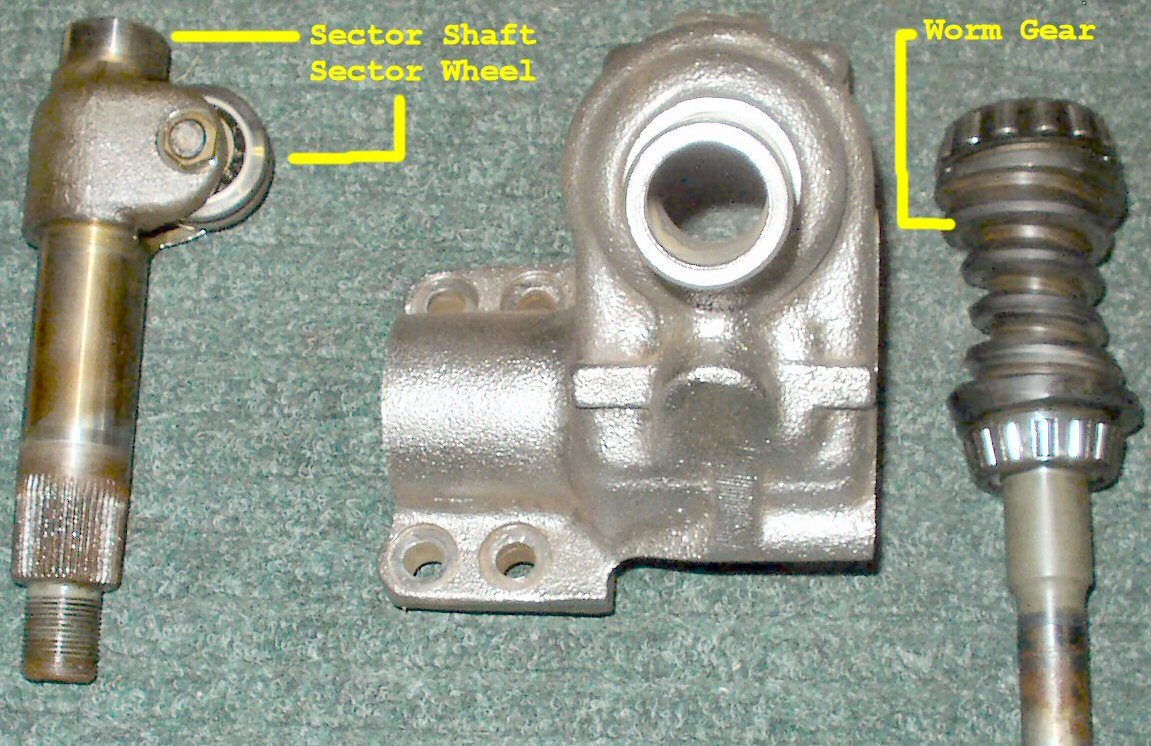
Fig. 16
Sector Shaft & Sector Wheel
Fig. 17
Steering Shaft
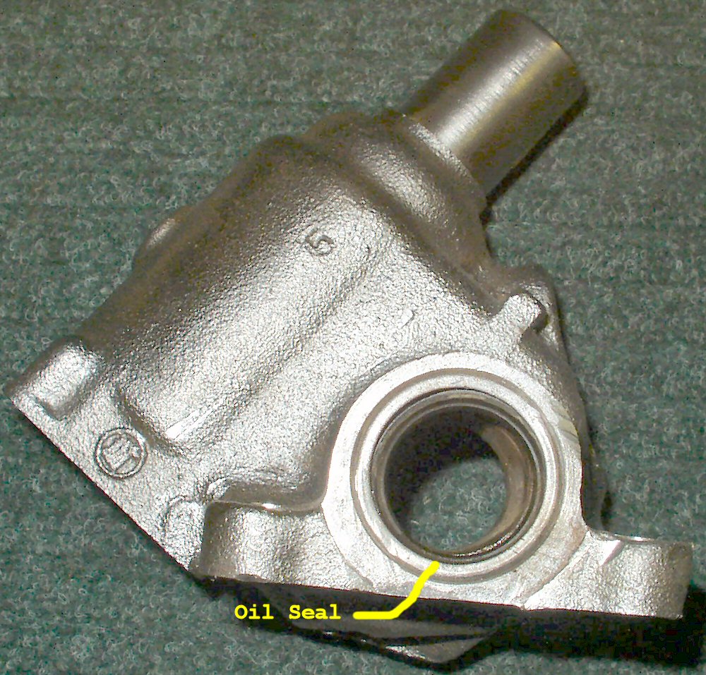
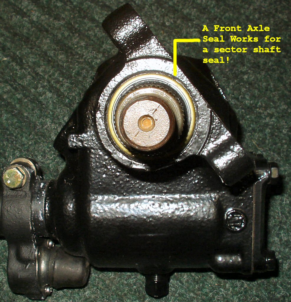
Fig. 18
Sector Shaft Oil Seal
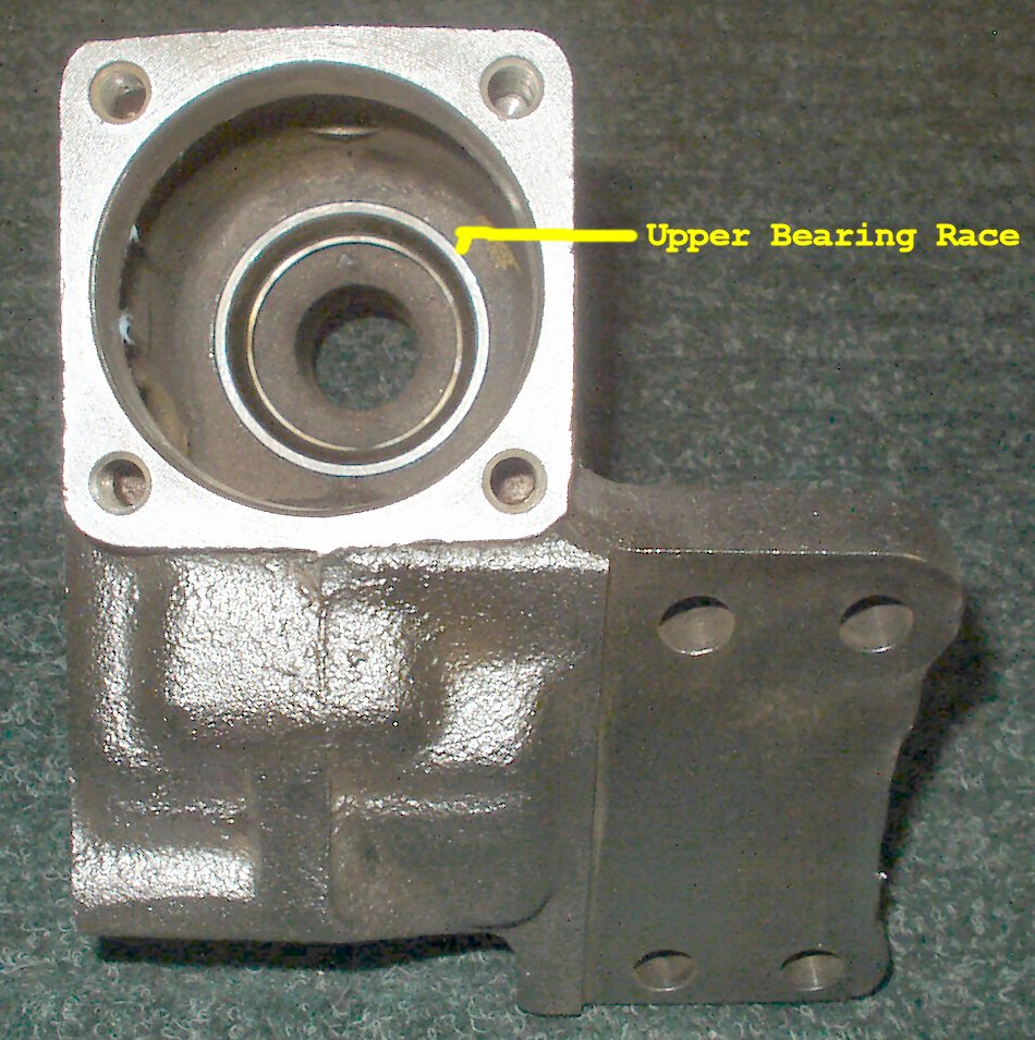
Fig. 19
Upper Bearing Race
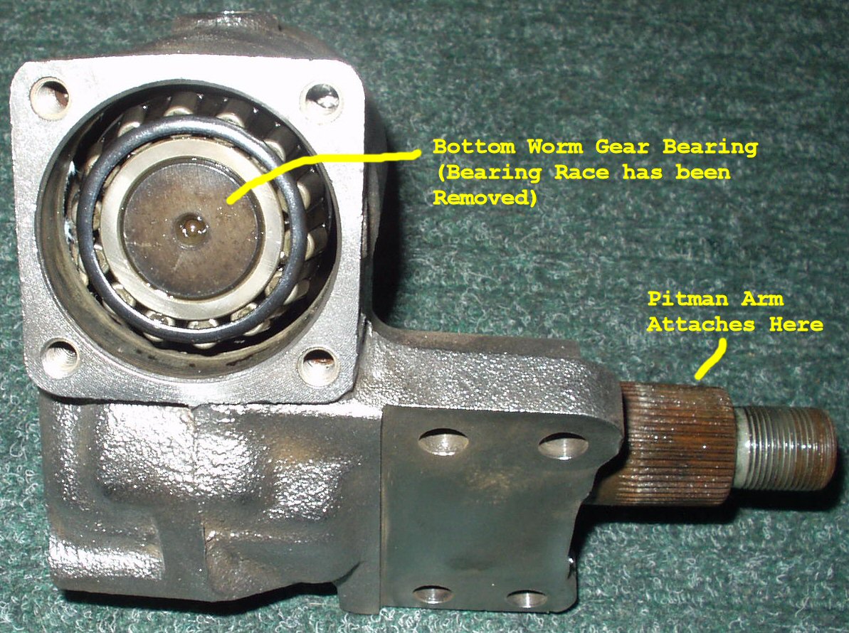
Fig. 20
Bottom Worm Gear Bearing
Fig. 21
Sector Shaft Bushing Location
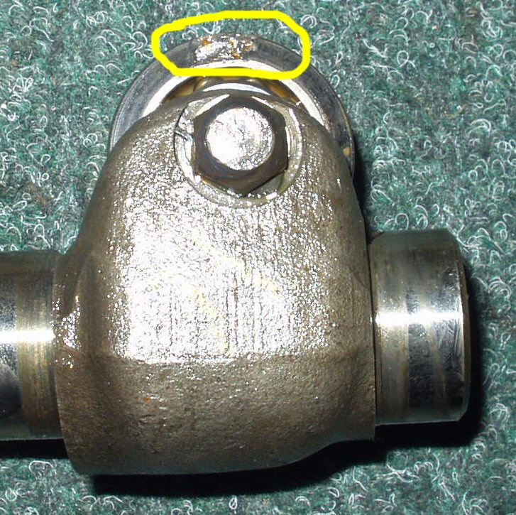
Fig. 22
Sector Defect
- Use a seal puller and remove the sector shaft seal. See Fig. 18.
- De-grease the housing and if you have one set up, put it in a de-rust tank to get all the rust off. Prime the housing then paint with a good epoxy or enamel paint or powder coat it.
- While the paint dries inspect the bearings, races, worm gear, sector wheel and sector shaft bushing for scoring and wear. See Fig. 19-21. My sector wheel had a casting defect that was causing a 'jump' when the steering wheel was cranked all the way to the right. See Fig. 22. I replaced it with the sector shaft from the 1969 box I have.
- Marks Off Road no longer sells the parts needed to rebuild these boxes. However Marks Offroad can rebuild your box to like new condition if you prefer! For reference: The sector shaft seal is 32 x 44 x 9 and the Toyota PN is 90310-32024.
Reassembly and Adjusting
- Ok so you have cleaned everything up, have all your parts in hand and are ready to start reassembling.
- DO NOT install the sector shaft seal yet! That is one of the last things you will do. We first need to adjust the sector wheel to worm play.
- Insert the long steering shaft with worm attached into the housing. Coat the lower bearing race with a coat of 90W and tap it back into the housing.
- Put the lower bearing cap back on with the thick gasket/shim. Tighten to 16 ft lbs. This sets the pre load on the worm bearings.
- Insert the sector shaft into the housing with ALL the shims in place that you removed with the sector wheel 90 degrees to the worm as shown in Fig. 15. Don't forget the proper orientation of the spacer and shims!
- Install the cover and gasket over the sector shaft, tighten the bolts down to 16 ft lbs.
- Clamp the steering box firmly in a large vise. Re-attach the steering wheel and loosely put the pitman arm back on.
- Now tighten the screw in the end of the sector shaft cover until there is just a bit of friction needed to turn the steering wheel. You DON'T want it hard to turn, just enough to provide some 'feedback'. This sets the sector shaft end play. (Note: This is the screw everyone thinks will tighten up their steering. It does NOT, it just makes it wear out sooner! Play is removed by adding or removing shims.)
- Rotate the steering wheel all the way to the left. Now all the way to the right this time counting the revolutions. (Mine was 5) Now back to the left exactly 1/2 that number of revolutions (2 1/2). This again centers the sector shaft on the worm gear.
- With the sector wheel now centered hold the pitman arm so it can't move and rotate the steering wheel back and forth to see how much play is in the worm to sector steering. Mine was over 1/4 revolution! It's supposed to be 1" movement of the steering wheel.
- If your play is over 1" then loosen the sector shaft pre-load screw, remove the sector shaft cover and remove the sector shaft. Remove one of the shims from the shaft and re-install it. Repeat steps 8-10 until the play in the steering is about 1". (Note:You now have to turn the end play screw in further because of the removed shims.) I had to remove all 5 of my .040 shims leaving nothing but the spacer plate to get it to about 1.5 of play.
Fig. 22
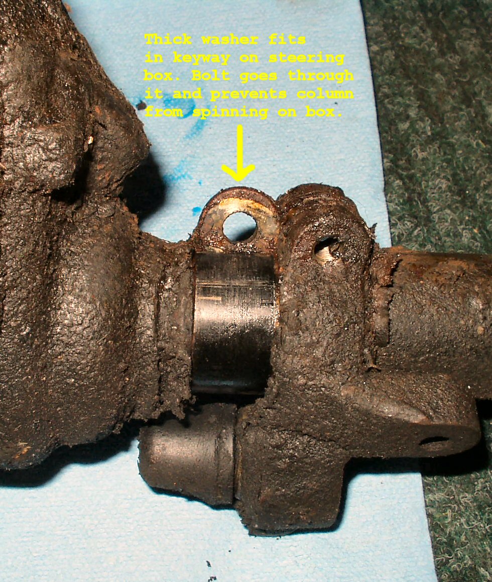
Fig. 23
Fig. 24
Fig. 25
- Once you have the play out of your steering remove the sector shaft one last time and NOW install the sector shaft seal. (Note: an inner axle seal for my Cruiser was an EXACT fit for the sector shaft seal!) Make sure to pack the lip of the seal with grease. See Fig. 22.
- Coat the sector shaft and the sector bushing in the housing with a good coat of 90W. Carefully put the shaft back in so as not to damage the seal. Put the cover back on and readjust the sector shaft end play.
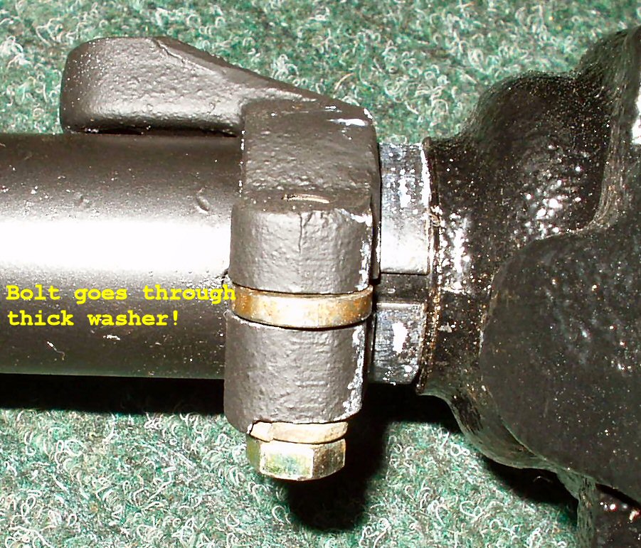
- Reassemble the column to the steering box. Don't forget to put the thick washer between the ears of the column clamp! This washer fits in the key way on the steering box and prevents the two from rotating relative to each other! See Fig. 23.
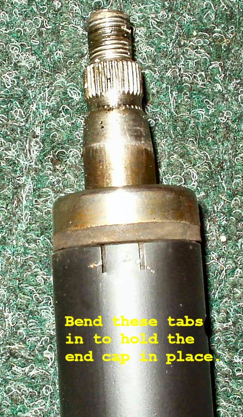
- When you put the rubber insulator end cap back in don't forget to bend the pinch tabs at the top of the column back in just enough to keep the rubber insulator from spinning. See Fig. 24.
- Carefully guide the column back through the hole in the firewall and put the steering box mounting bolts on finger tight. Don't forget the brake line bracket that goes under one of the bolts!
- Slide the firewall rubber boot over the column. Now put the rubber gizmo for the dash clamp around the column and put the clamp on. Don't forget to position the turn signal housing so the rod goes through the dash correctly!
- Tighten the steering box bolts to 75 -90 ft lbs, THEN the dash clamp bolts, THEN the rubber boot bolts.
- Put the turn signal lever housing back on guiding the rod going down to the signal switch into the slot. You MUST align the place where the phillips screw goes with an indention in the column EXACTLY or you will mess up the phillips screw when you tighten it down.
- Install the pitman arm using the marks you made earlier. Install the lock washer and nut. Torque the nut to 120-140 ft lbs.
- Enjoy your new tight steering!