![]()
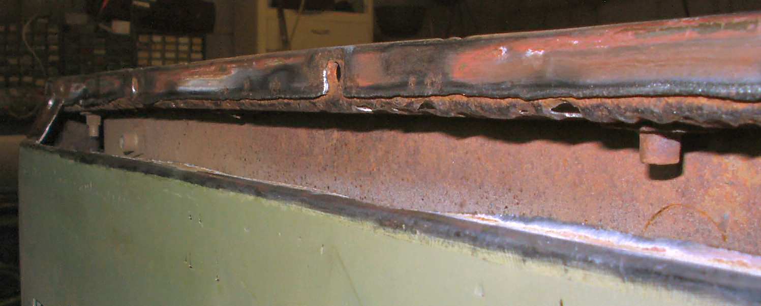
Fig. 1
Passenger Side
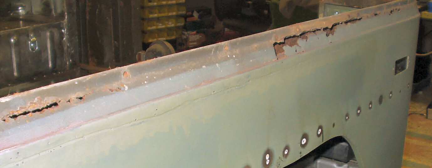
Fig. 2
Drivers Side
Fig. 1 Passenger Side |
Fig. 2 Drivers Side |
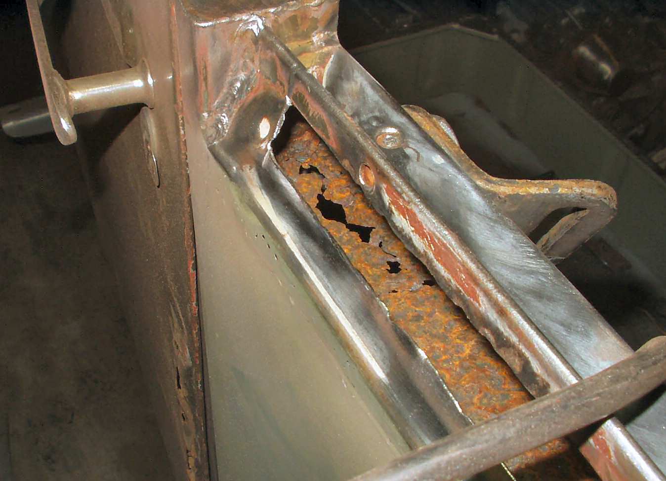
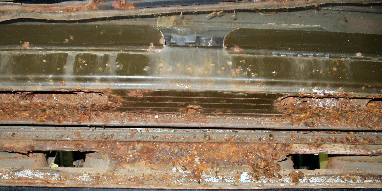
When I pulled the top off for the first time after getting the wheel wells finished I was faced with a lot of rust on the tub rail. See Fig. 1-2. I still have not figured out how the sides of the rails can be rusted clear through but the bottom of the channel is not? Water stands on the bottom and run off the sides, but the side rust through... Oh well...
Fig. 3 Pretty bad... |
Fig. 4 Patch cut ready to weld |
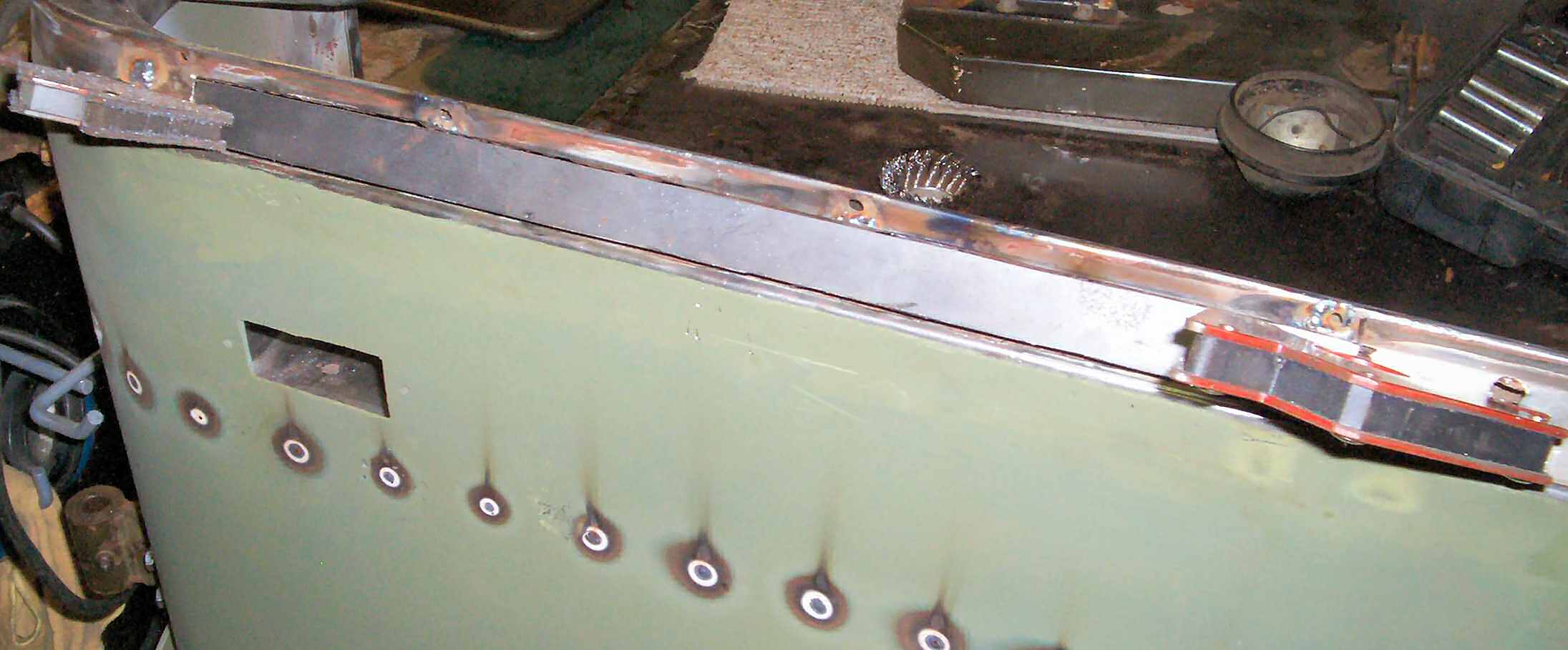
Fig. 5 Welded up ready to grind |
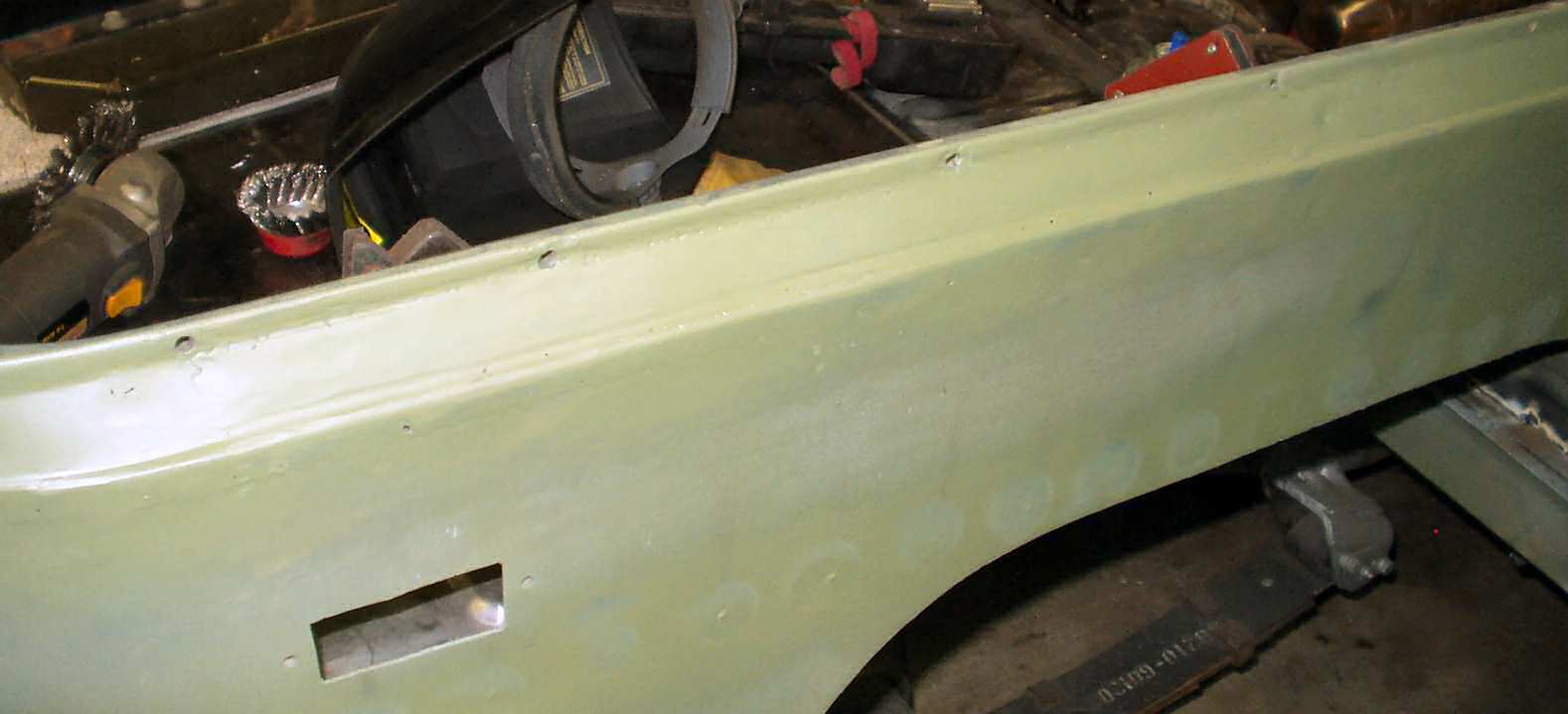
Fig. 6 Finished ready for body work |
I started on the passenger side for practice as it was the least rusted. I used a 1/8" cut off wheel on a 4 1/2" grinder to cut back to good metal. See Fig. 3.
Using a wire wheel I removed as much rust as I could and shot the cavity full of a galvanizing primer. While that was drying I cut a piece of 16ga sheet to fit the hole. Using a couple od welding magnets I placed the patch and started tacking it in place. See Fig. 4. This took a while! that patch is 18.5" long x 1" tall so I had 39" of welding to do one small spot at a time. The top edge was still a bit rusty and thin and even with .023 wire and the lowest setting I kept burning through. Anyway Fig. 5 shows the completed weld.
An hour with the grinder and a fine flap wheel then a quick shot of primer and I was done with that side. See Fig. 6.
Fig. 7 Opened up |
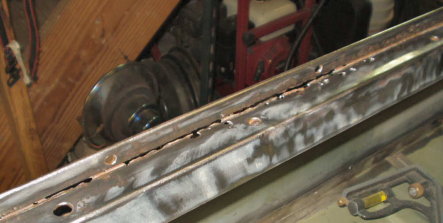
Fig. 8 Inside Rail |
Fig. 9 Worst one... |
The drivers side rust was much more extensive and will have to be done in three separate sections. Fig. 7 shows the entire outside will have to b replaced. Fig. 8 shows the inside is perforated through. Worst of all is Fig. 9 which shows the BOTTOM of the rail is gone near the door post. At this point I decided to just replace the entire tub rail on this side. A member of our local Land Cruiser club had an old tub that had this piece.
Fig. 10 Inside Tub |
Fig. 11 Front |
Fig. 12 Passenger Side |
Fig. 13 Drivers Side |
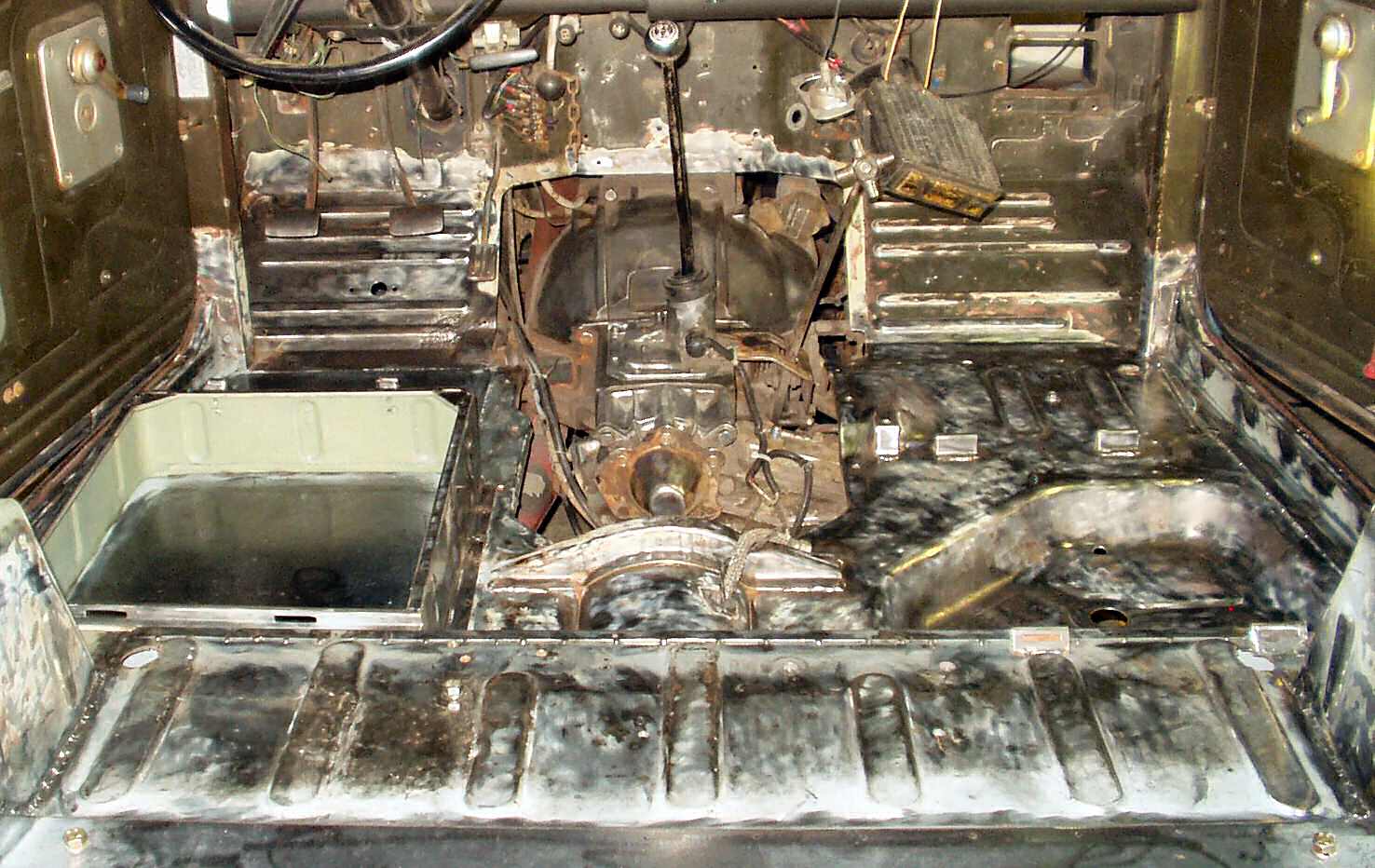
I ordered the sand colored Durabak figuring it would hide dirt better than black and not be as hot. Also I plan on painting the Cruiser Desert Sand... But there is a bit of work to do to prep for the application of the Durabak so...
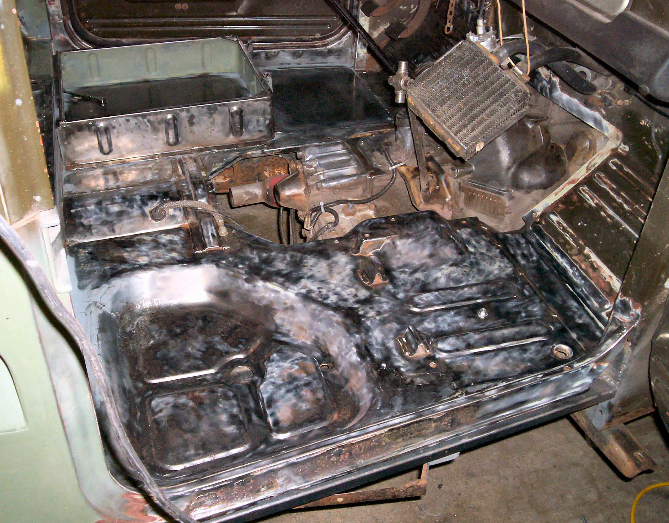
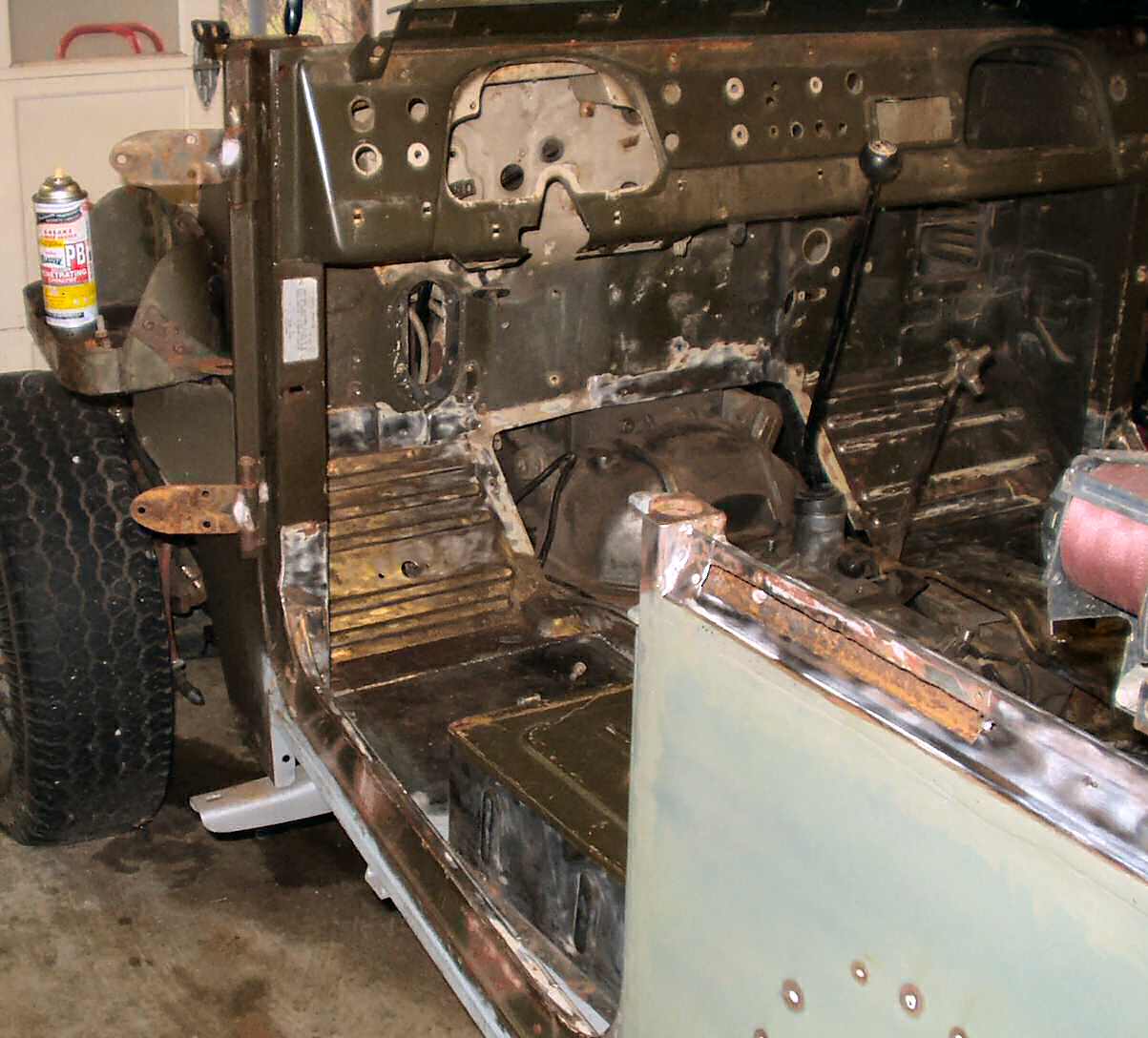
After getting the tub fixed I took a knotted wire wheel and started removing the rest of the paint and rust from the front section and the rockers. This took the better part of a day and made a terrible mess of my shop! See Fig. 10-13.
It was at this point that I realized I would be doing a half assed job if I just did the floor without doing something about the mess under the dash. I had never planned to pull the body off the tub till a few years down the road when I would have a better shop and more space. This just wasn't sitting well with me so.... I stopped prepping and started tearing into the dash removing everything! I guess this just turned into a frame off!
Fig. 14 Stripping the Dash |
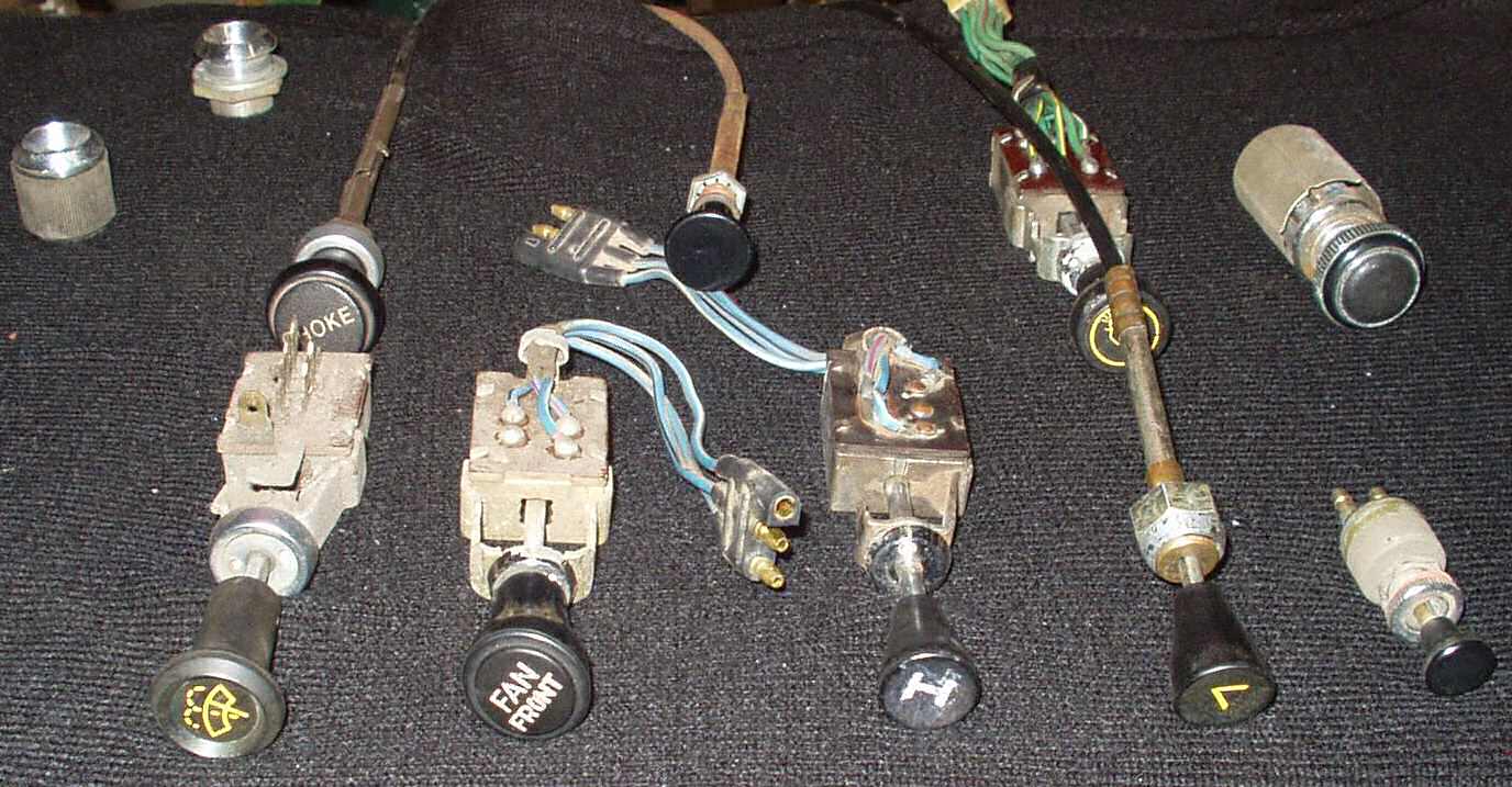
Fig. 15 Dash Controls |
Fig. 16 Rusted badly |
Fig. 17 Last one's a bitch! |
Fig. 18 That might hurt! |
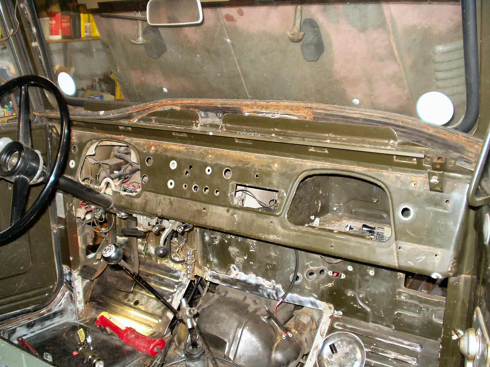
I was in such a rush to get this stuff off I did not take a lot of pics. I started by removing the heater core and all heater hoses and splitters from under the dash then also removed all hoses from under the hood. The upper dash pad was next. This is held on with 5 small phillips screws. Once the screws are removed give it a good yank and it will pop off. Next I removed the lower dash pads. Then all the dash controls as seen in Fig. 14-15. At this point I got the camera and documented the entire underside of the dash so I would know how to put it all back together. Under Dash Slide Show.
The steering column/steering box was removed next followed by the pedal assembly after removing the brake booster/master cylinder and clutch master. The wiring harness came out next. Surprisingly easy I might add! Then the 4x4 vacuum shifter, emergency brake, gas pedal and the cowl vent linkage were removed. Again I documented the under side of the dash with all the stuff removed. See the slide show above.
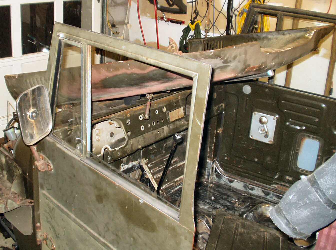
When I had folded down the windshield earlier I was surprised at the amount of rust around the frame in the defroster areas on both sides. Turned out the windshield had been leaking at the place where the two ends of the glass seal come together for years! I now know there was supposed to be a 'lock' in there...That explained all the rust under the dash also. See Fig. 16.
To remove the windshield I used a Mapp gas torch to heat each phillips screw then used my SST (Air hammer with a phillips bit attached) to loosen them. They all came out but one. For the last one I welded another bolt to the head of the screw and it came right out. See Fig. 17. When I removed the windshield I discovered that the hood will fold all the way back! See Fig. 18. If you ever remove the windshield and take a spin make damn sure to latch the hood!

Fig. 19 Hood Removed |
Fig. 20 Doors off
|
The hood came off easily as I was able to get some PB Blaster on the bolts a few days before I removed them. See Fig. 19. I set it aside for further removal of parts and proceeded to remove the doors. Amazingly the doors bolts ALL came out without breaking! Even the hinge to body bolts came out easily. They also had been pre-soaked with the PB-Blaster. See Fig. 20.
All that was left to lift the body off the frame were a few things on the fire wall and the remaining body mount bolts. I had to use a hack saw to cut off four of the body mounts. Finally the body was free of the frame!
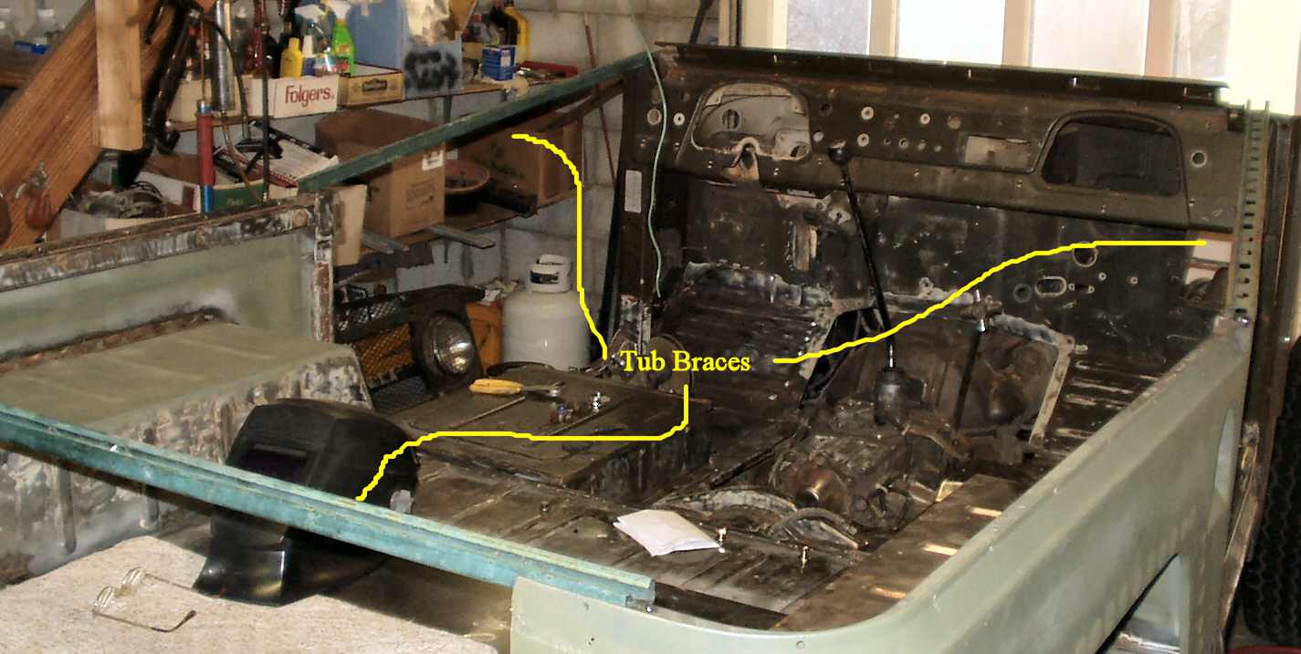
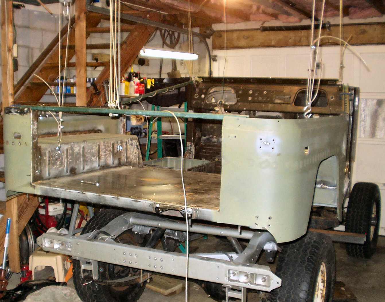
Fig. 21 Bracing the tub |
Fig. 22 Cowl Brace |
At this point I decided I'd better weld in some support braces so the tub would retain it's shape while moving it around. Using Uni-Strut pieces picked up at a job site I installed one across the tailgate area to keep the quarters from spreading and two from the cowl to the door posts. See Fig. 21-22.
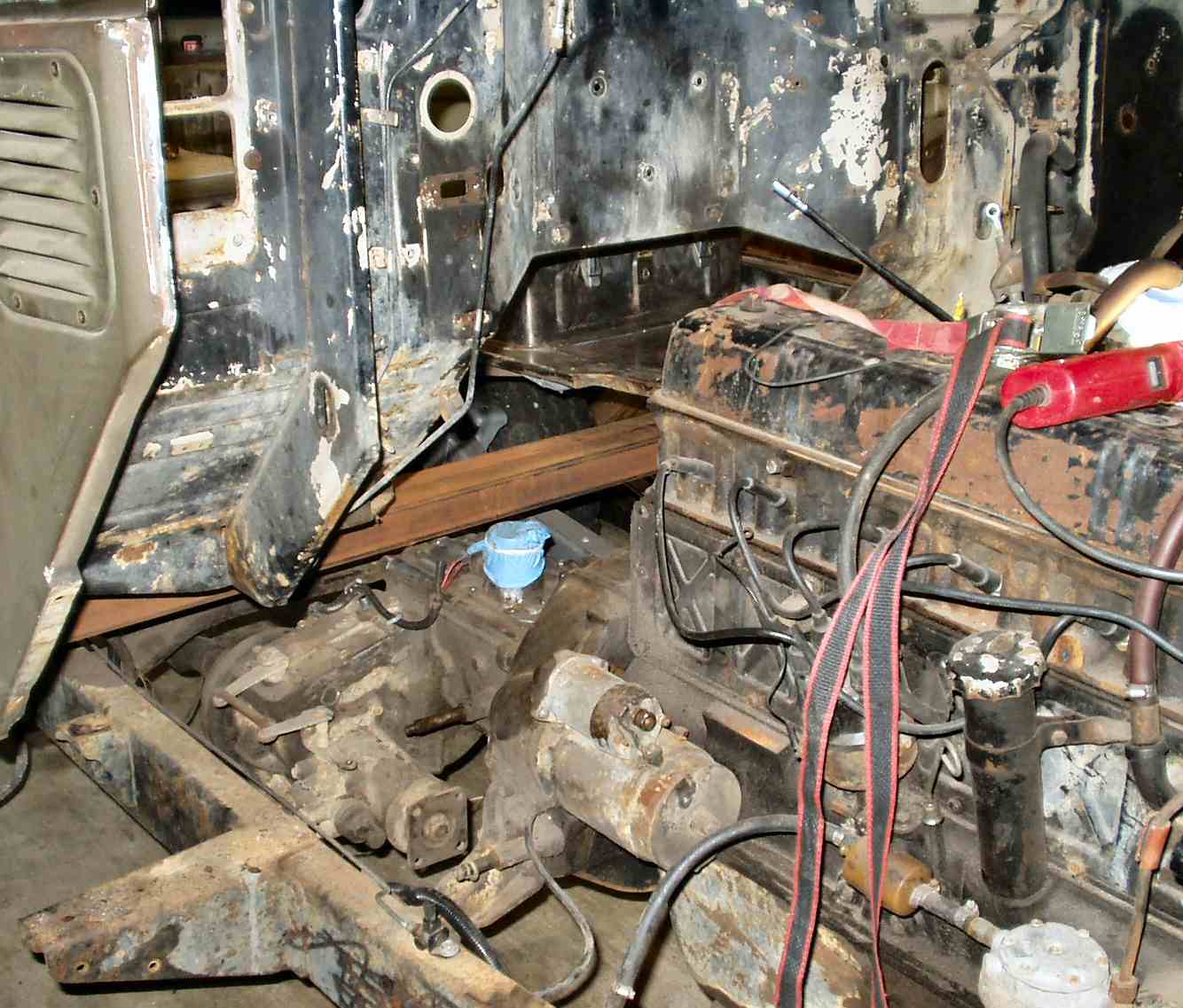
Ok so I have no overhead lift, there is not enough vertical room to use my hand winch, my brother is disabled and I have a bad back! So how did we do it? Why with a Hi-Lift of course!
Fig. 23 Another use for a Hi-Lift! |
Fig. 24 Precariously balanced? |
Fig. 25 Getting there |
Fig. 26 Lift Kit? |
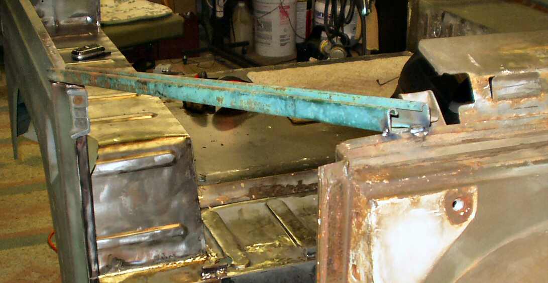
We used two metal saw horses, a 10' piece of 2 x 4 rectangular tube, some wood blocks and of course the Hi-Lift. Fig. 23 shows where we jacked from. This allowed us to get the tubing across the frame then it was just a matter of moving the jack from side to side. I would jack and my brother would slide in a new crib. Fig. 24 shows the body apparently sitting precariously balanced on the saw horses. In reality it was very solid due to the tubing running all the way across under the body. You can see the tube in Fig. 25. Still, I only left it like that for one day!
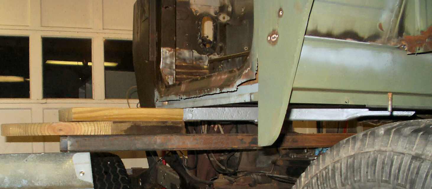
If you ever wanted to know just how high the bed of the truck needs to be to clear the frame completely then look at Fig. 26! Turns out it's three feet!
The next day after my brother left I had to figure out how to get the tub on a secure 'footing' yet still be able to move around it easily. My only option was to hang it from the ceiling!
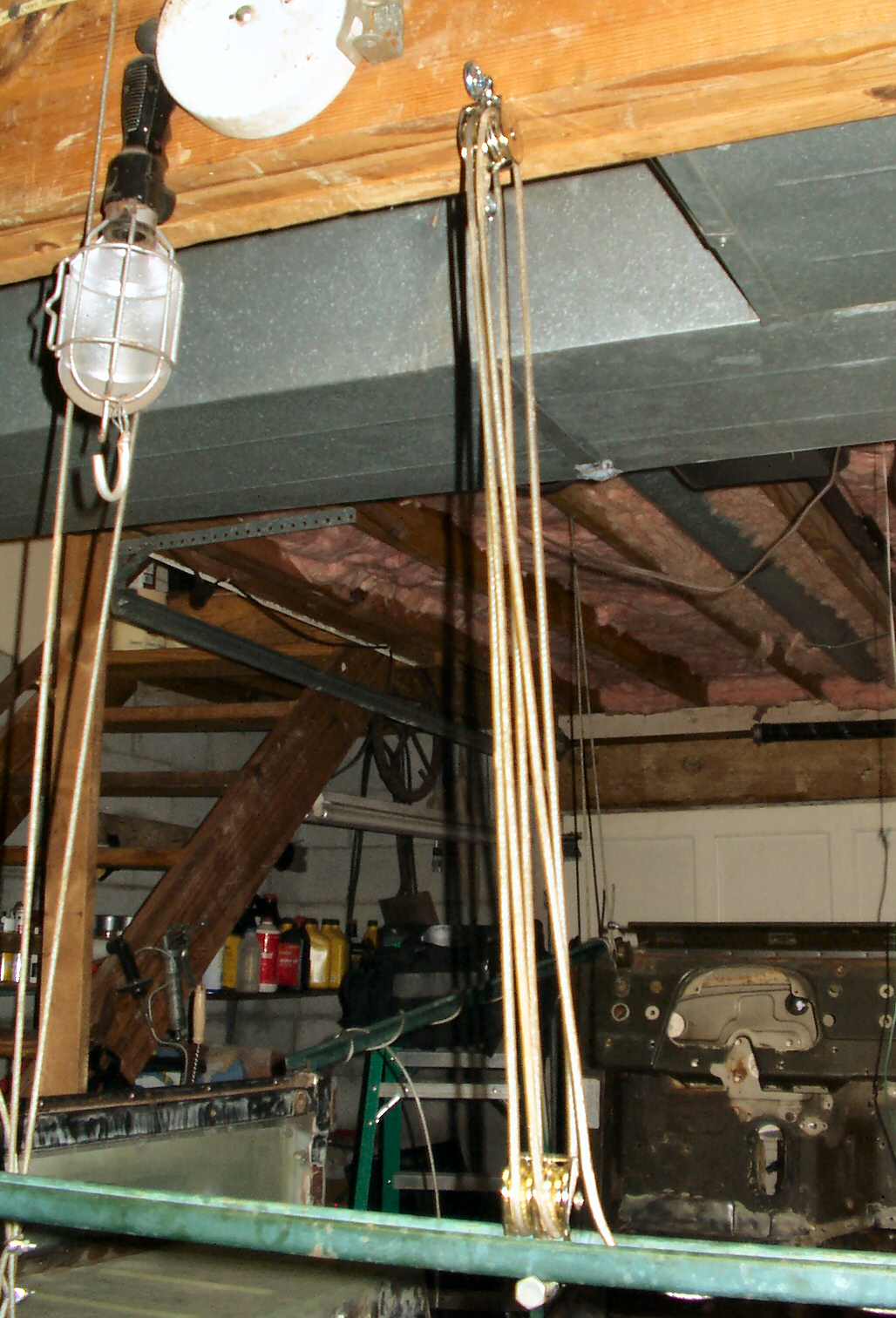
Fig. 27 Block & Tackle? |
Fig. 28 Rear View |
Fig. 29 Just Hanging Around |
I had a couple of small metal double pulleys left over from a flower pot hanging project (don't ask...) I used these with some vinyl covered wire rope to create a small block and tackle. I used a lag screw to anchor it into the main beam of the house and a bolt to anchor it into the welded on support. I was able to easily lift the rear of the truck myself! Se Fig. 27.
Once I had the rear lifted I tied off the wire rope then made up four sections of wire rope to hang each corner. I screwed four more lag screws into floor joists above each corner of the truck then mounted the two rear ropes to some anchors I installed on the truck. I let the block and tackle down so the tub was now hanging on the two rear ropes. See Fig. 28.
I moved the tackle to the front and repeated this process. Up front I hung it from the welded on supports. I had to go back and forth twice to get it to a height that would allow the frame to roll out from under it without catching on anything. See Fig. 29. Overall it took about 1.5 hours to do this by myself.
Next up : Pulling the Engine/Tranny/T-Case
.
Hosted by Global Software, Inc.
©1998 - 2023 Mark C. Baker Web Designer
Please: No part of this web site may be used without express permission... email mbaker@globalsoftware-inc.com for permission.