Pulling Engine/Separating Tranny from
T-case and Engine
Fig. 1
Winch Mount
Fig. 2
Slightly Bent!
Fig. 3
Bumper Removed
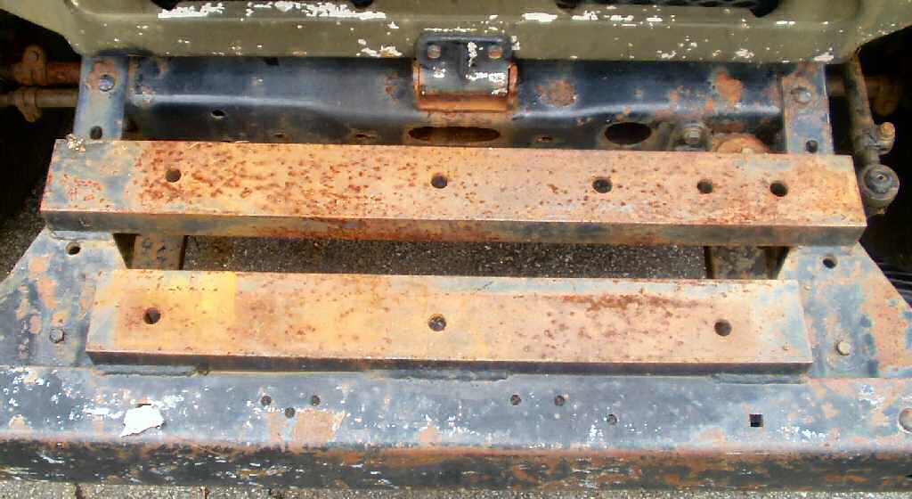
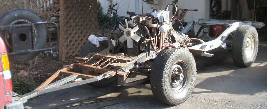
Before I pulled the engine/trans/t-case I needed
to remove some extra parts put on by the original owner. Fig.
1 shows the winch mount he had. As you can see he welded on some nice
thick C-channel to the frame triangular pieces and the front bumper. I will
run a winch eventually and will either put this channel back on or make a new
version.
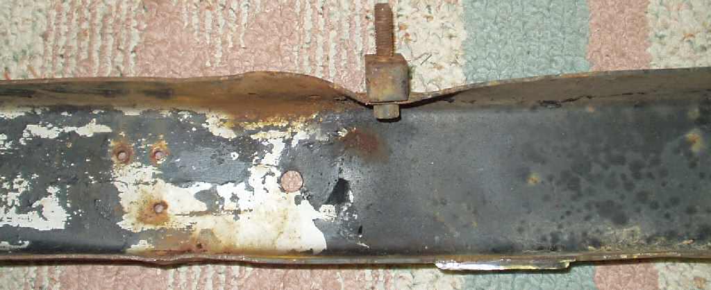
I cut the welds on the front channel and bumper
with a cut off wheel then broke all the bolts to remove the bumper. Once the
bumper was off I found out what trying to pull a fork lift that had run off
a ramp onto soft ground back on the ramp will do to a bumper! My brother had
done this with a large chain he hooked on the bottom lip of the bumper. See
Fig. 2. I will try to straighten it with the shop
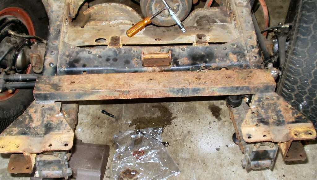
press but I think I will just end up making one for it. Fig.
3 shows the rusty frame in the front.
Fig. 4
Booty Tow Bar!
Fig. 5
It works!
Almost ready to sandblast frame
Fig. 6
It floats!
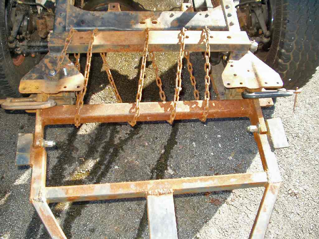
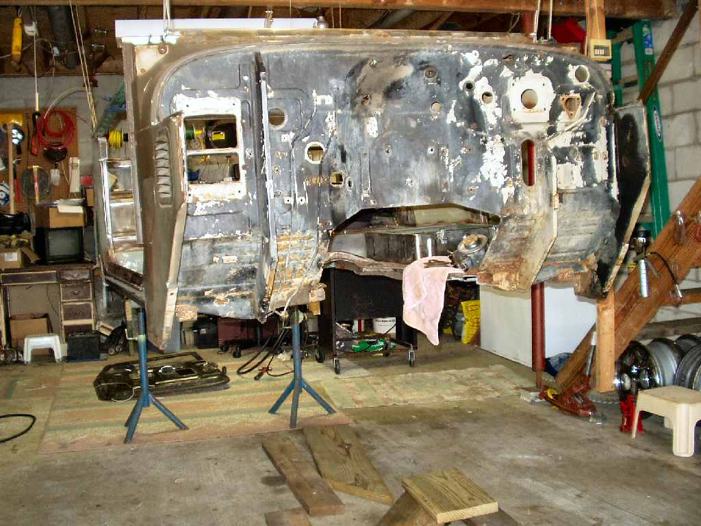
Now that the body is off the frame I needed a way
to safely move the chassis in and out of the garage. My drive slopes down so
I could not just push it in and out. I had a tow bar I used on my Pathfinder
so like any good hillbilly I pressed it into service. See Fig.4
for the ultimate booty attachment! :-) Later I will re-do this bar for towing
the FJ. Fig.5 shows it in use.
I knew the body of the FJ was pretty
light but had no idea it would float! See Fig. 6.
Air Cruiser?
Since I had such good access to
the engine I decided to fab up the power steering system before pulling it.
I made a full write up for that. See it here Power Steering
Fab work.
Fig. 7
New Hoist!
Fig. 8
New Engine Stand!
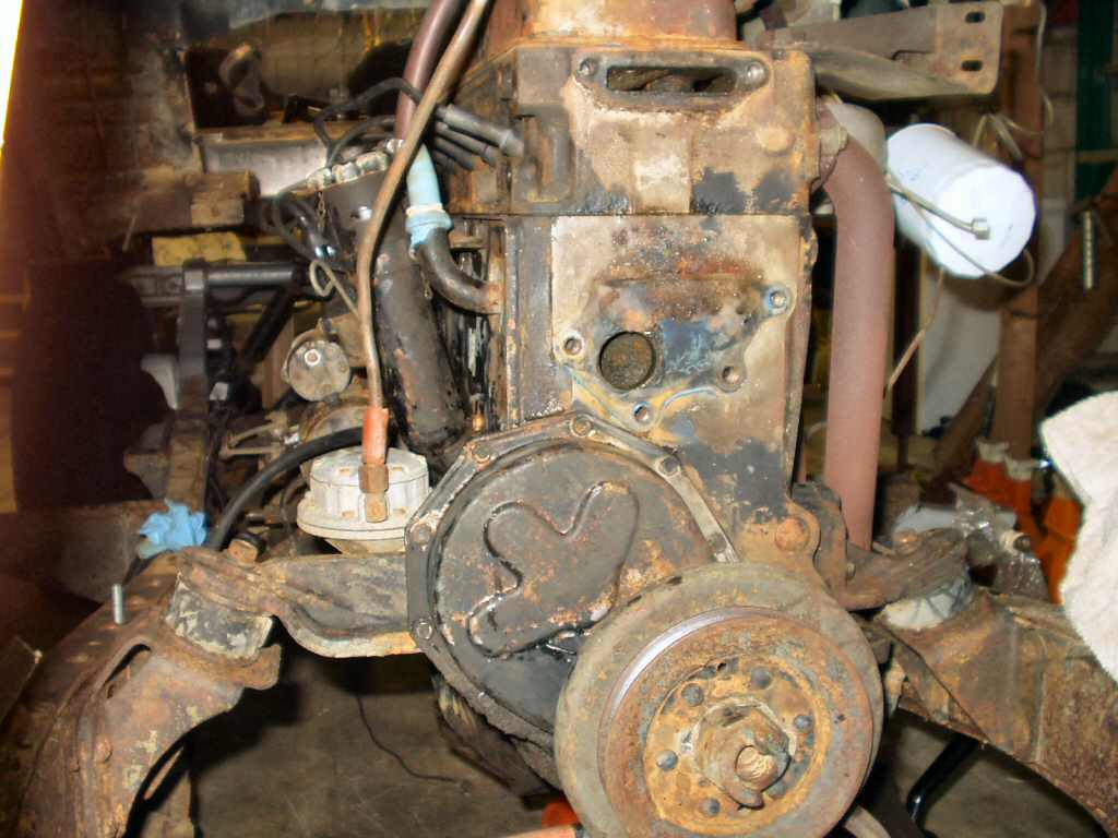
Once that was done I started stripping the engine
so I could clean and restore the parts, then clean the block in preparation
for paint.
This involved removing ALL the stuff bolted on
to the engine. See the series of pics below...
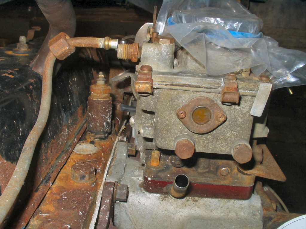
Water pump/thermostat housing
Fuel Line/carb nuts
Oil filter/carb brake/clutch lines
Oil Pressure Regulator
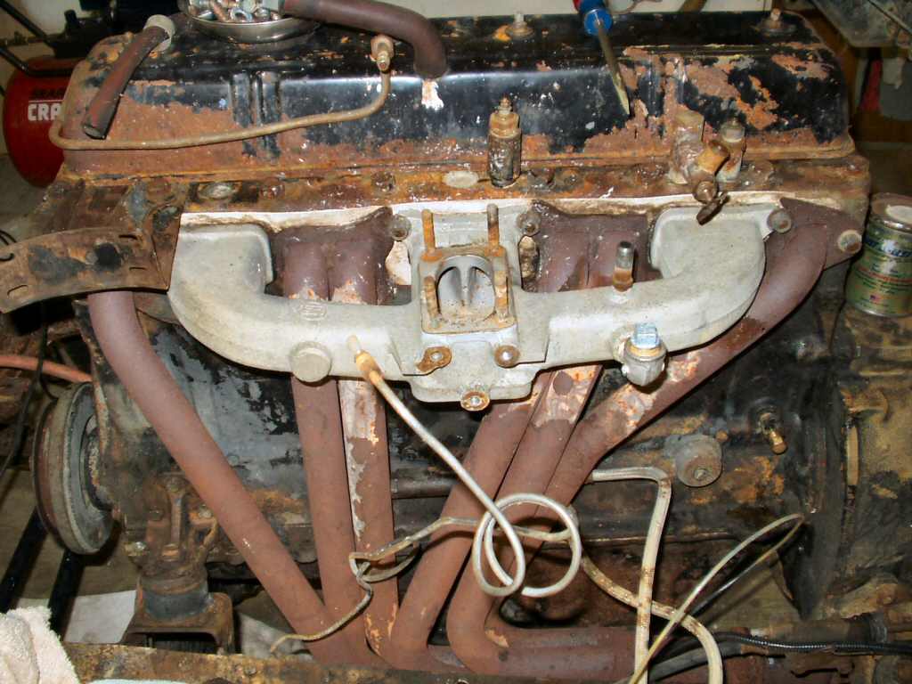
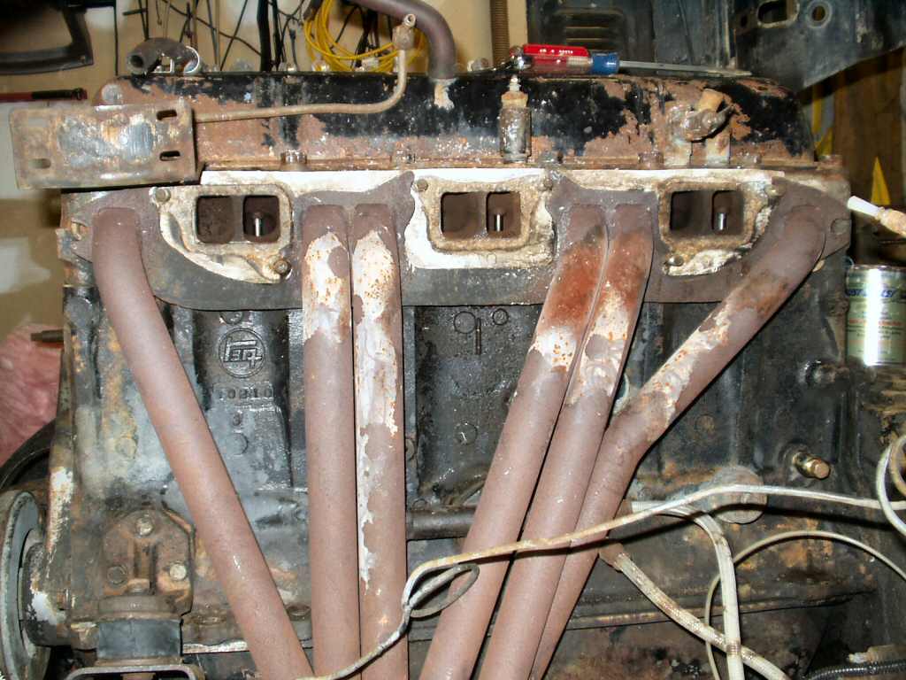
Intake/exhaust nuts/washers
Headers
Fuel Pump
Starter
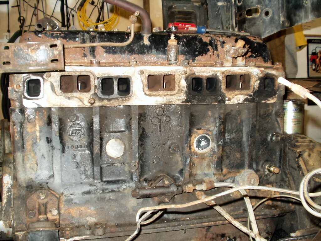
Once I had all the parts removed they were cleaned,
painted or powder coated then stored wrapped in paper until I start putting
it back together.
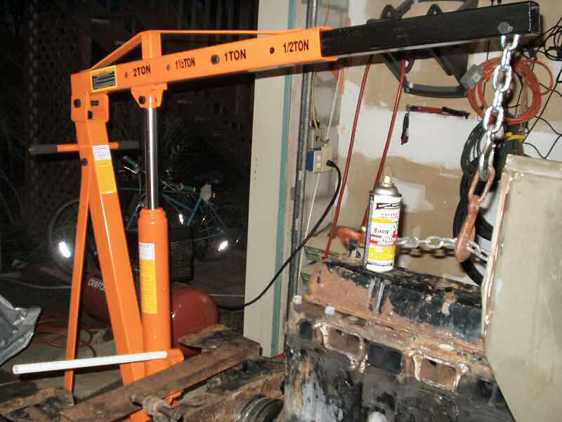
I bought a 2 Ton engine hoist (See Fig.
7) and 1000 lb stand from Harbor Freight See (Fig.
8). It was money I did not have to spare on this project but I justified
it by coming up with 'other' uses for the hoist. Plus I have read that it makes
it easy to replace transmissions and T-case's! I also bought 4 12mm x 1.75 x
100mm bolts for the stand. (Turned out 100mm is WAY too long! Measure first
before ordering bolts!)
Fig. 9
Chain Too Short!
Fig. 10
Coming up and...
Fig. 11
Almost...
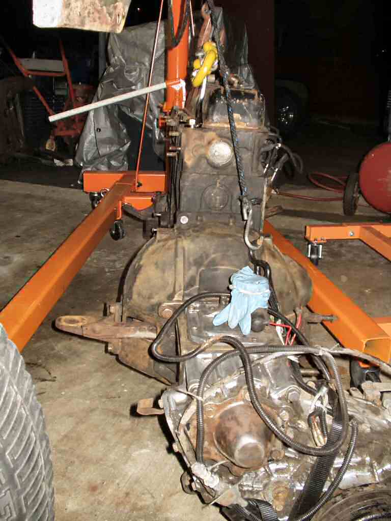
I decided to pull the engine, tranny, t-case as
one unit since I did not have to worry about the body. Plus I wanted to see
how the HF hoist handled the worst case scenario of all that weight. HF did
not have the engine hoist leveler in stock at the time so I had to figure out
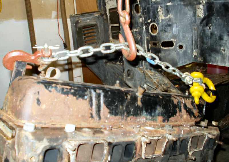
where the balance point was. I figured incorrectly! Fig.
9 shows where I made two mistakes. I had finally scored both engine
hooks off E-Bay so could now more easily pull the engine. First the chain is
WAY too short! Being short causes too much sideways force on the hooks. This
resulted in the bending of the front hook! The second mistake was positioning
the lifting 'hook' in the middle of the chain. I completely misunderstood the
lever action the tranny and t-case would have on the whole assembly. Though
the motor outweighs them over 2:1, the fact they are extended out means the
balance point is MUCH closer to the rear of the engine. This provided several
moments of', "Oh Shit!"
I know, I know! Engineering 101: The Lever, right?
Bite me... First Cruiser combo I ever pulled... Did I mention I did this all totally
by myself? Yes that was also a mistake...
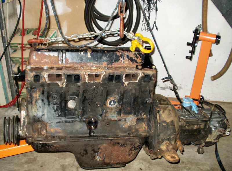
As the motor started coming up I did notice the
tilt (See Fig. 10. ) but was all excited about
pulling the engine and sort of ignored it. As the engine started to clear the
rear motor mounts it suddenly jumped forward and the tail end swung down! Heart
attack city I can tell you! I seriously thought the hoist had failed and jumped
sideways to 'save' myself. Remember I have a one car garage so I could not jump
far. :) Of course the hoist was fine and after getting my heart to slow down
I realized the position of the hoist hook was wrong. At this point I was committed
so I raised the hoist up to it's highest limit, attached a ratchet strap to
the tail of the t-case to help level it and pulled it the rest of the way out.
The hoist did this with very little flex. I immediately sat it on the floor
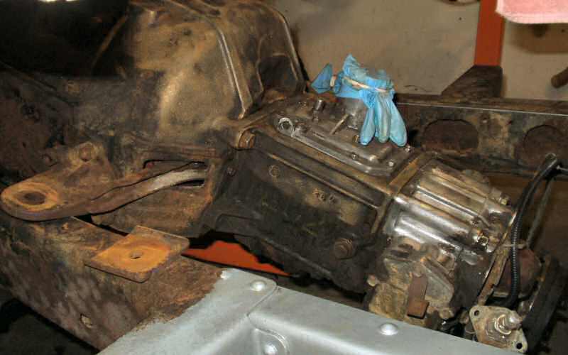
so I could reposition the chain. See Fig. 12. Now
it sat level.
Fig. 12
Finally out...
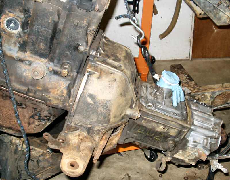
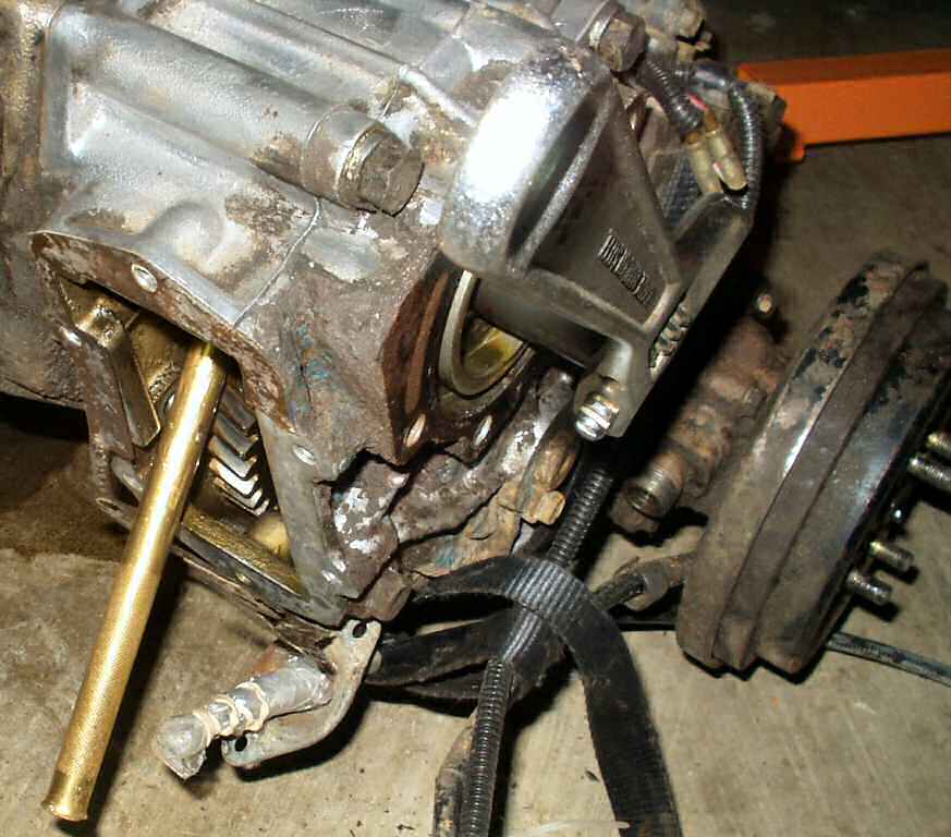
Fig. 13
Ready to pull Tranny
I gently sat the entire combo on the floor (with
most of the weight still on the hoist so as not to bend the oil pan) and proceeded
to figure out how to pull the tranny and t-case from the engine. See Fig.
13. I searched IH8MUD for tips on this (not carefully enough!), read
the FSM through a couple of times then figured it was now or never!
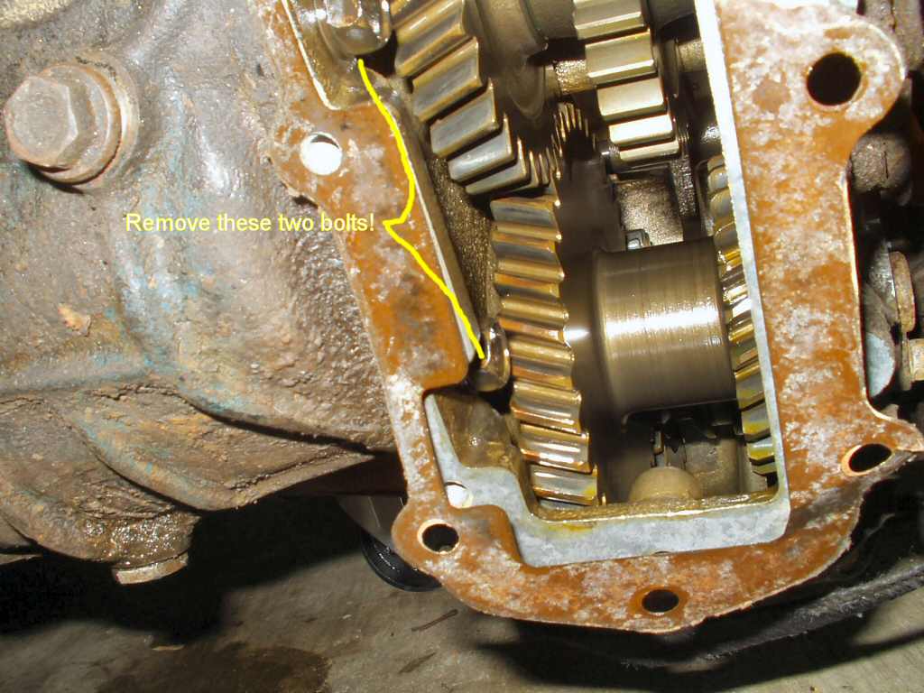
Fig. 14
Removing 'Hidden' Lower Bolts
Fig. 15
Upper Bolts
Fig. 16
Cover Off
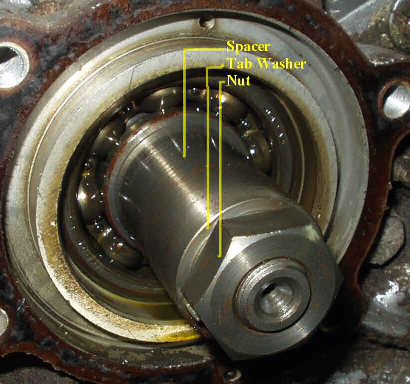
Fig. 17
Nut,Washer Spacer
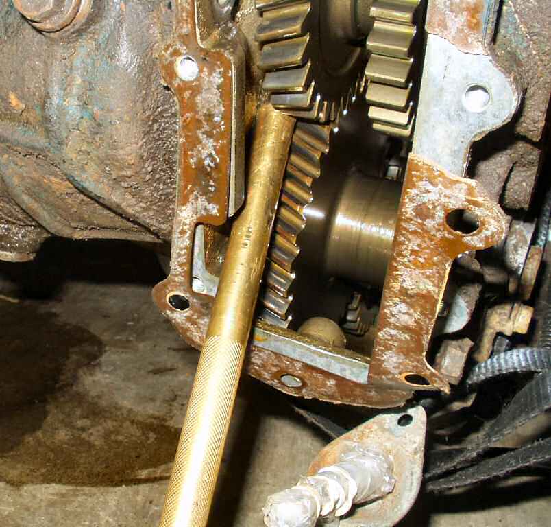
Fig. 18
Locking Gears
Fig. 19
Removing Nut
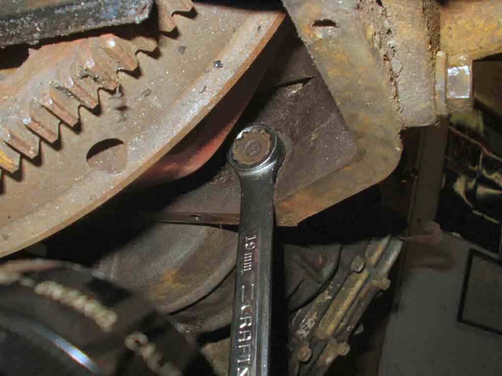
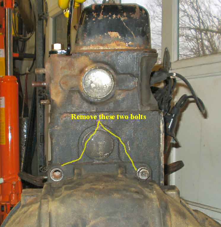
I started by removing the clutch arm from the
bell housing then removing the two 19mm bolts that are up hidden up inside
the bell housing. See Fig. 14.
Next remove the other two 19mm bolts on the
upper trans. See Fig. 15.
Support the transmission/t-case while sliding
the assembly backwards. Be SURE to support it! You don't want to damage the
pilot bearing if you are going to use it again (not recommended, they are
cheap). So now you have the tranny/t-case sitting on the floor.
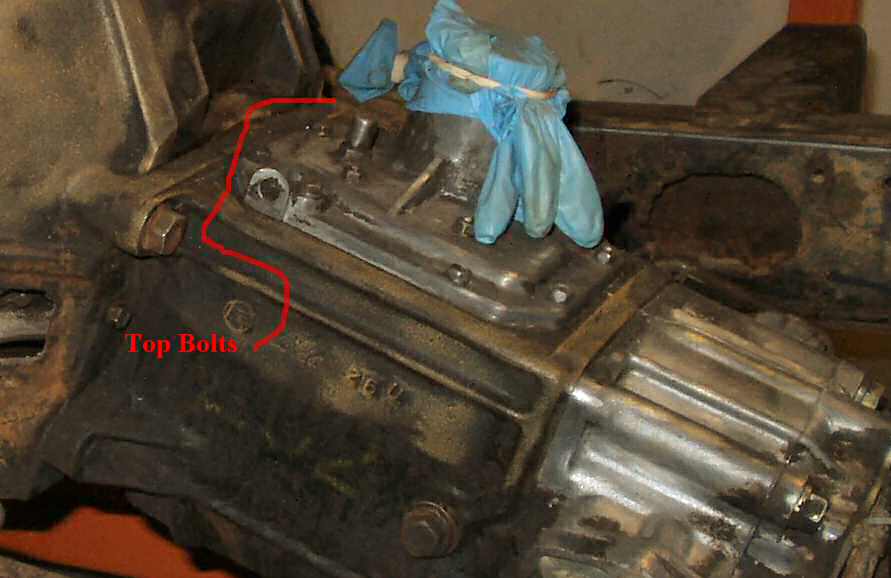
If you plan on separating the t-case from the
tranny then remove the six bolts holding the Transmission Output Shaft Cover
on AND the PTO cover six bolts. See Fig. 16-18.
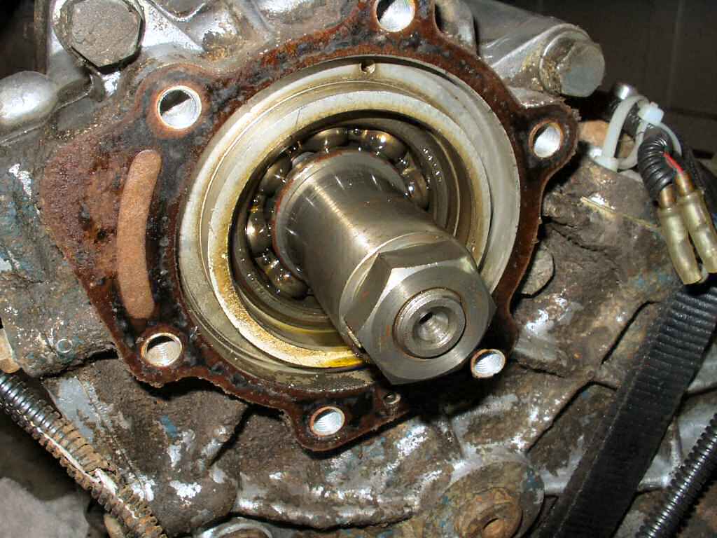
This will expose the big nut on the end of the transmission output shaft.
See Fig. 16-17.
Now refer to Fig. 18-19
and using a brass or other soft metal part (like a large brass punch) lock
the gears in the t-case so you can remove the large nut on the end of the
shaft. I used a large adjustable wrench. Place the nut, locking tab washer,
and spacer in a bag and label it!
Fig. 20
Short Inside Bolts
Fig. 21
Fig. 22
Starting the 'Split'
Fig. 23
Trouble Brewing...
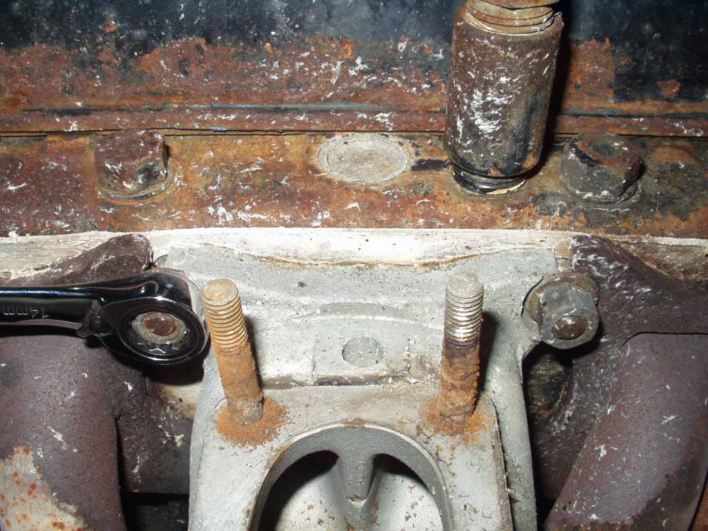
Remove the 5 bolts holding the t-case to the tranny. Start
with the two SHORT bolts inside the PTO cover. See Fig.
20. Then remove the three long bolts as shown in Fig.
21. You are now ready to separate
the t-case form the tranny.
If you are lucky enough to own the SST for separating the
t-case form the tranny then attach it now and start cranking, but if you are
like the rest of us poor slobs then you have to get creative. I'm going to
start by saying I got impatient and came up with a unique way to get'er done!
Next I'm going to tell you to ignore my method as it has some, uh, consequences!
So I had no puller, and as stated got impatient. Had I taken
the time to search IH8MUD, I would have run across an easy to build
puller but instead
I tried the brute force method of just grabbing and yanking. Of course that
did not work, it just slide about 1/2" and stopped.
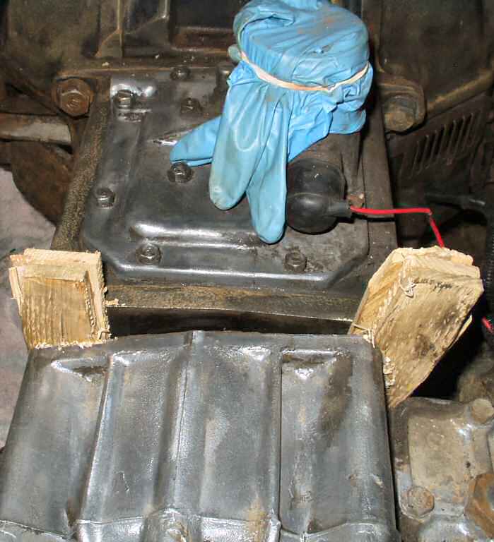
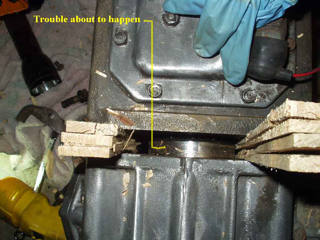
Enter the wooden shims. I had read where someone ripped a
2 x 4 at an angle and used that as a wedge to separate the two so... I searched
around the basement and found a package of wooden shims used to level things...
and without thinking through what I was about to do I inserted the shims and
started driving them in... See Fig. 22-23. (I
know all you experienced folks are laughing your asses off about right now...)
Ok long story short... About the time I was feeling real
proud of my 'solution' I heard the unmistakable sound of needle bearings
falling
inside the TRANSMISSION? WTF? I stopped pounding and then realized that as
I was driving the cases apart I was also pulling the transmission
main shaft and it's support bearing out of the rear.... Oh man....
OK so now you know. Guess I now get to learn how to rebuild a 3 sp tranny
right?
I completed pulling the cases apart and set them aside for
now. Lets get that bell housing off.
Fig. 24
Removing Clutch Arm
Fig. 25
Bell Housing top bolts
Fig. 26
Bare back...
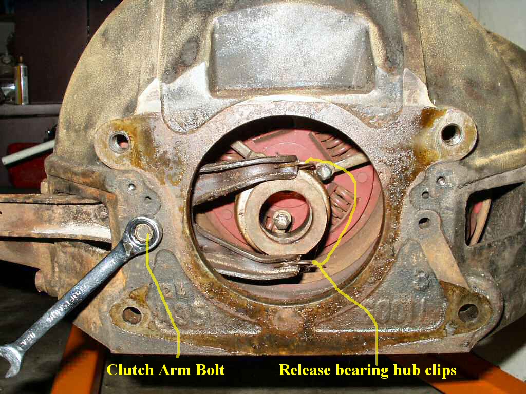
Unclip the release bearing hub (throw out bearing) clips
(See Fig. 24.) from the clutch arm. Remove the
release hub.
Remove the bolt shown in Fig. 24.
The clutch arm can now be removed.
Insert a clutch alignment tool to support the clutch.
If reusing the clutch/pressure plate/flywheel then use something
to mark the pressure plate cover to flywheel orientation so it can be installed
in the same position.
Rotate the flywheel/pressure plate cover to access the three
pairs of bolts holding the pressure plate cover to the flywheel. Loosen the
bolts one turn at a time so as not to warp the cover! Once the bolts are out
remove the pressure plate cover and clutch disk.
Next get your impact wrench and a 6 point 15mm socket. DO
NOT USE A 12 POINT!!! Flatten the locking lock washers tabs and remove the
six bolts holding the flywheel to the crank. Remove the flywheel and set aside.
Optionally remove the rear motor mounts from the bell housing.
Now remove the two bolts inside the bell housing holding the bell housing
to the engine. Remove the two top bell housing bolts shown in Fig
25 and remove the bell housing from the engine. Careful! It's heavy!
Here is what you will have. See Fig.
26. Time to get the engine on the stand.
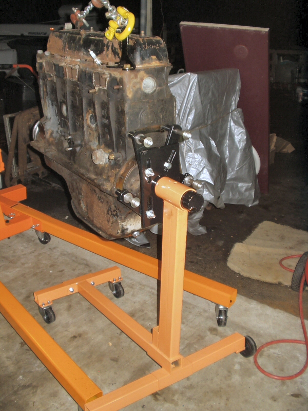
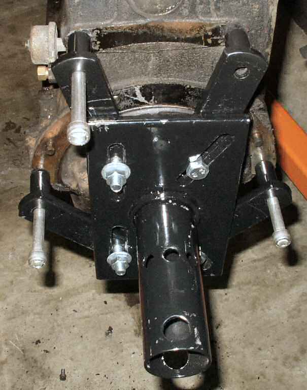
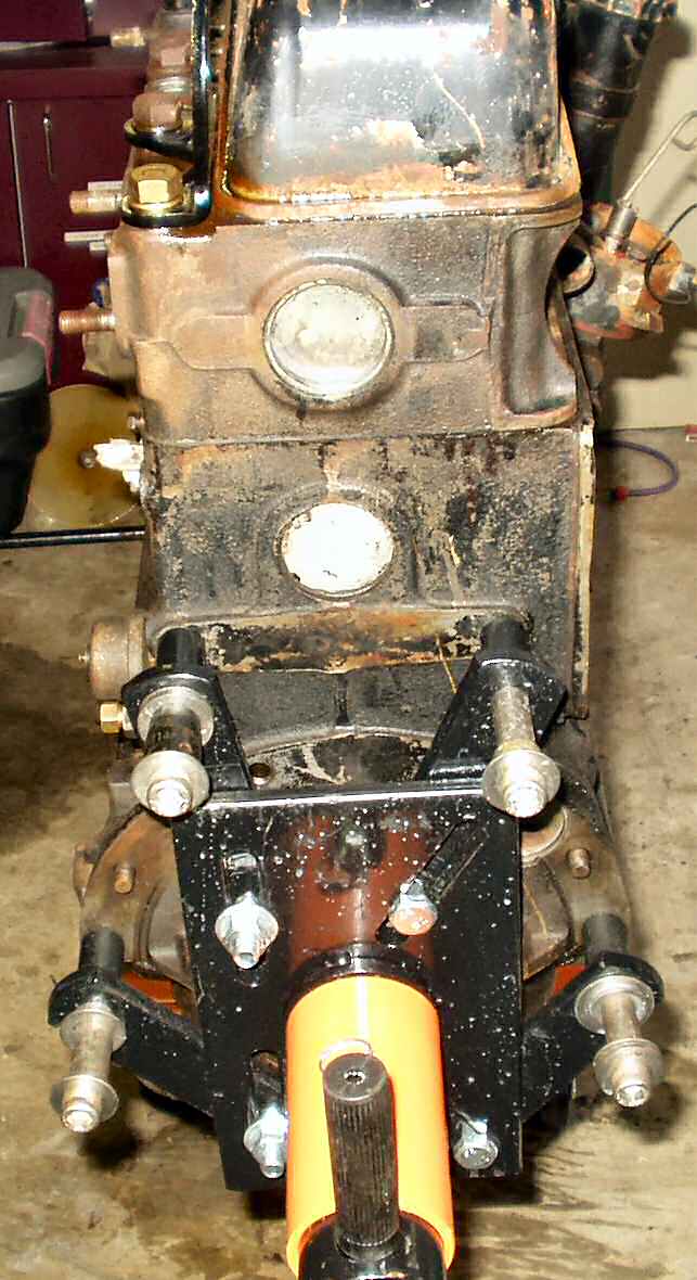
Fig.27
Mounting Stand head to engine
Fig. 28
Mounted, ready to clean!
Remove the head from the engine stand and get your bolts,washers
and spacers ready.
The idea behind a stable mounting of the engine to the stand
is to get the head arms spaced as far apart as possible left to right and
top to bottom. On a F engine that means the engine bolt holes for the bell
housing. It will take some trial and error to figure out how your stand will
work but look at the pics to see how the Harbor Freight stand works.
Remember I said I bought some bolts for the engine to stand?
These turned out to be WAY too long so I had to cut some spacers from some
tubing and use the old washer trick. Remember when mounting your engine to
the stand, DO NOT put any washers or spacers in
front of the stands arm bolt tubes! Put them behind the tubes.
You want the stress to be on the arms, not the bolts! See Fig.
27-28.