Well I spent the weekend accomplishing a major task. I got
the Engine in the frame! Lets just jump right to it... I elected to install
the engine, then the tyranny, then the t-case for reasons I'll explain later.
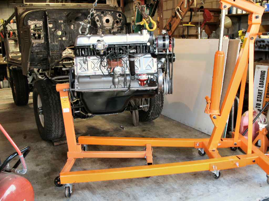
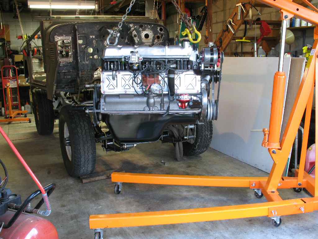
First I transferred the engine from the Harbor Freight stand
to the Harbor Freight 2 ton hoist. I set the hoist on the 1/2 ton setting
as you need as much reach as possible even with the front bumper removed.
See Fig. 1-2. Learning from my rigging mistakes
when I removed the engine, I made up a longer set of chains to keep the engine
level.
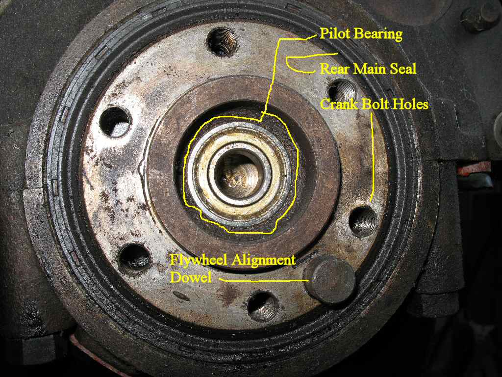
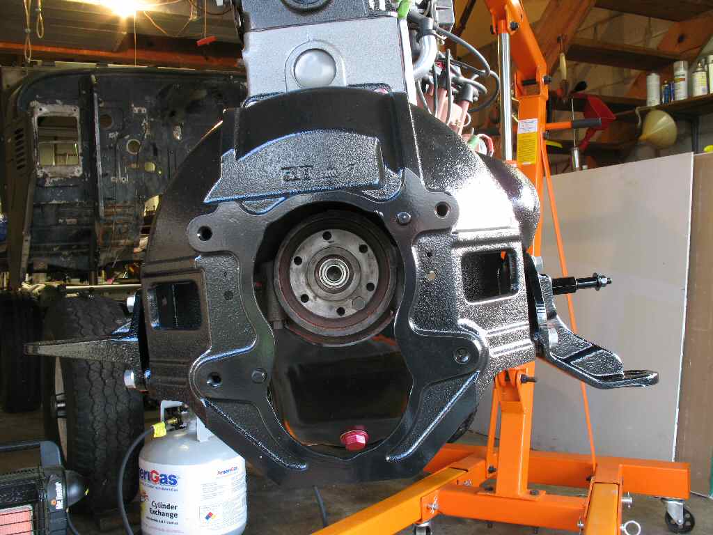
With the engine on the hoist I could now address the rear
main seal (which I should have replaced when I had the oil pan off...)
and the pilot bearing. See Fig. 3.
Fig. 4
Pilot Bearing Removal Tool
Fig. 5
Head Detail
Fig. 6
Pilot Bearing Removed
Fig. 7
Rear Seal Removed
Fig. 8
New Seal Installed
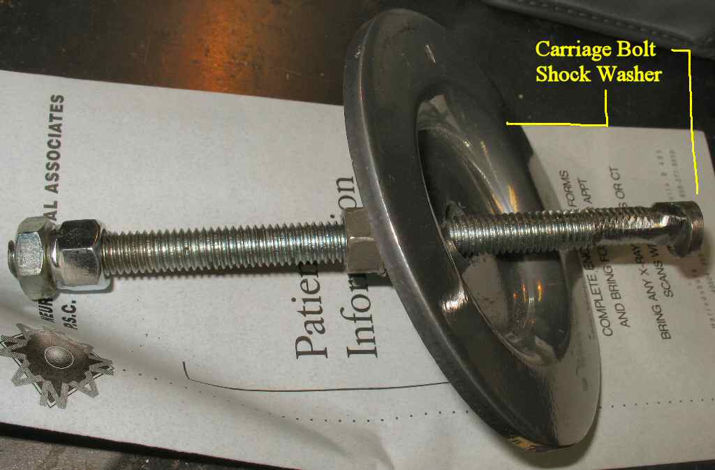
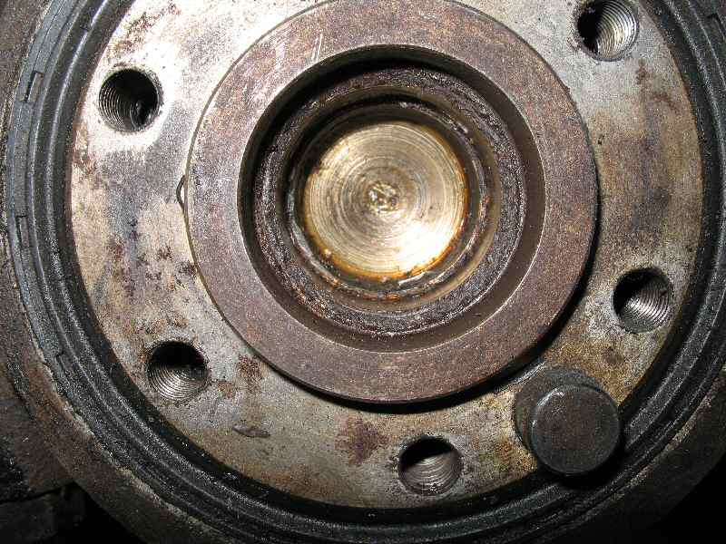
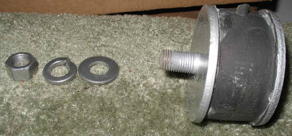
In order to remove the pilot bearing one needs a pilot bearing
puller which you can buy or even rent, or you can make one for about 30
minutes of your
time and a trip through the junk box. You will need a 4-6 inch carriage bolt,
a couple of nuts and a large socket or in my case a deep dimpled flat washer.
See Fig. 4.
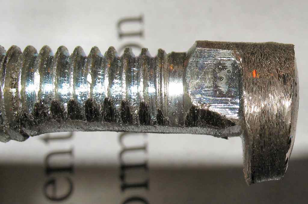
Grind the end of the carriage bolt into the shape shown
in Fig. 5. Test fit it often. It should just
go through the inner bearing race then drop down in the groove you ground
to hook over the edge.
Slide it in place, then tighten the nut and it all goes
well it will be pulled out easily. If yours is stuck, a harder, but guaranteed
to work solution is to use a Dremel tool with a small cut-off wheel to
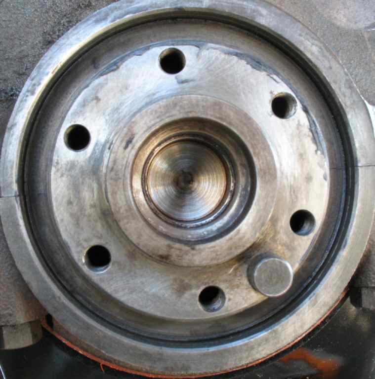
cut the bearing out. Fig. 6 shows the bearing removed.
Next I removed out the rear main seal. It was very easy
of get out. I cleaned the entire area of all crud. See Fig.
7.
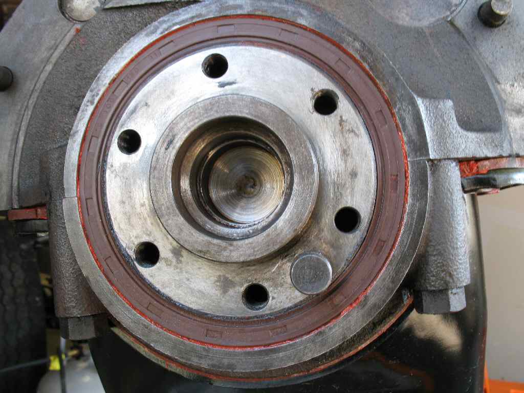
The new seal is a CCOT seal and looked identical to the
original Toyota seal. I coated the outside lip with a thin coat of high
temp RTV and coated the inside lip with grease. Using a plastic faced hammer
I started tapping it in until it seated flush with the engine. See Fig.
8.
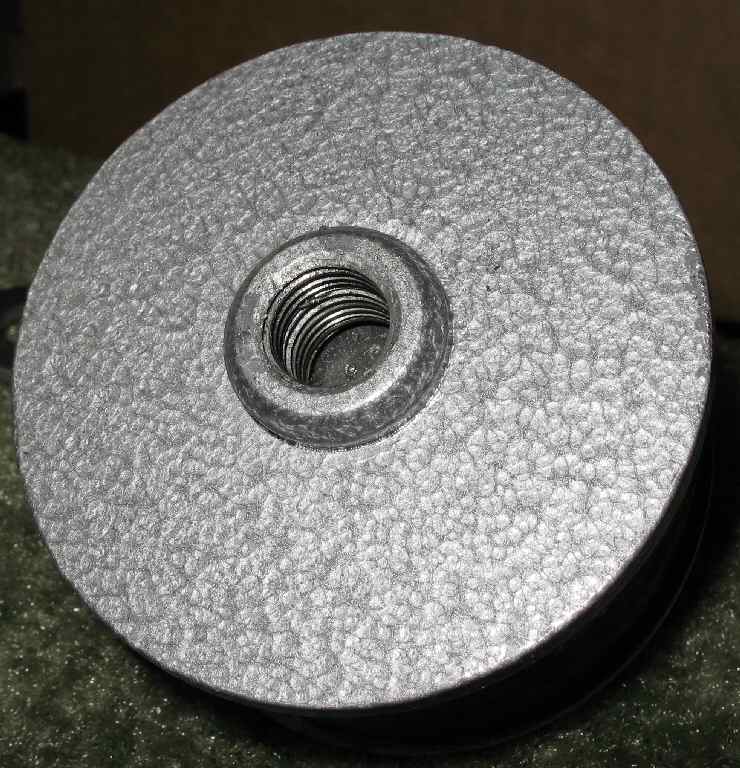
Finally I tapped the new pilot bearing in place using a
socket.
Fig. 9
Bell Housing Installed
Fig. 10
Sliding it in...
Fig. 11
Almost Aligned
Fig. 12
First Bolt In...
Drivers Side
Next I mounted my freshly cleaned and powder coated 4 speed
bell housing to the block using the 4 12mm x 1.75 bolts. These were torqued
to 54 ft lbs. See Fig. 9. I attached the motor
mount brackets to the sides of the bell housing and tightened them as best
I could. They will be torqued to spec once the engine is in the frame.
I gathered all my rubber motor mount pucks (isolators) and
bolts and laid them out on the frame then raised the motor high and started
sliding
the
hoist under the frame. Watch the shock towers and oil pan! See Fig.
10.
Everything cleared and I started lowering it down into position.
Due to the chain arrangement the engine kept wanting to twist on me. It
took a while as I was working by myself, but I finally was able to get
it close. See Fig. 11.
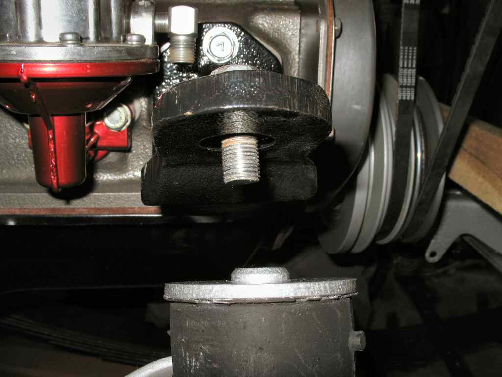
The first motor contact to the frame turned out to be the
drivers side rear mount. I got that aligned and slipped the bolt up through
the frame, into the bottom puck, up through the motor mount bracket and
finally through the top puck. A flat washer then the castle nut was installed
loosely. See Fig.
12.
Fig. 13
Passengers Side Rear
Fig. 14
Front motor Mounts
Fig. 15
Mounted brackets
Fig. 16
Aligning the front mount
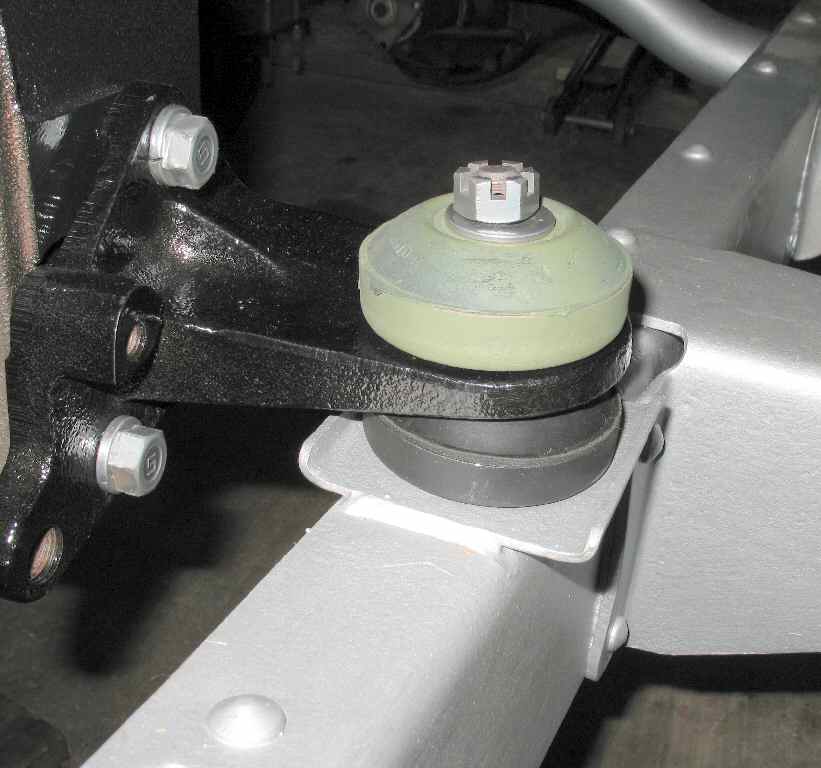
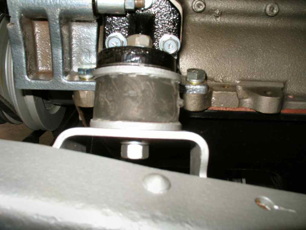
Next I wiggled the passenger side motor mount into position
and slipped that bolt down through the motor mount bracket, puck, frame,
lower puck then flat washer and finally a castle nut. Note the orientation
of the pucks for this side! See Fig.
13.
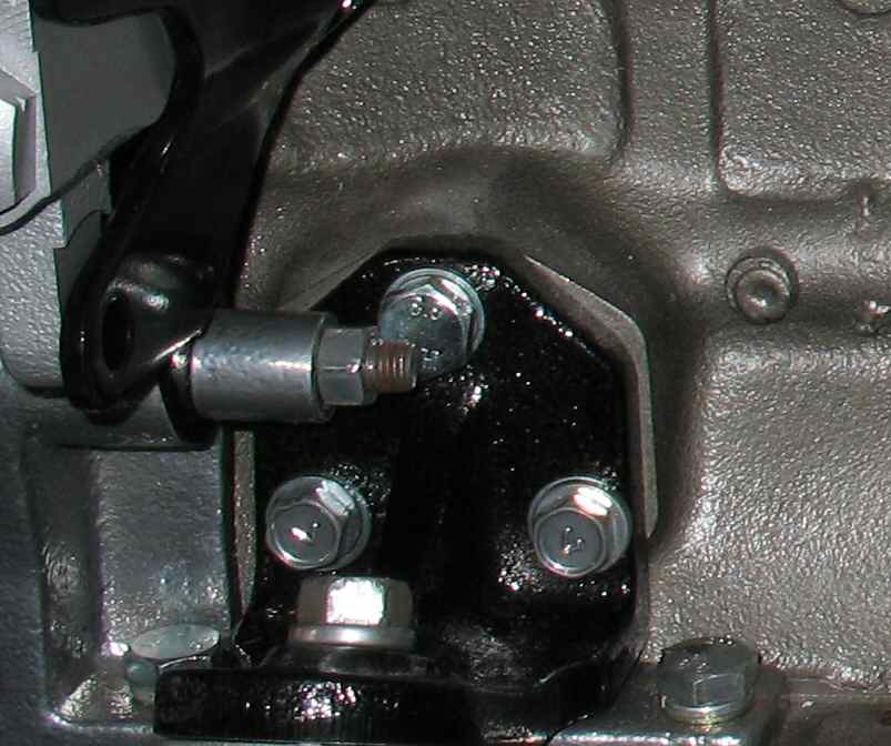
The front motor mounts are shown in Fig.
14. The stud goes
through the frame mount. I had already placed these in position with the
bottom bolt left loose so it could be moved around. The top bolt hole is
for a 12mm x 1.25 x 25mm class 4 bolt.
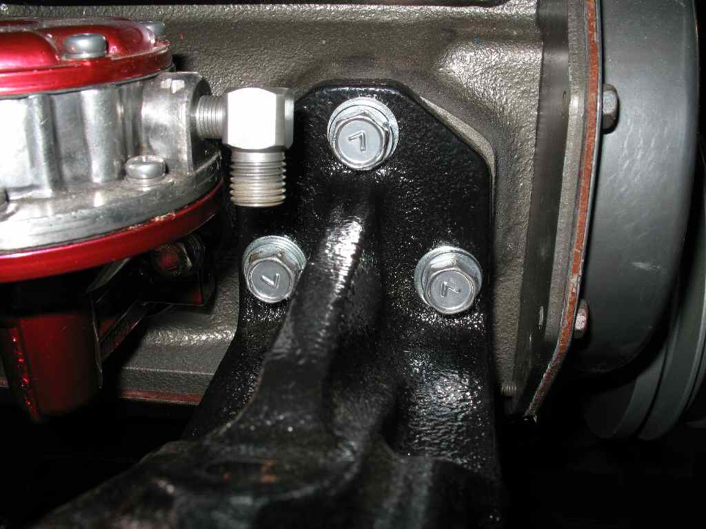
If have not already done so, install the front motor mount
brackets on the engine. Use the correct bolts! They need to be Class 7
if OEM or class 10.9 if metric. See Fig. 15.
I continued lowering the engine down until the front motor
brackets were just about to touch. See Fig. 16.
I put a bolt through the passenger side motor mount bracket
and by moving the isolator around (remember I left it loose) got it started
in
the top
hole
of the
isolator, moved to the drivers slide and
wiggled
the engine
a bit and got that one started.
Fig. 17
Complete Front Motor Mount
Fig. 18
Installed!
Fig. 19
Fig. 20
Fig. 17 shows the
completed drivers side motor mount. Don't forget to torque the lower nut
on both of them!
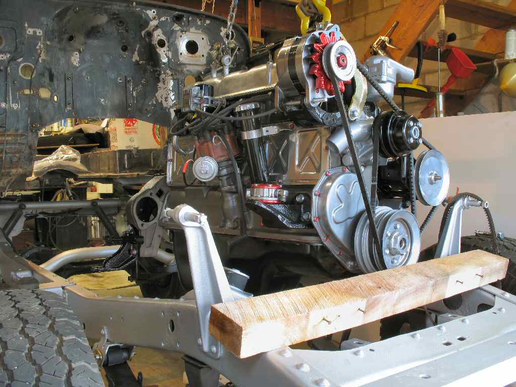
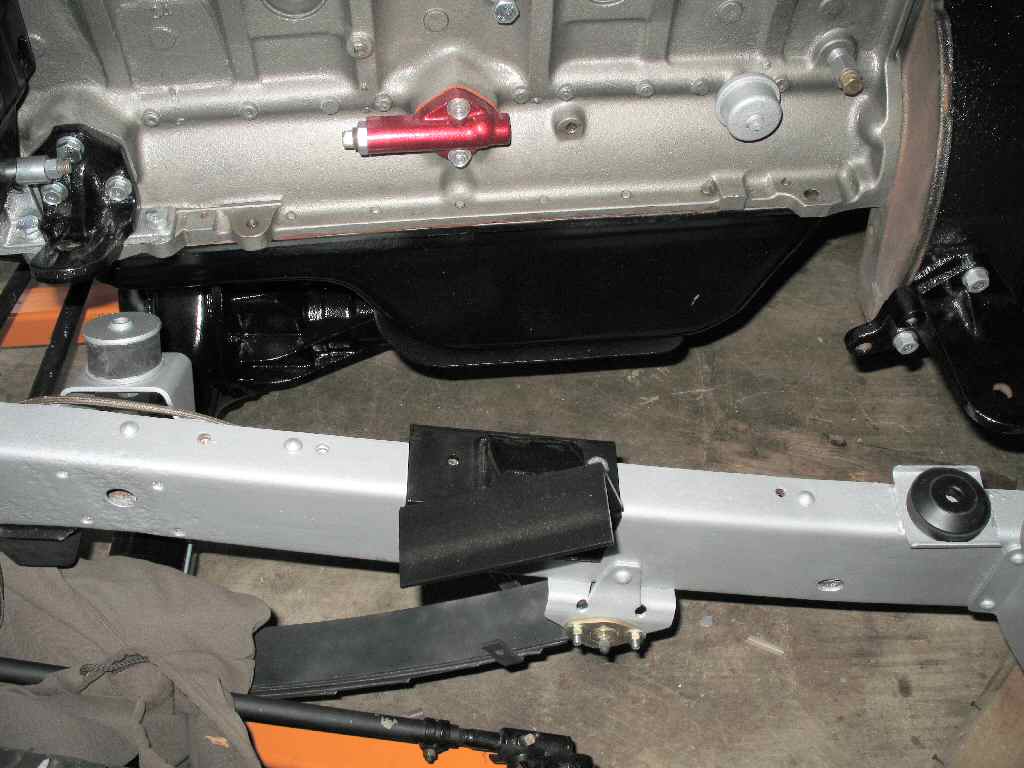
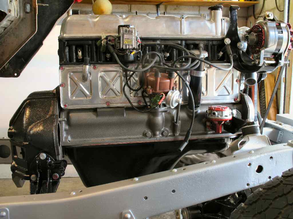
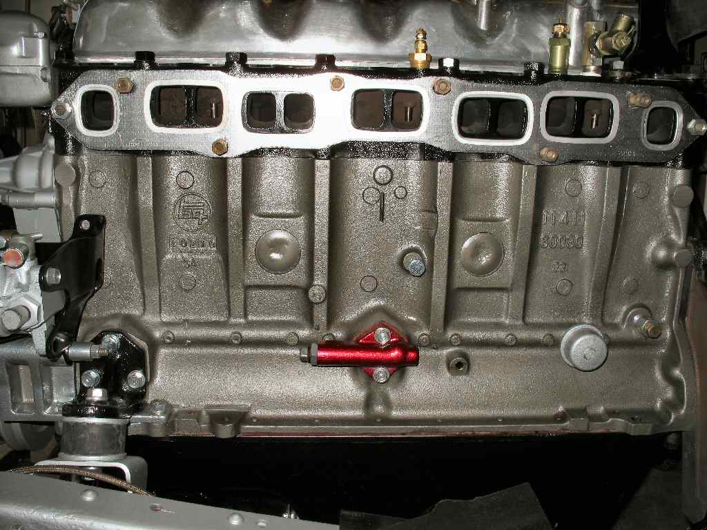
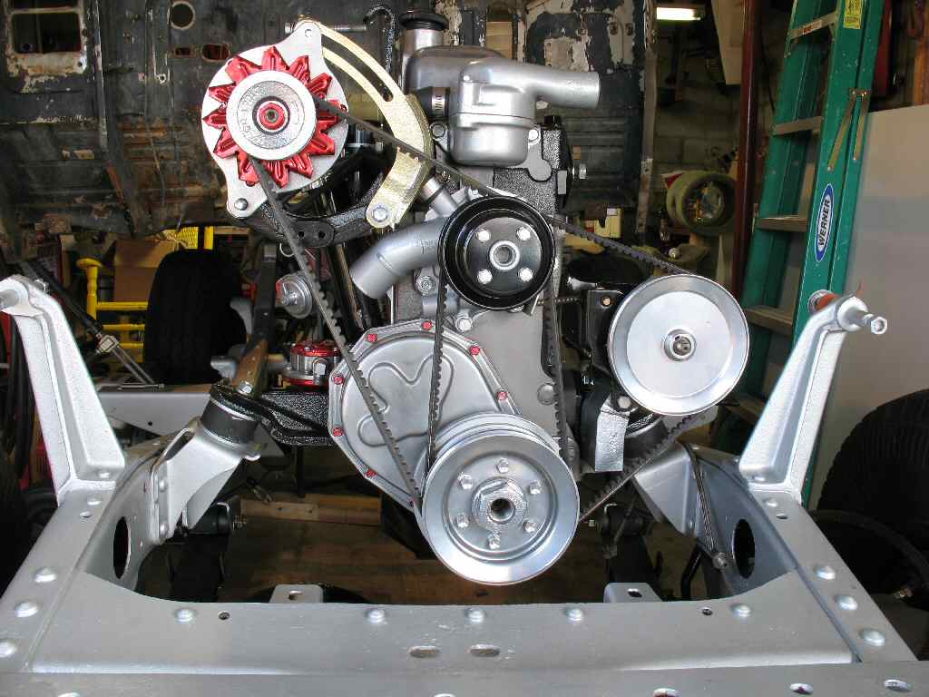
The completed motor sitting in the frame is shown in Fig.
18-20.