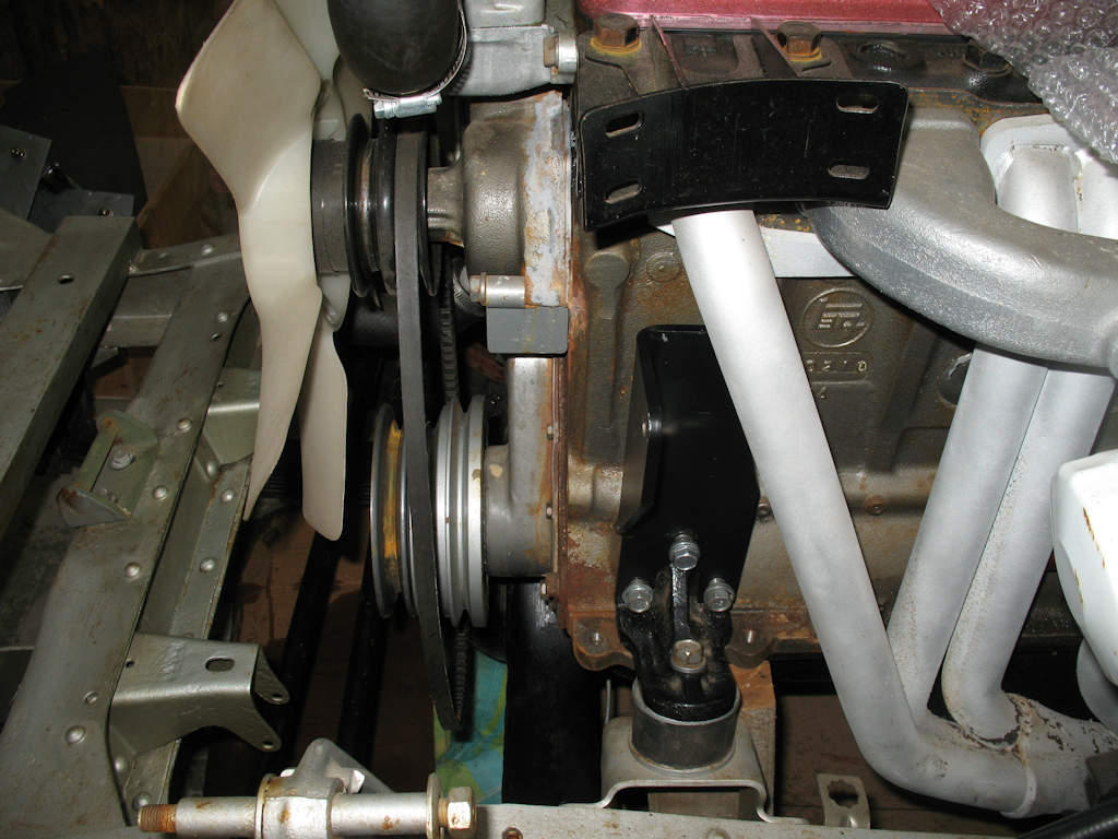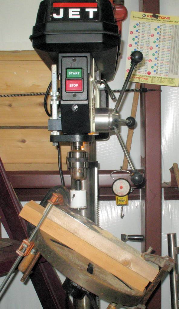
Fig. 1
What you need
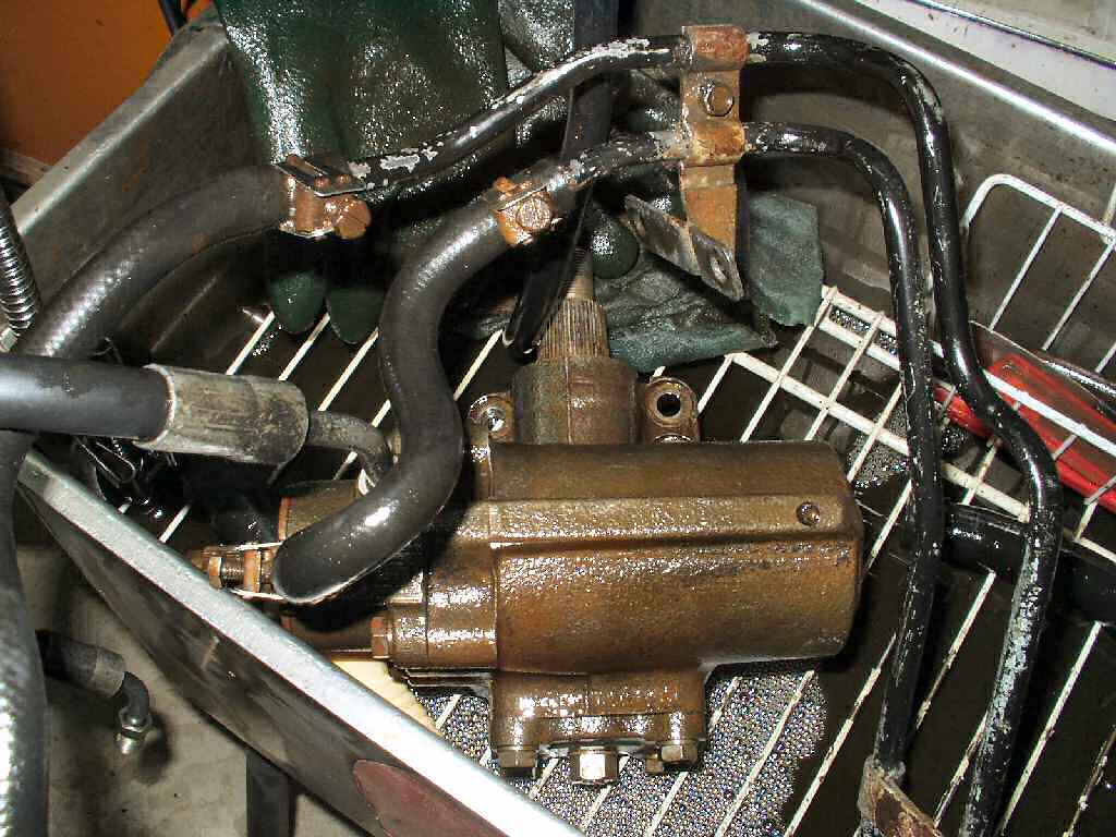
Fig. 2
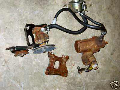
Cleaning up parts
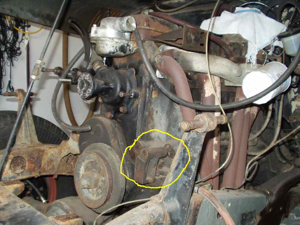
Fig. 3
Stripping the Engine
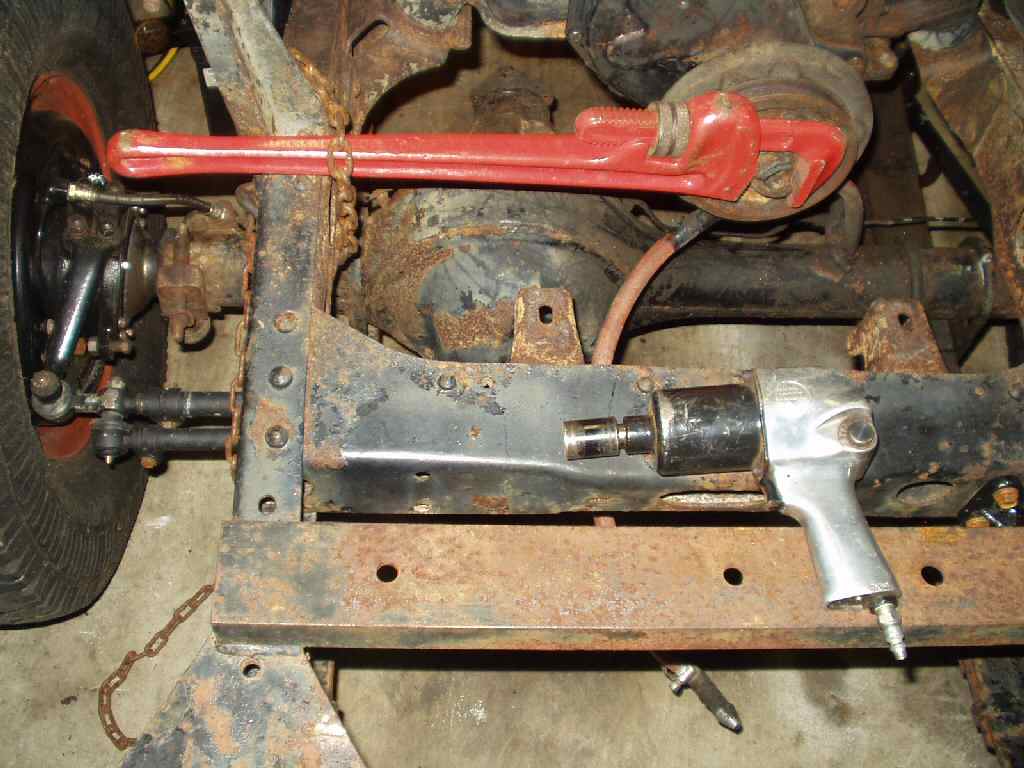
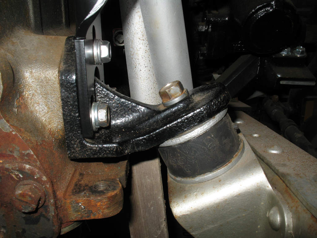
Fig. 4
Removing NUT
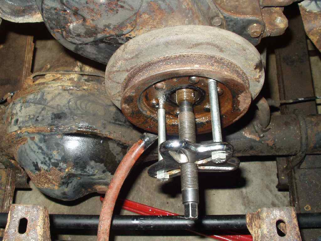
Fig. 5
Pulling the balancer
Page Under Construction!!!
I have learned a lot about doing a major project like this on the Cruiser. One thing I have learned is to research FIRST, then get ALL the parts together BEFORE tearing into it. Then make everything fit and work BEFORE painting or powder coating anything! On this particular project I didn't do this and it bit me in the ass... Not once but twice! Trust me, do as I say, not as I did! It will save you hours of time. Ok on that note...
Qty |
Description of Part |
Donor/Vendor |
Price |
1 |
Saginaw Power Steering pump |
Auto Zone #6000 |
40.00 |
1 |
Saginaw Power Steering Pump bracket |
George@Valley |
|
1 |
High Pressure Hose between sag pump
and steering box |
George@Valley |
|
1 |
Double or triple groove crank pulley
from 2F or 3F |
2F or FJ60 or 3FE |
$25 |
1 |
Passenger side alternator mount bracket/bolts/engine
lift hook |
2F or FJ60 |
$20 |
1 |
2F Alternator mounting bolt |
2F |
$3 |
1 |
** Optional 2F Alternator or 2F Alternator
Front Housing |
2F |
|
1 |
2F Water pump and gasket w/2 Groove
(NON Clutch fan) Fan Pulley |
75-78 FJ40 |
$25 |
1 |
2F Fan Shroud |
75-78 |
$20 |
1 |
Column bearing |
||
1 |
Rag Joint to fit Mini-Truck PS Box |
$29.95 |
|
1 |
Mini-truck Steering box Mount
and 4 bolts |
George @ Valley |
$99 |
1 |
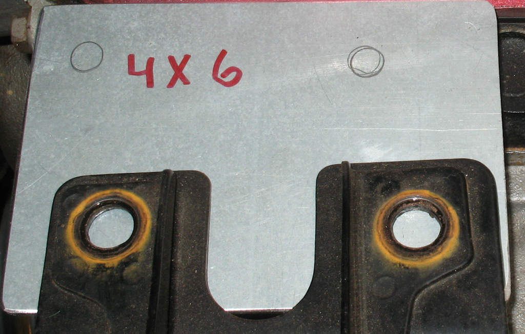
4" x 6" 10ga or 1/8"
Thick piece of steel for air cleaner bracket |
||
1 |
New belts for power steering pump/
alt/water pump. |
Vendor of choice |
$45 |
1 |
Optional Direct Drive 6/8 blade plastic
fan |
Mud Bay/Mark's
Off Road |
$10 |
1 |
1972 to 1980 Steering column and steering
wheel with KEY for ignition |
Mud Bay |
$100 |
1 |
1975 to 1971 adapter for column wiring |
Coolerman |
$21.95 |
4 |
12mm x 1.5 pitch x 1 1/4" grade
10.9 bolts to mount Steering Box to Frame |
Your choice |
??? |
4 |
12mm lock washers to mount Steering
Box to Frame |
Your choice |
??? |
4 |
12mm flat washers to
mount Steering Box to Frame |
Your choice |
??? |
2 |
8mm x 1.25 x 20mm Bolts to mount air
cleaner to adapter plate |
||
2 |
8mm flat washers to mount air cleaner
to adapter plate |
||
2 |
3/8" -16 x 2" studs or use
all thread to make |
||
2 |
3/8-16 nuts |
||
10 |
3/8 heavy washers |
||
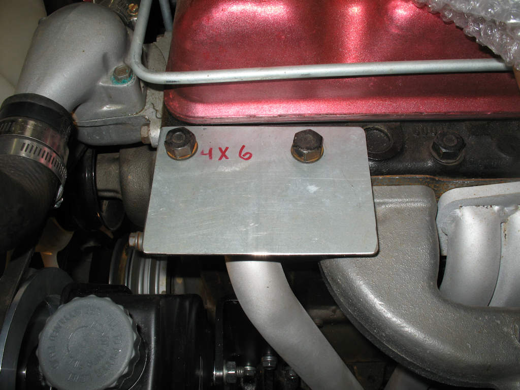
Fig. 1 What you need |
Fig. 2 Cleaning up parts |
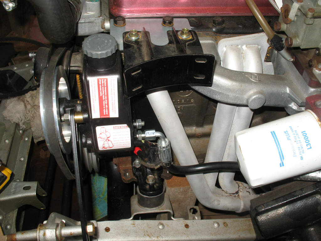
Fig. 3 Stripping the Engine |
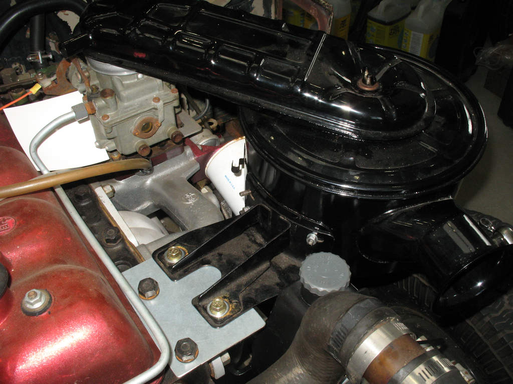
Fig. 4 Removing NUT |
Fig. 5 Pulling the balancer |
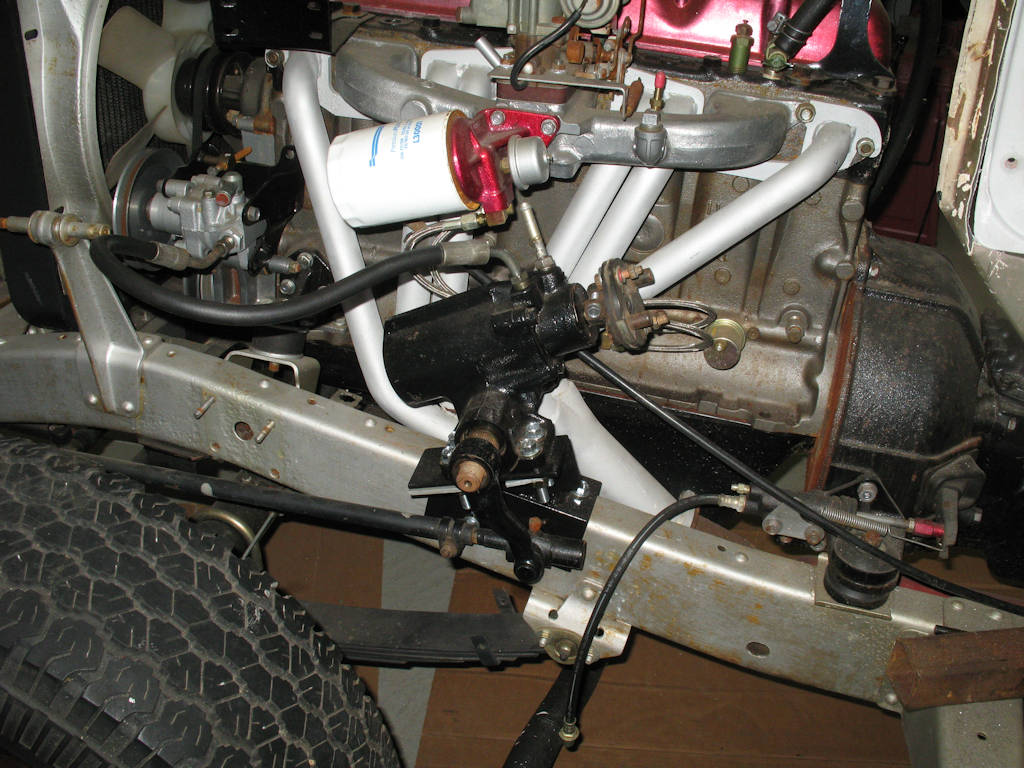
Fig. 6 Pump Bracket Mounted |
Fig. 7 On TOP! |
Fig. 8 Pump with mounting bracket stud installed |
Fig. 9 Pump with adjusting bracket stud installed.
|
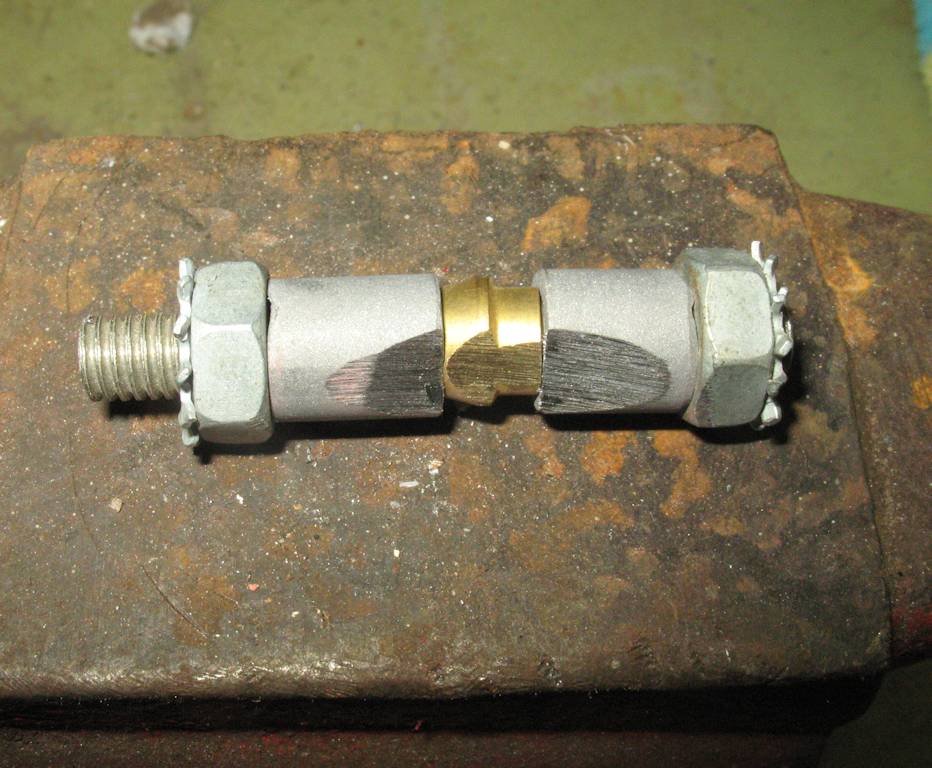
Fig. 10 Belt Adjusting Arm |
Fig. 11 Adjusting Arm Spacer |
Fig. 12 Marking head bolt holes |
Fig. 13 Plate mounted |
Fig. 14 Checking Clearances |
Fig. 15 So far so good!
|
Fig. 16 Looking good! |
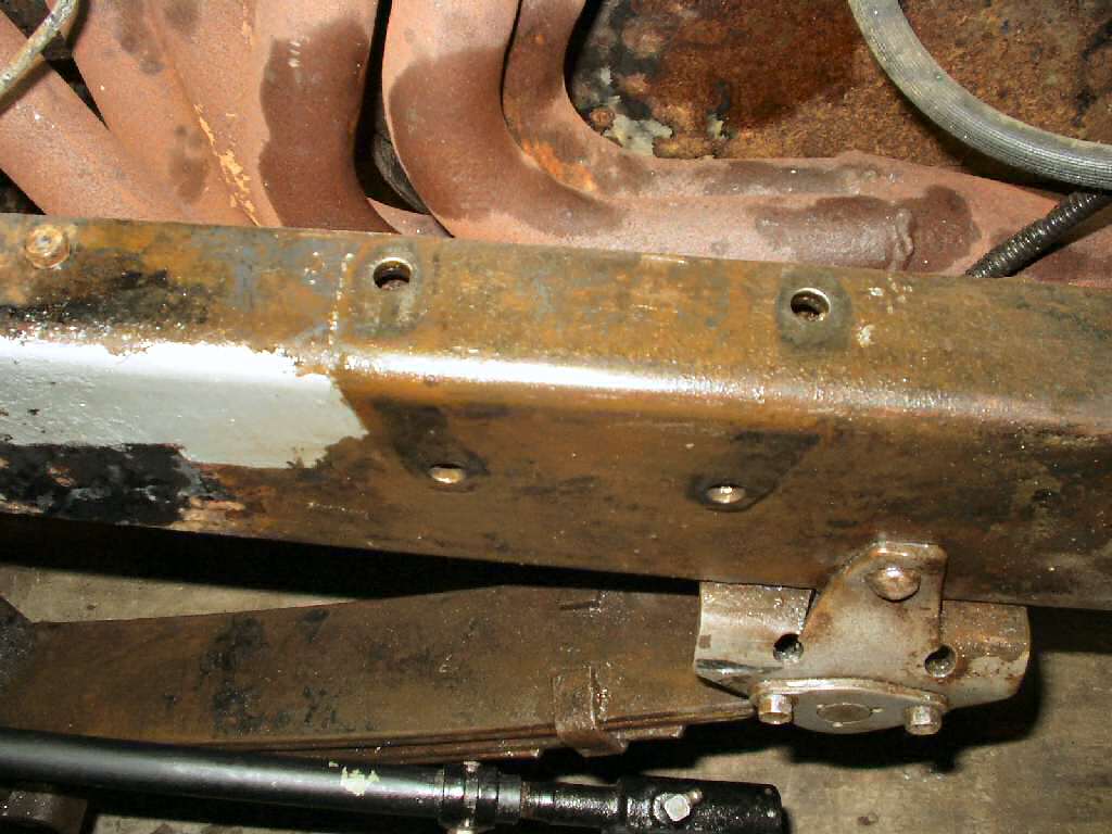
Fig. 27 Old box mount removed |
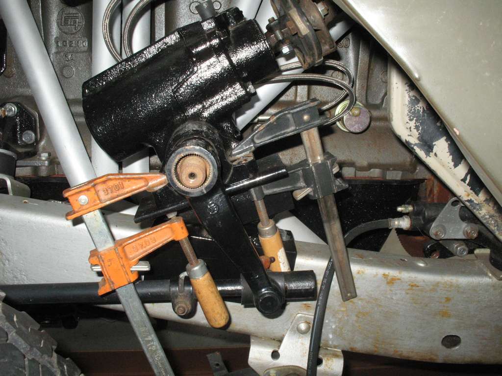
Fig. 28 Box Temporarily Mounted |
Fig. 29 End cut off 1975 Steering Tube |
Fig. 30 Mounting Bracket UNDER Dash
|
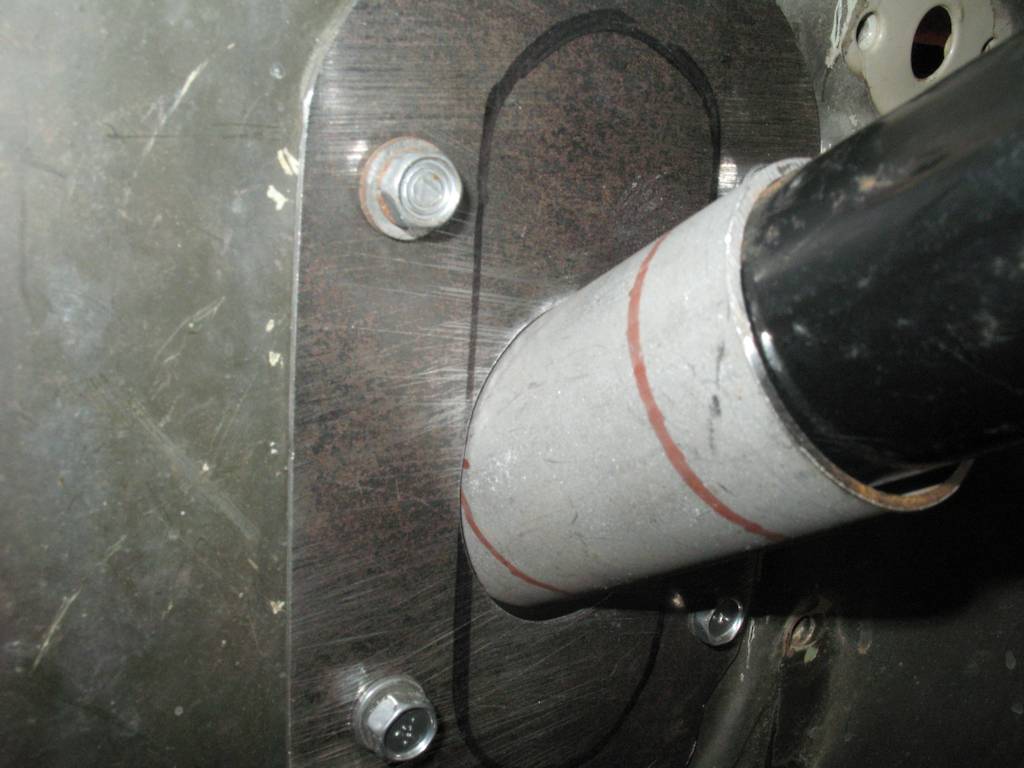
Fig. 31 Slight misalignment |
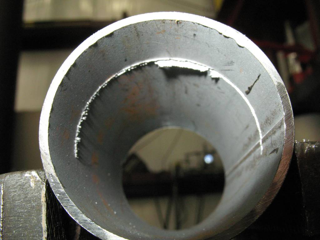
Fig. 32 Centered shaft |
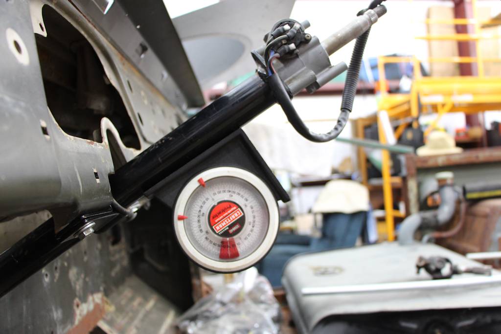
Fig. 33 Final Angle = 31.5 degrees |
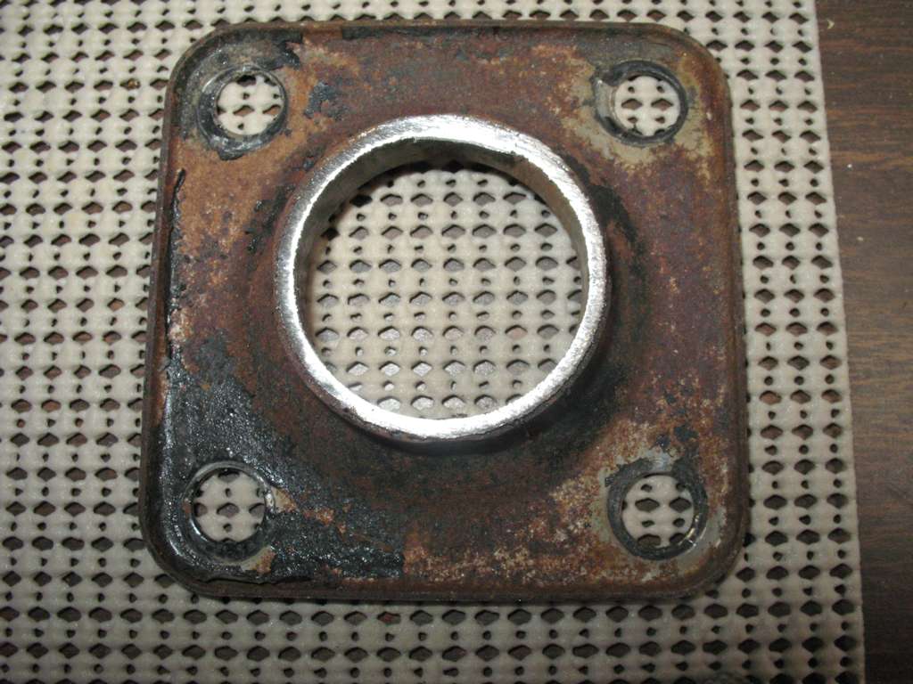
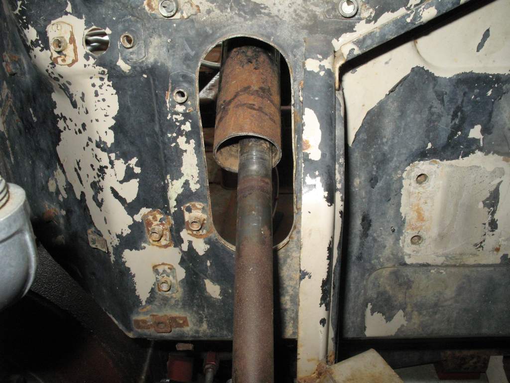
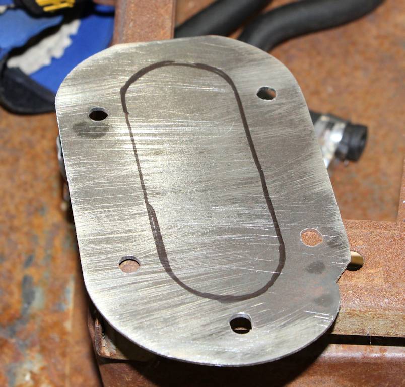
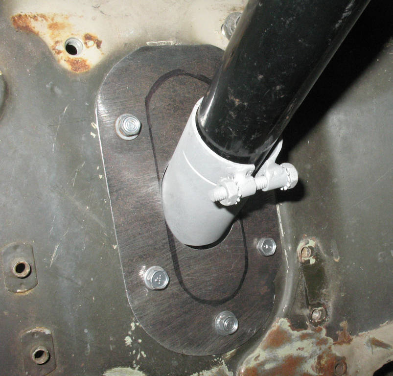
Fig. 34 Firewall Plate |
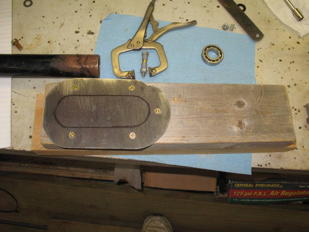
Fig. 35 Plate Attached to Board |
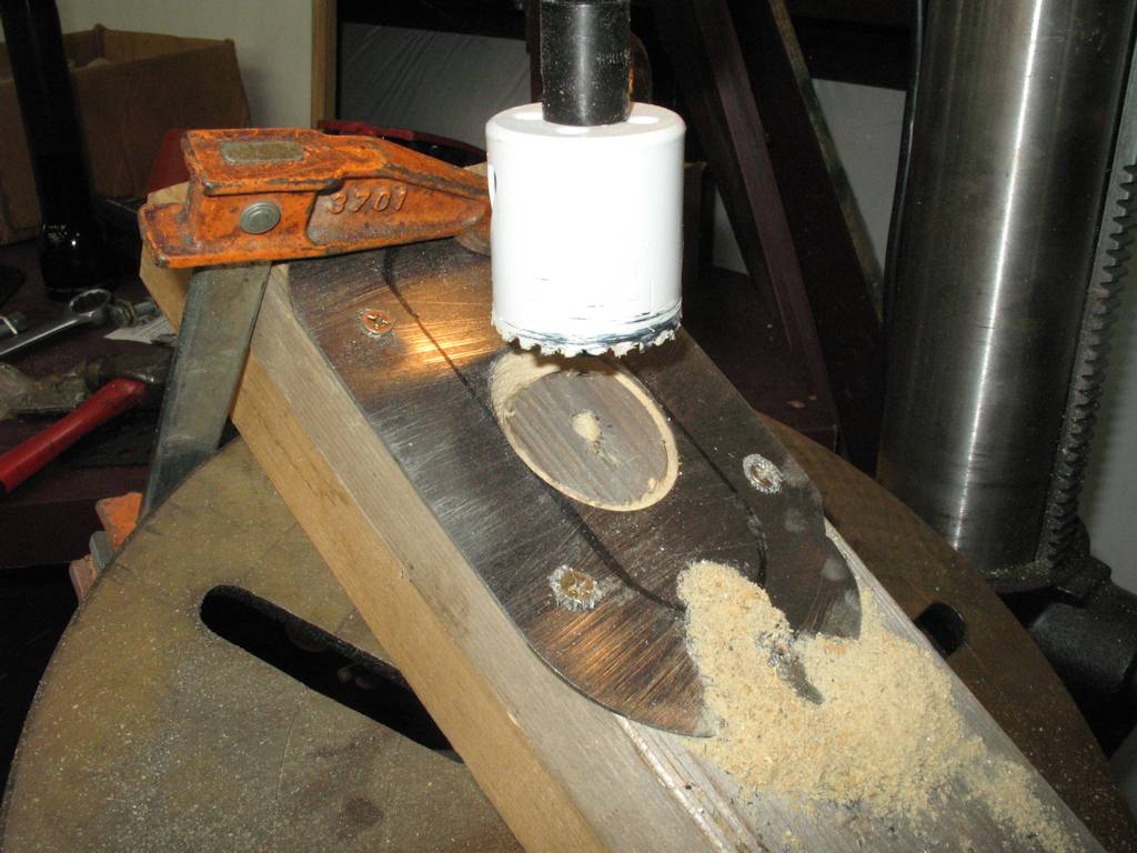
Fig. 36 Setting up the drill press |
Drilling the "Ellipse" |
|
Fig. 38 A bit low...
|
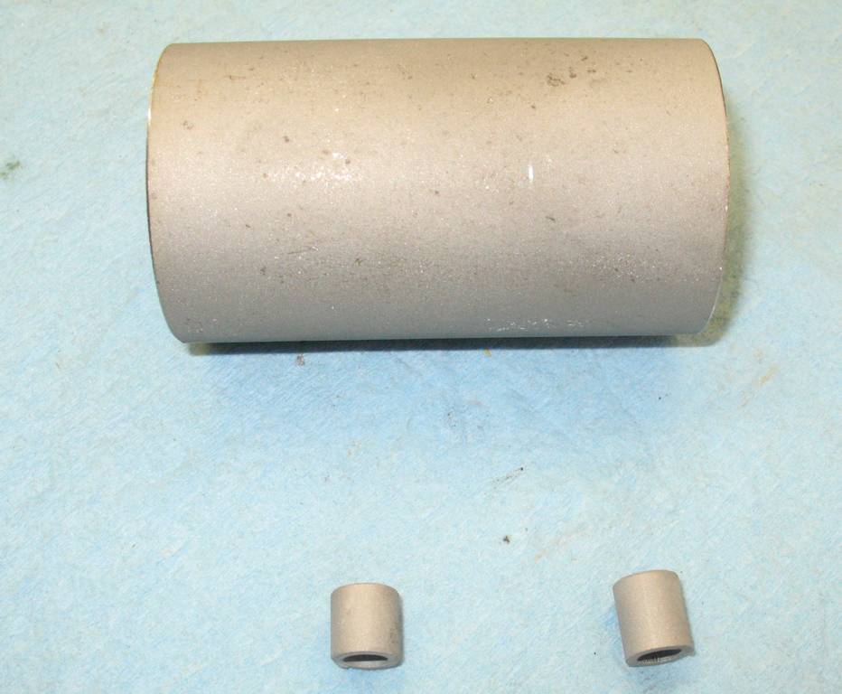
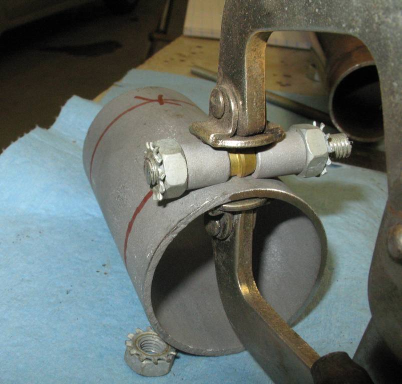
Fig. 39 Tube and spacers |
Fig. 40 Placement |
Fig. 41 Cutting the slot to make the clamp |
Fig. 42 The clamp "Ears" |
Fig. 43 Ready to Weld |
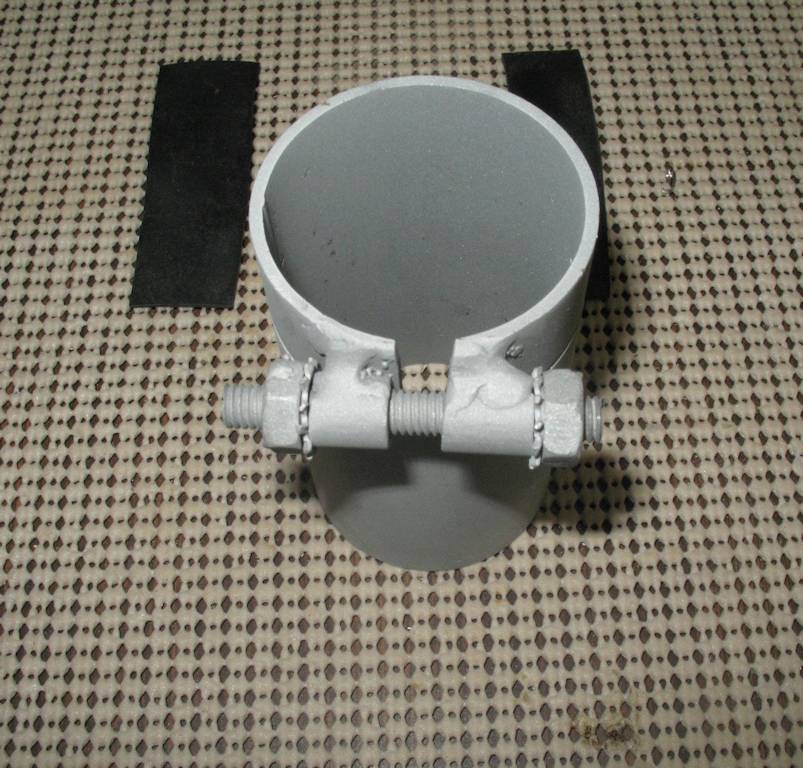
Fig. 44 Finished Clamp |
Fig. 45 How it mounts |
Fig. 46 Yes, It's Ugly!
|
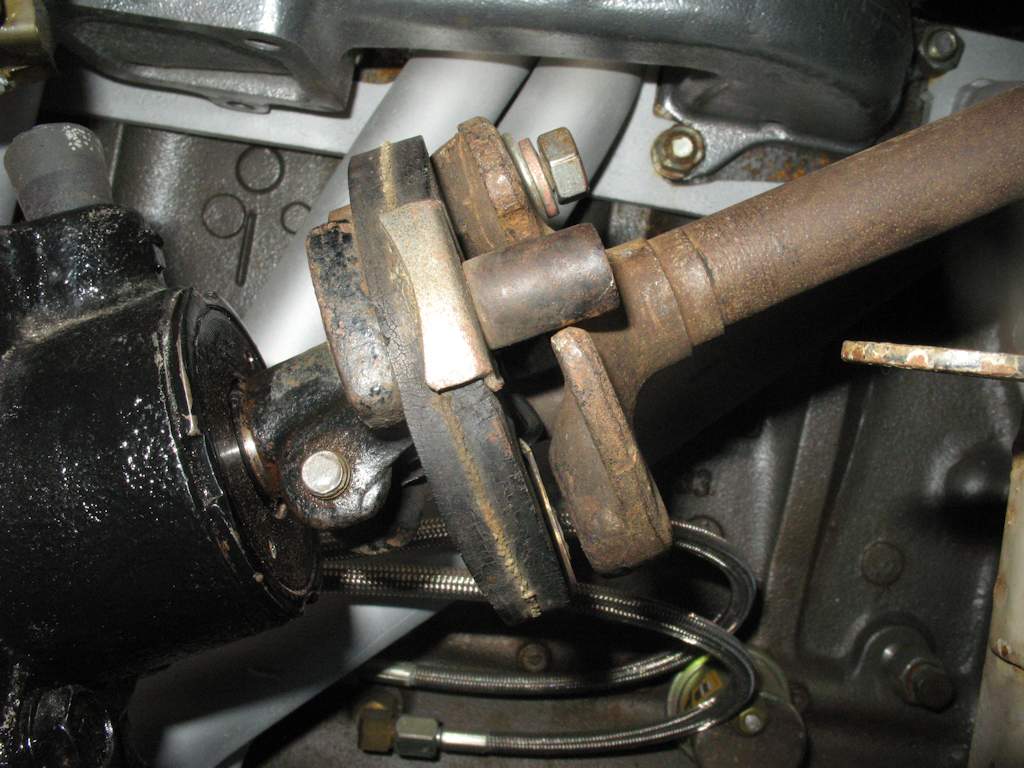
Fig. 47 Box Mounted |
Fig. 48
|
Fig. 49
|
Fig. 21
|
Fig. 22
|
Fig. 23
|
Fig. 24
|
Hosted by Global Software, Inc.
©1998 - 2023 Mark C. Baker Web Designer
Please: No part of this web site may be used without express permission... email mbaker@globalsoftware-inc.com for permission.