Now comes what I found to be the most frustrating
part of the whole disassembly: Removing the main shaft.
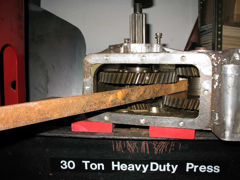
I placed the T-case
across the anvils of my shop press, used a metal bar (SST) to
support the other side of the high speed gear as recommended in the FSM,
(See Fig.
1) and started pumping... Hmmmm nothing happening...
Pump some more.... Pressure building.... then.....
There
was a very loud POP! and my heart froze.... I thought : Oh
GOD! Was that the case cracking?!!!!
Upon
further inspection I found it was just the gear releasing it's hold
on the shaft!...
Cool! Now we are getting it done! It went about 3/8" then quit...
Did I mention that this is a 30
Ton shop
press? It easily removed the shaft and bearing
from the front extension housing. It then easily pressed the bearing
off the shaft. I have used it to straighten stock Cruiser bumpers and those
are not thin! However once it moved that shaft 3/8" it would NOT move
it any further... Not knowing how much pressure the case would stand
I stopped.
Hmmmmm...... I contemplated heating up the gear
to make it release. I grabbed my Mapp torch but realized that all the
gears were covered in thick 90W... I didn't think the wife would appreciate
the smoke from burning 90W rising up through the house. (The shop is in
the basement).
So plan B. Get on IH8MUD and see how everyone
else does it. Ahhhhh..... the old beat it with a bigger hammer trick!
Well using the anvil of the press, a 3lb mini
sledge and a large brass rod and four good whacks later the shaft
slide
right
out!
I
will
never
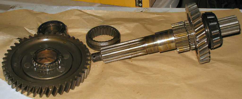
understand that.... Anyway Fig. 3 shows the
cluster out and ready for final disassembly.
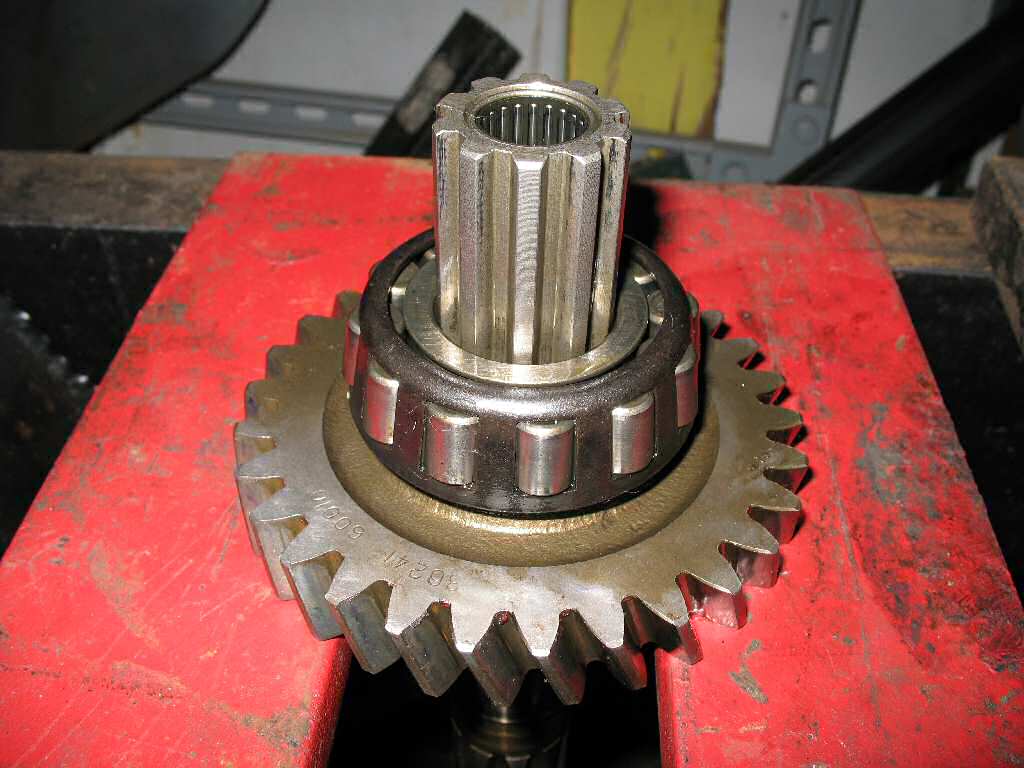
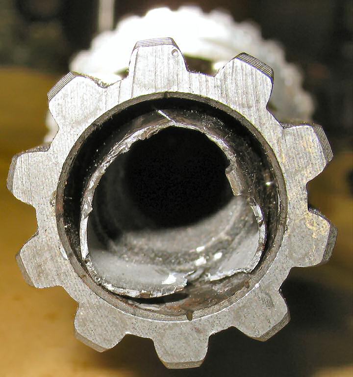
Fig. 4 shows the removal of the High speed gear
bearing. I just used the "Whack it with the hammer" method as it seems to
be the fastest. Sometimes having the fancy tools does not mean the job goes
faster...
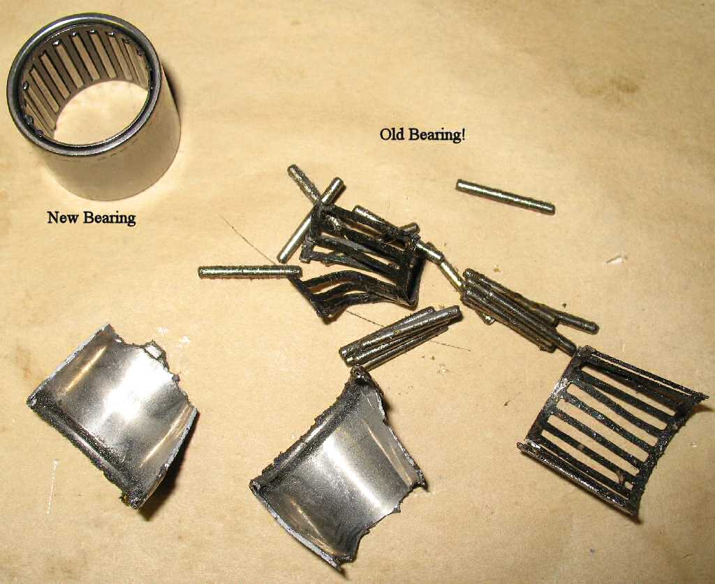
Fig. 5 shows
the butchery that occurred when I tried to pull the needle bearing from the
end of the front output shaft.
I do not have a pilot bearing puller so I first tried grinding an allen wrench
so it had a thin lip to insert into the shaft, but after an hour of
trying, it broke.
So ... break out the Dremel tool with a small
grinder wheel and carefully cut through the bearing cage, pull that out,
then cut the shell
in two places all the way through and hammer a small screwdriver behind
the pieces, then use needle nose pliers to pull out the pieces. Pain in the
ass...
Ok back to disassembly...
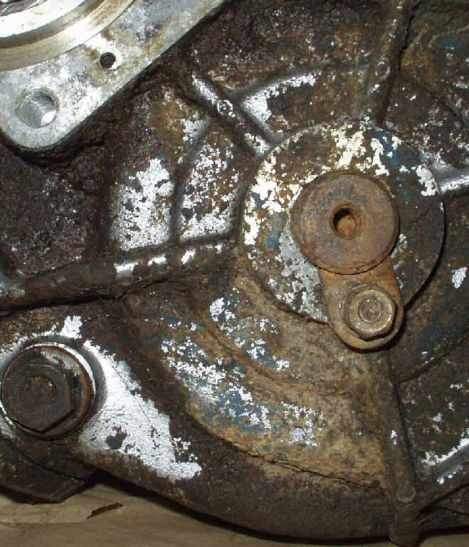
Fig. 3
Remove Idler Gear Retainer
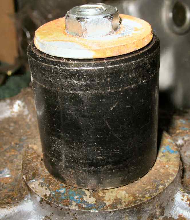
Fig. 4
Home built SST
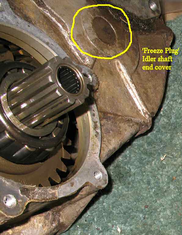
Fig. 5
"Freeze Plug"
Fig. 6
Idler Gear Parts
Remove the 12mm retaining bolt
and keeper for the idler gear shaft. See Fig. 2.
Use a 8mm x 1.25 tap to clean out the threads in the end
of the shaft.
Gather the following: A 8mm x 1.25 x 60mm or longer bolt
(cut the head off the bolt and bevel the edge) or stud, a socket large
enough to fit over the end of the shaft (I used a
15/16"),
a washer to cover the end of the socket and a 8mm x 1.25 nut.
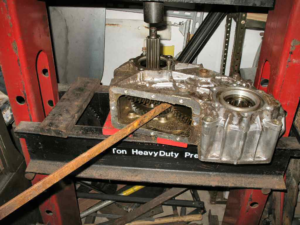
Place the socket over the end of
the shaft, thread the stud fully into the end of the shaft, place the washer
over the stud then thread the nut on the stud. Use a wrench and start tightening
the nut. As you tighten it, the stud will start pulling the shaft out of
the t-case. See Fig. 4. At this point stand
the case up so that the thrust washers and needle bearings will not fall
out of the case. You want to pay attention to where the thrust washers
and any spacers are so you can put them back on the correct side!
Note: You can also just drive the shaft out backwards a
bit to knock out the "Freeze Plug" then drive the shaft out the front. See
Fig. 5.
As mentioned note where the thrust washers and any shims
are, then lift out the idler gear cluster. See Fig.
6.
Now using a brass punch and hammer remove the main shaft
bearing race, the output shaft bearing, the freeze plug and the transmission
output seal.
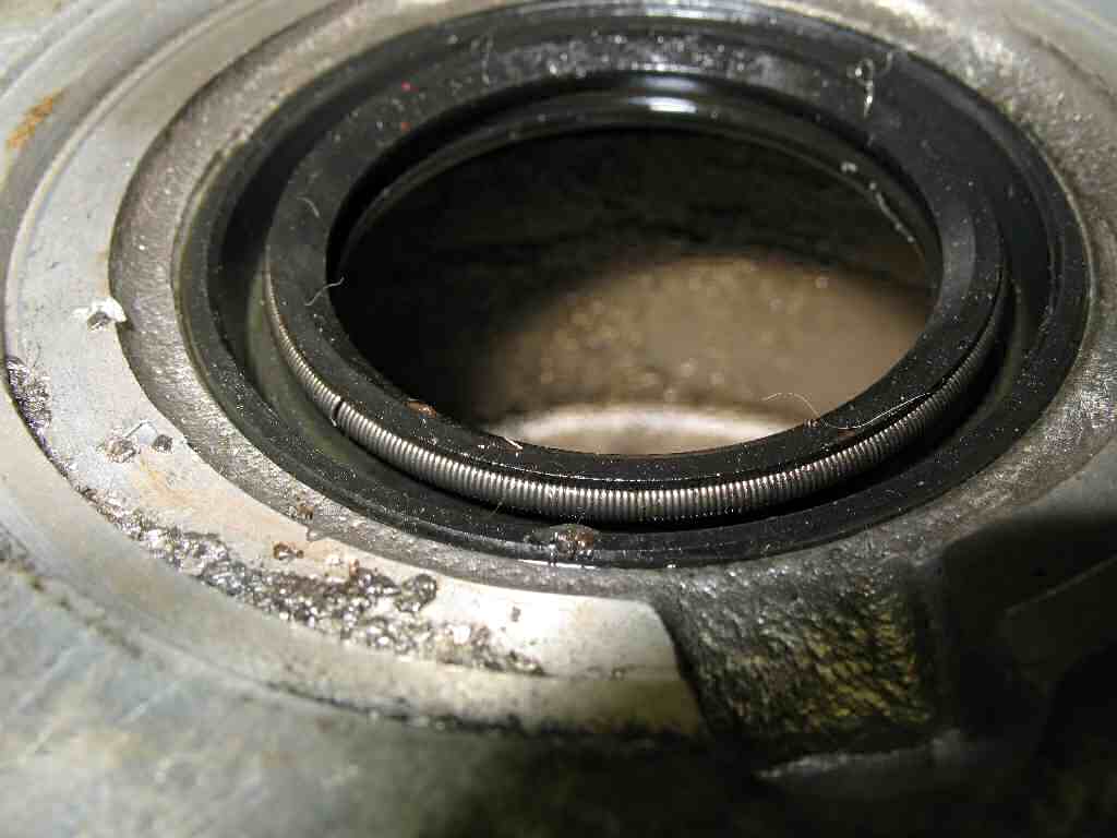
Fig. 8
Seal Orientation!
Fig. 9
Top Cover Stripping
Using a seal puller, remove the transmission seal. Caution!!!
When re-installing this seal note that it may appear to you to be installed
'backwards'. It is NOT! The spring faces toward the transmission! See Fig.
8.
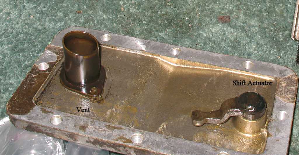
Locate the top shift cover, and pull the actuator shaft
out through the bottom. Use a punch and drive the seal out from the bottom,
it will be replaced. Unscrew the vent from the top with an adjustable wrench.
Soak it in some solvent to free it up and set it aside.
Now that the case has been stripped of all parts you can
clean it and all the covers/housings. I placed the parts in my parts
washer to get most of the crud off , then put them in my powder coating oven
at
600 degreasese for 60 minutes
to
burn
off
the
remaining oil
and grease.