Since I had replaced the rear cross member with
one from a 1974 (See Section 11) I now had to use the newer
3 way tail lights with separate turn lights. I got a used set from Tim Jones
in Odessa, Tx for a VERY good price. He even sent me an extra pair of housings!
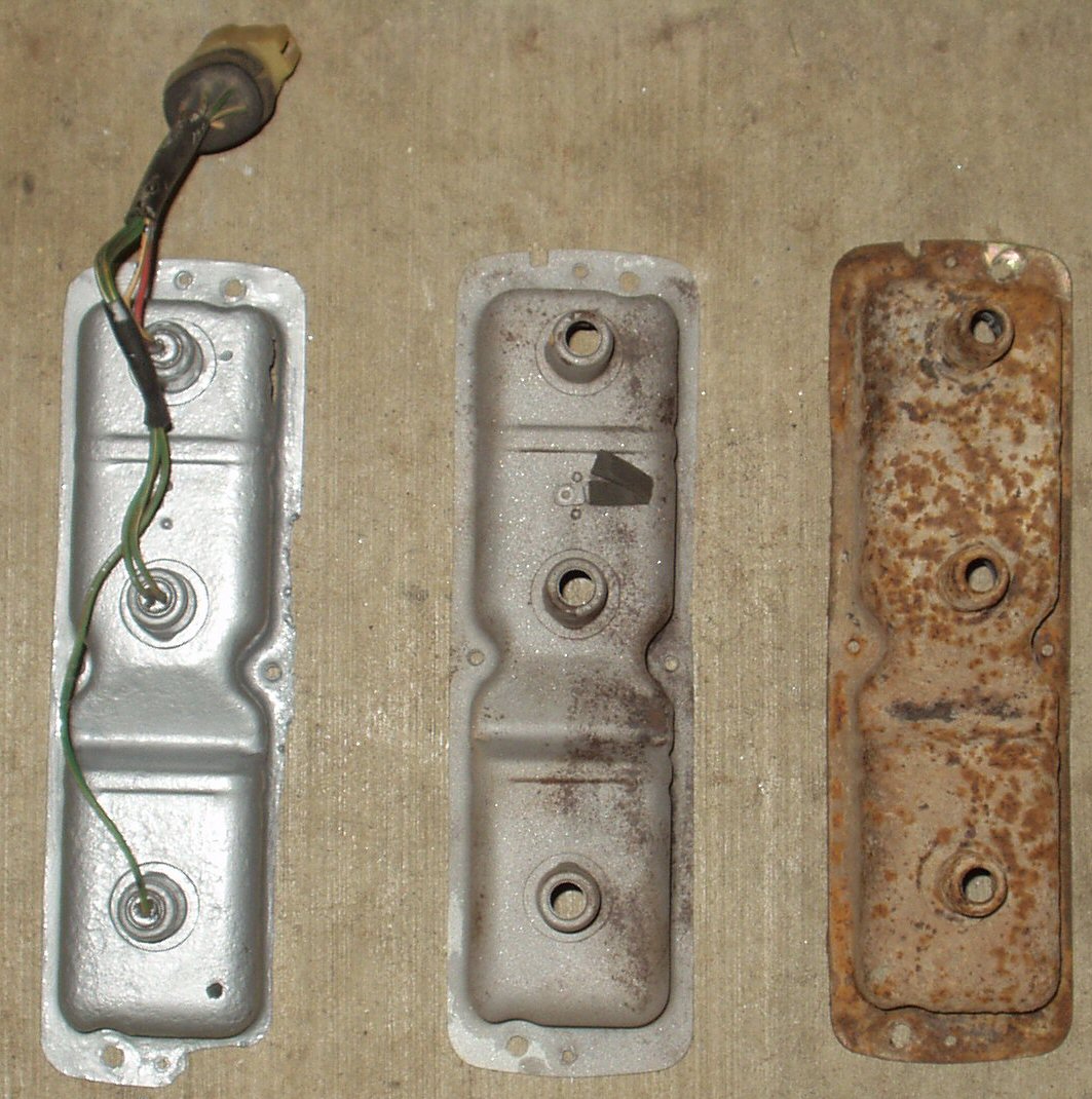
I took the best two housings, stripped out the electrical stuff, sandblasted
them then gave them two coats of rust bullet. I then rebuilt the electric harness.
See below for the transformation from horrible to serviceable.
Fig.1
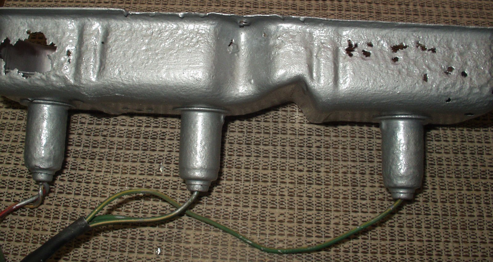
Now that I had them protected it was time to
address the rust holes ...
Fig. 2
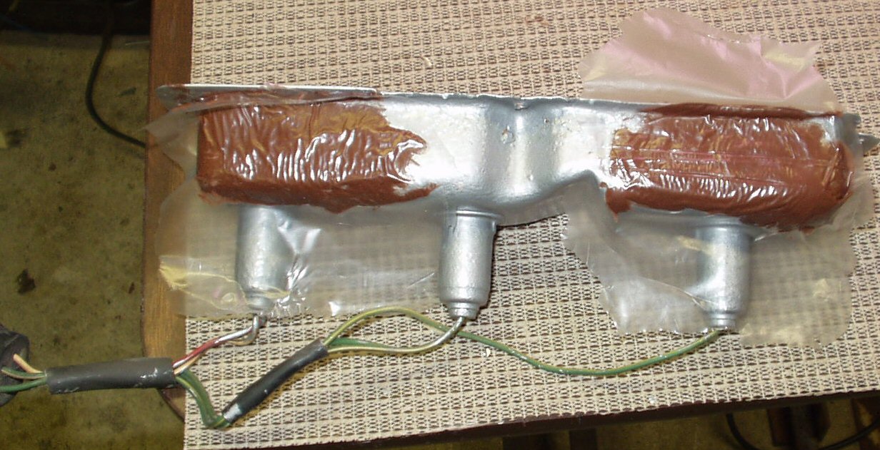
I used a fiber glass repair kit to patch the
holes in the housings (See Fig. 3), then put another
coat of rust bullet on them.
Fig. 3
Fig. 4
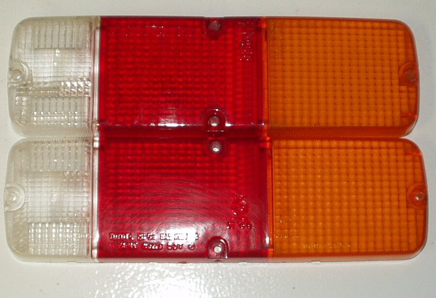
Polished Old Lenses
The lenses Tim sent ,while not broken, were very
faded and scratched. but had no cracks. I used rubbing compound and lots of
elbow grease to polish them. They turned out looking like new ones! See
Fig. 4. In case you are wondering why I didn't
use the Dremel tool? Even at low speed it would melt the plastic!
I put the lenses up until I could get a set of
gaskets. There is plenty of other work left to do believe me!
Isolating the Brake Switch from the Turn
Signal Switch
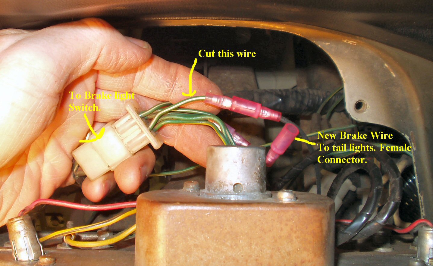
Fig. 5
Brake Harness Mods
The stock 1971 FJ40, like a lot of older American
vehicles, uses a single two element bulb to provide four functions: Park Lights,
Brake Lights, Emergency Flashers, and Turn Signals. One element is used for
the park lights and the other serves the other three functions. The newer 1974
and up FJ40's used a separate turn signal light to meet European lighting specs.
So how do we make the old system work with the
new? It's actually very simple to accomplish. In a nutshell all we have to do
is isolate the brake switch from the turn signal switch, run a new wire from
the isolated brake switch connector back to the new brake lights then connect
the left and right turn signal wires to the new separate bulbs. Just in case
someone (the next owner? ) wanted to put the wiring back the way it was I cut
the wire from the brake switch connector under the dash and crimped a male connector
on the connector side and a female connector on the other. Then when I ran the
new brake wire I crimped a female connector to it. To put it back to factory
wiring all that has to be done is unplug the new wire and plug the other two
back together. See Fig. 5.
Isolating the Brake Switch from
the Turn Signal Switch
Disconnect the battery! Failure to do so WILL result in lots
of sparks!
Take the instrument cluster loose and then disconnect the
speedo cable. Fold the cluster forward or remove it. Referring to Fig.
5 locate the large white 4 pin connector coming from the brake switch.
Cut the wire shown and crimp on a female bullet connector
to the connector side and a male bullet connector to the other side.
Run a 14ga wire from here to the rear of the truck. Crimp
a male bullet connector to this wire. Now you can go back to stock wiring
simply by unplugging the new wire and reconnecting the factory wire. For now
of course you are going to connect the new wire to the switch. Connect this
wire to each of the brake lights. Now when you hit the brakes the power comes
from the fuse box to the switch, through the switch down the orange wire and
to the lights. It no longer goes through the turn signal and hazard switch.
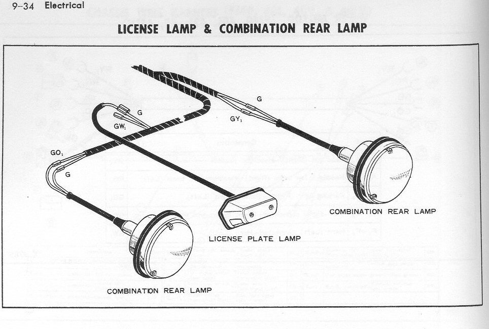
New Wiring Harness
Since my stock harness was sort of non-existent I had to create
a new one. I located the old harness running down the right frame member and
cut it back to good wire. The wires in the stock harness are as follows: a *
indicates that this is a new wire.
Wire Color
Old Function
New Function
Green
Park Lights
Park Lights
Red/Blue
Backup Lights
Backup Lights
Green/Yellow
R Turn/Brake/Emergency
R Turn/Emergency
Green/Orange
L Turn/Brake/Emergency
L Turn/Emergency
* White
N/A
Ground
* Orange
N/A
Brake Lights
The old combo lights relied on the housing being grounded through
the mounting bolts. As we all know this 'ground' tends to fail once rust sets
in resulting in intermittent lights. Toyota provided a separate ground wire
to the light housing on the new style lights to elimnate this issue.
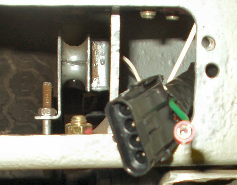
Finding stock Toyota connectors can be difficult so I decided
to just use a newer style automotive connector that is weather proof. I used
the Delphi Packard Weather-Pak connectors . These can be gotten from several
places in 2,3,4,5,6 pin versions. I got mine from Waytek
Wire. I used a 4 pin version that resembles a trailer connector. I
should have gotten a 5 or 6 pin version because I forgot about needing a ground!
I ended up using a bullet connector to provide this.
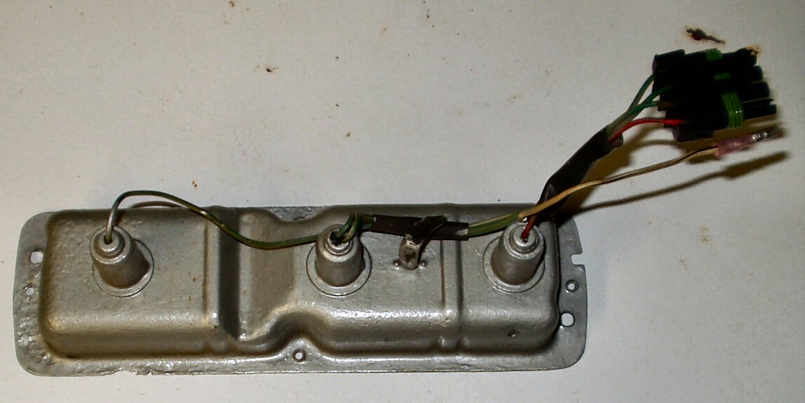
Fig. 6
New Plug
Fig. 7
Matching Socket
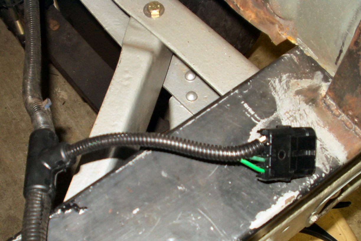
Fig. 8
New Harness
To build the new harness I cut the old connectors off of each
light and attached the new male plugs. See Figs. 6- 7.
Next I laid out enough wire to reach everything to make up the new harness.
I had to use different colors of wire but I drew up a schematic so I will know
what is what. I soldered the wires to the old harness and used heat shrink tubing
to seal that. Using 1/2" wiring loom, some cool loom 'T' connectors and
3M splice taps with dielectric grease, I designed a harness that is better than
the stock harness. See Fig. 8 for a section of
it. The hard part was the Park light circuit. That one wire has to power
5 bulbs in the rear of the truck! Two side markers, two rear lights and one
License Plate light. I used the splice taps to make these connections. When
used with dielctric grease these things rock! Fill the connector with the grease,
place it over the wire, crimp with pliers, crimp a standard 1/4" spade
connector to the wire you are connecting, fill the spade connector with grease
then just plug it in! Instant water proof connection. Make sure to wipe off
excess grease so it doesn't attract dirt.