Rear Frame Cross member
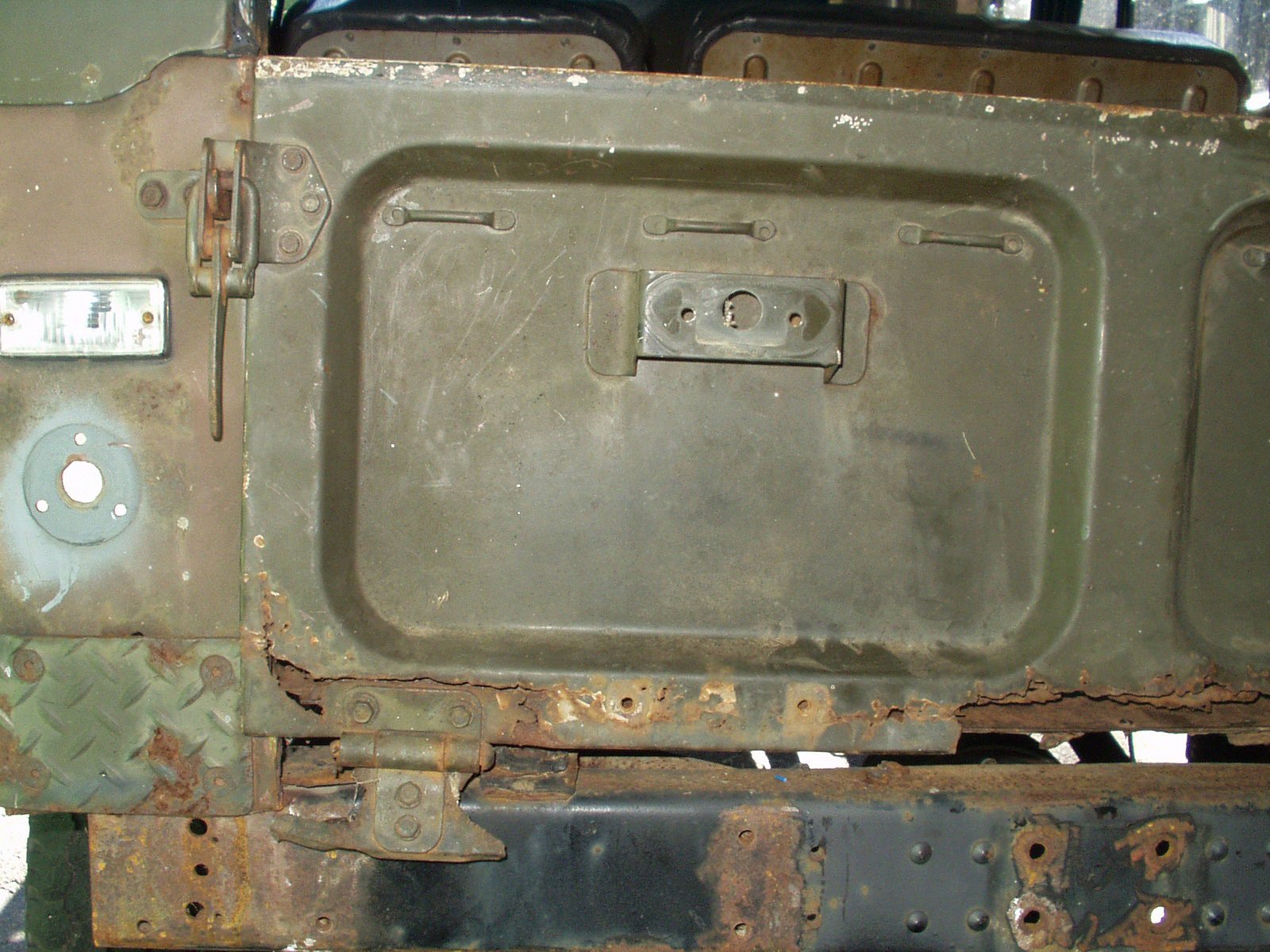
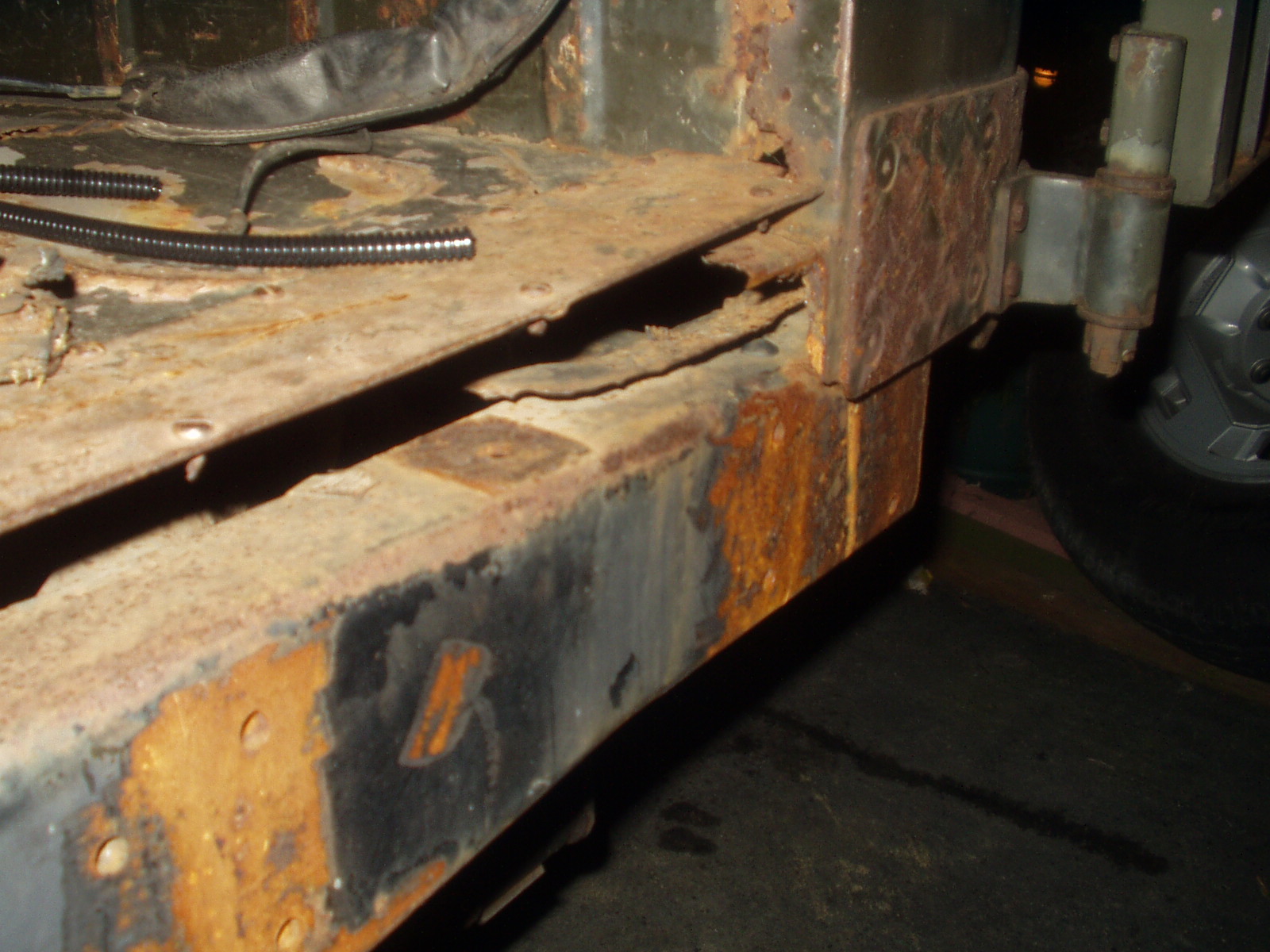
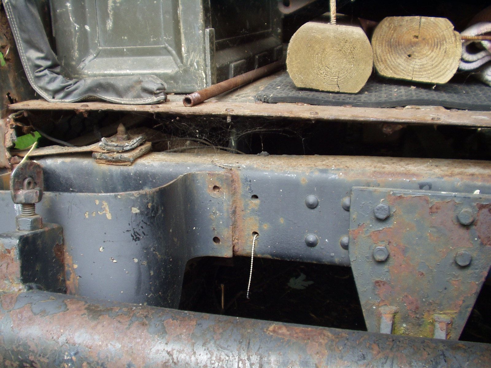
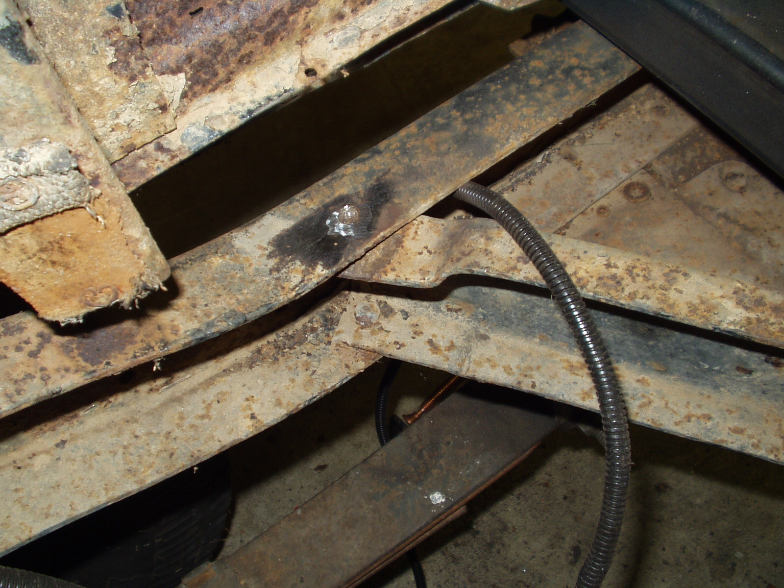
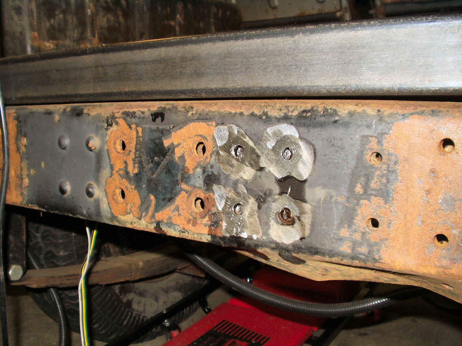
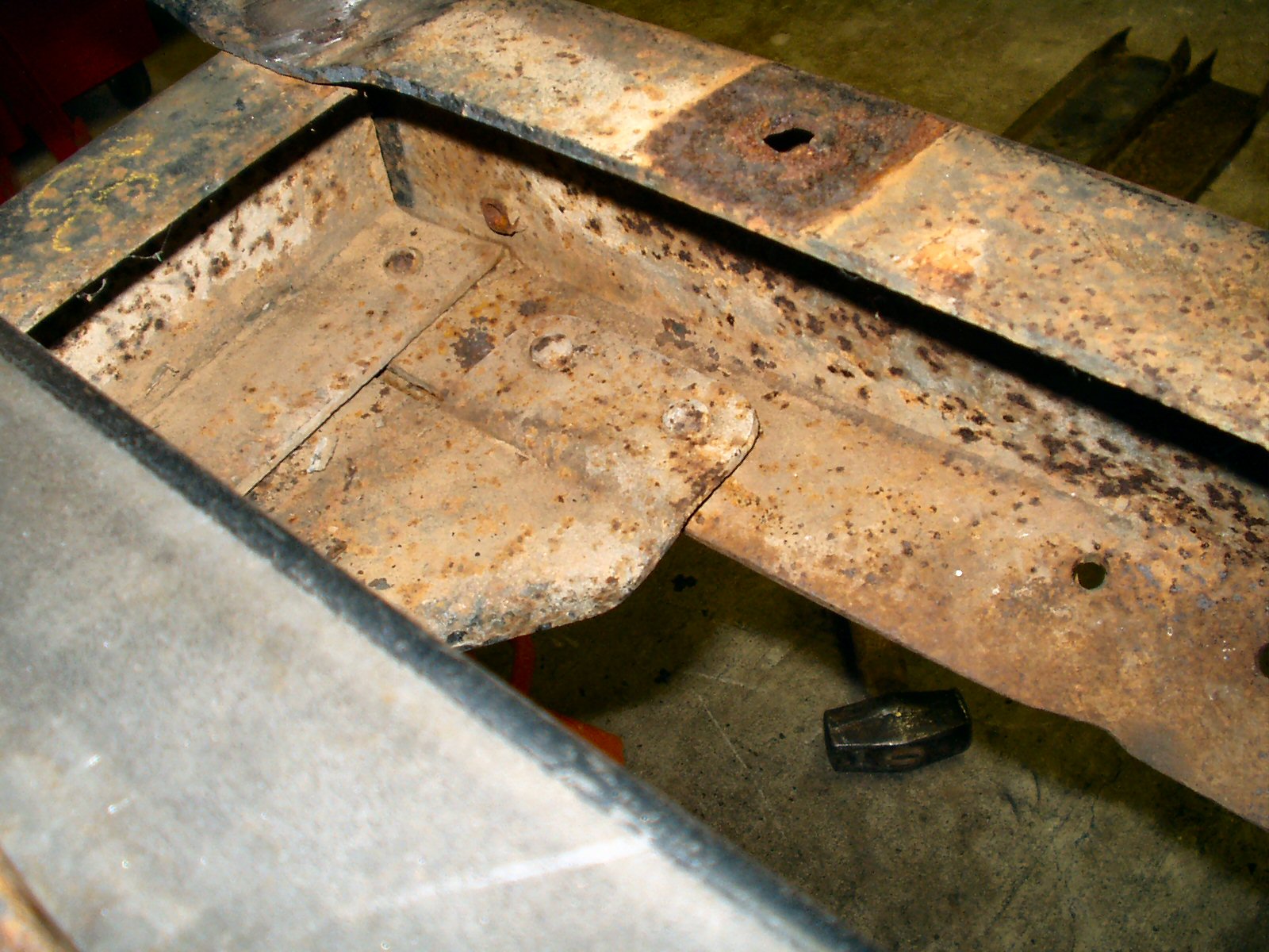
Once I got the truck running and had fixed most of the electrical gremlins I took a long hard look at what was left of the body. Not a lot there to work with! See Fig. 1-3.
Fig. 1 |
Fig. 2 |
Fig. 3 |
I researched and determined that given enough time, just a little money and the desire to learn some new skills, it would be possible to fabricate my own body panels. Every one said to start with the rear sill area. Fix this first then move on. Ok ...
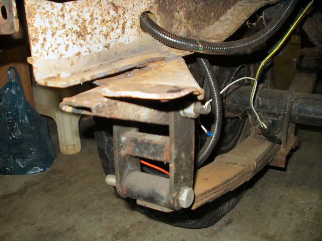
I started by removing the patch panel a PO had put in to tie the rotten floor to the 'sill' then cut out what was left of the old sill. Next up I removed what remained of the body mounts from the rear sill area. I had to use a hacksaw to remove them as I don't have a torch. See Fig. 4.
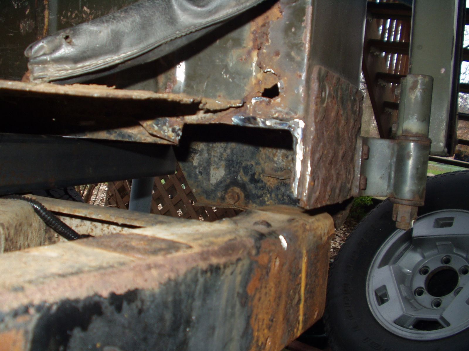
Fig. 4
The curved side parts of the rear sill that supports the quarter panels was collapsed and rusted badly so I removed them from both sides ... See Fig. 5.
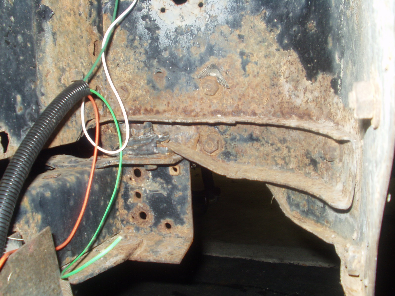
Fig. 5
I will use the best one (See Fig. 6) as a template to make a new one. See next section.
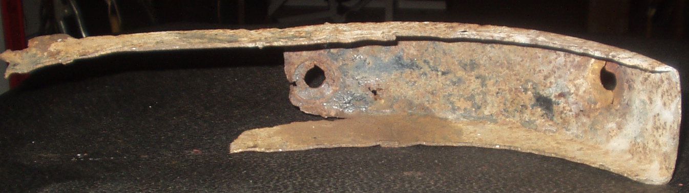
Fig. 6
Once I had the old sill parts and body mounts removed I looked closely at the rear frame cross member and its support braces. What I saw was not encouraging ...
Fig. 7 |
Fig. 8 |
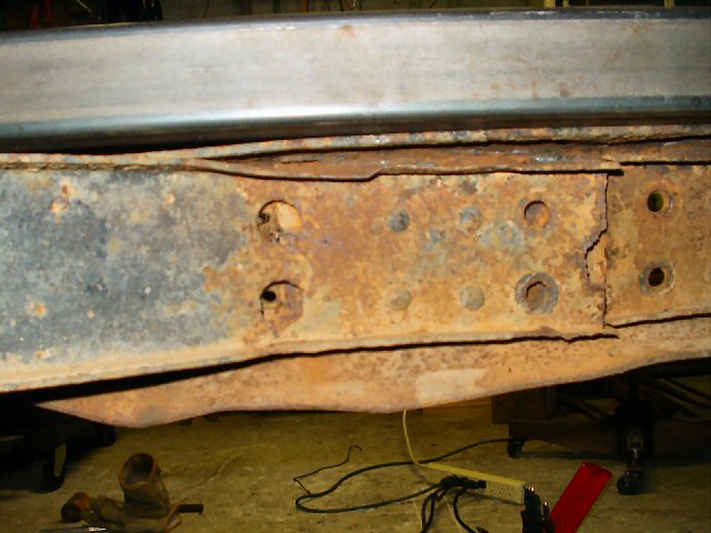
Man! Rusted and thin support braces and a severely bent rear cross member from an extraction with a wrecker and an extraction of a forklift from soft ground. ( My brother, not me!) I decided to remove these pieces and repair them. See Fig. 7-8.
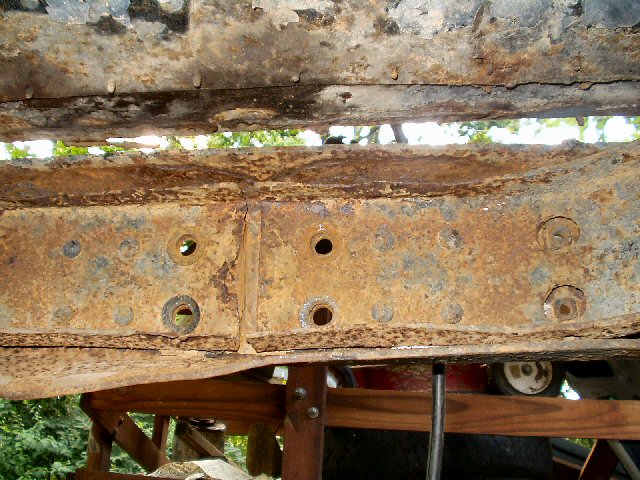
Did you know that there are 24 stubborn, almost impossible to remove rivets, that must be ground down, pounded out or cut off on a Cruiser? Also two welds which must be cut out where the rear spring hangers attach to the rear frame member.
Fig. 9 |
Fig. 10 |
Fig. 11 |
Fig. 12 |
Removing the rivets was a long, dirty, and very noisy job! This was when the wife became a bit irritated with all the beating, banging and grinding that went on for several evenings! See Fig. 9-12. I would HIGHLY recommend getting an air chisel and a rivet cut-off bit for it. I got one after I had done all this and it will cut a rivet off in about 5 seconds compared to 10 minutes of drilling, grinding, and pounding with a BFH!
Here is what you end up with.
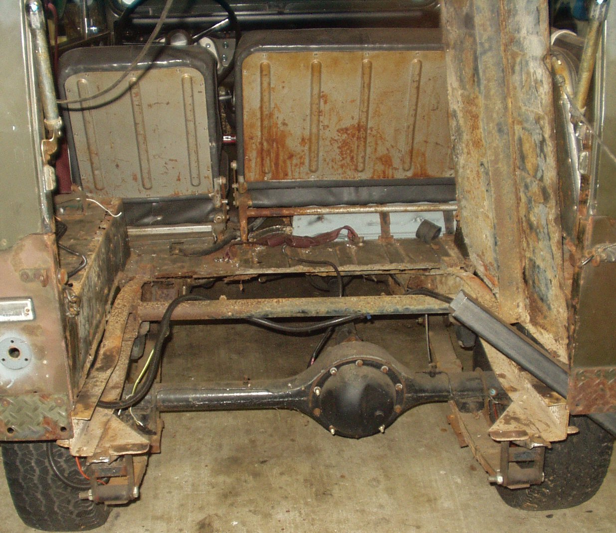
Fig. 12
I started searching around for replacement parts but after seeing what new ones cost and due to budget considerations I decided to just repair the ones I had. I started with the cross member support braces.
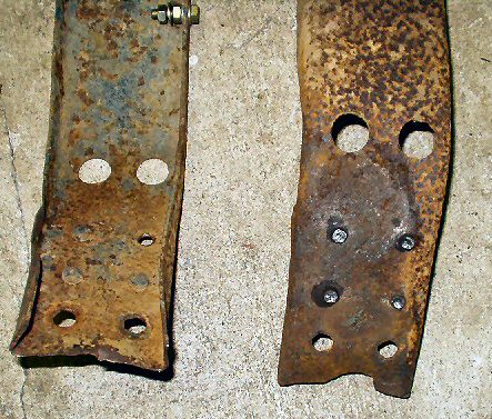
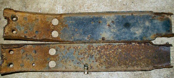
Fig. 13-14
Pretty far gone! (See Fig. 13,14) Time to fire up the welder and the hydraulic press. I first used the press to straighten out the pieces. Then I used a wire wheel and grinder to get down to what metal was left. Next I welded in metal plates to strengthen the weak areas. See Fig. 15.
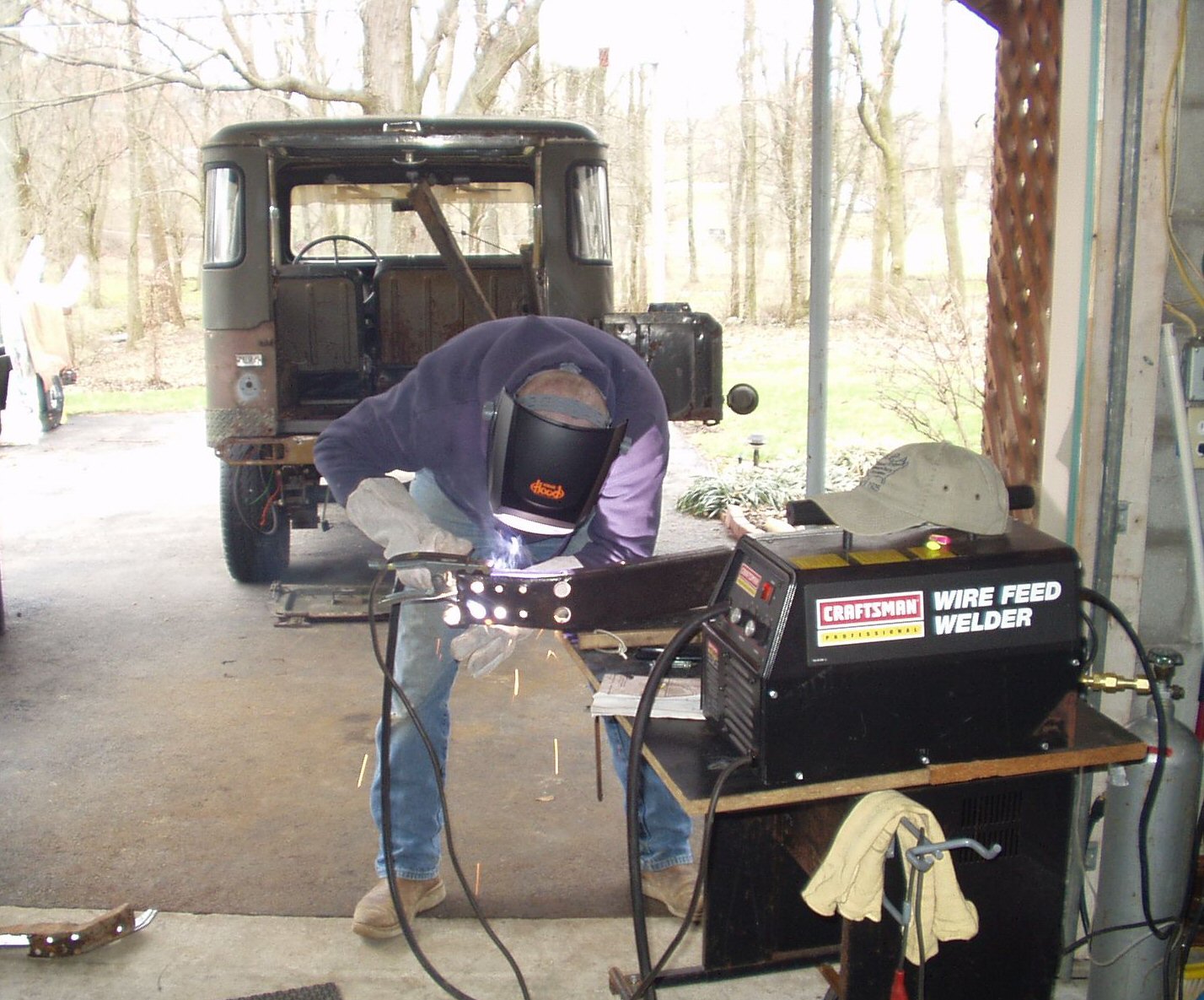
Fig. 15
Now I needed to repair the stock rear main cross member. This turned out to be impossible. The channel was just too warped and thin in the middle where the hitch would attach to be repaired. See Fig. 16. I did try to straighten the upper and lower edges on the hydraulic press but the 30 ton press would not do it! That is one strong piece of metal!
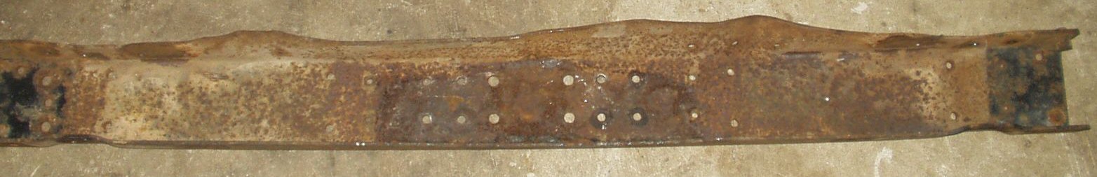
Fig. 16
So after a few emails I located a rear channel in Virginia. See Fig. 17. Since my dad lives there it was easy to arrange a trip! I picked up a set of leaf springs, a spare old style rim and a rusted blob of metal that was supposed to be the rear frame section from a 1974 FJ40. Since it uses the new style lights I also tracked down a used set of lights from Tim Jones of Odessa Tx. I will have to do a little wiring modifications to make those work ...
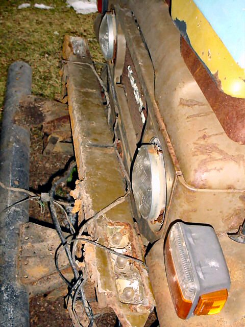
Fig. 17
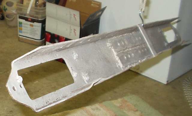
I spent a couple of hours with a grinding wheel and a wire brush and got it to look like the pic in Fig. 18.
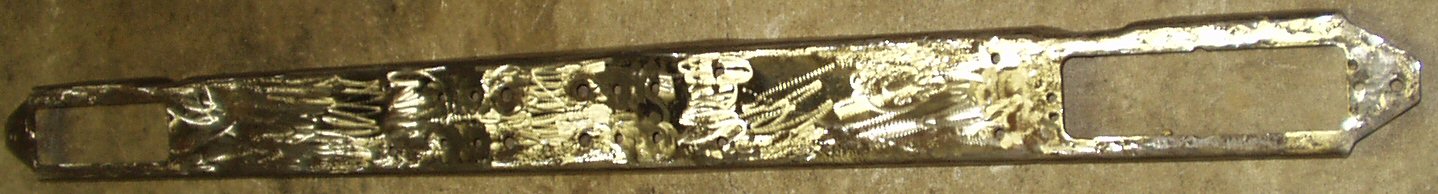
Fig. 18
It was pretty pitted with rust and was a bit thin in the center but compared to my old one it was more solid and mostly straight. I used the grinding wheel to grind off all the welded on nuts from the back. Then I used the hydraulic press to square it up a bit. Next the sand blaster was used to remove the rust from the inside so I could weld new nuts on the back side for the lights and bumperetts. (This was before I learned about de-rusting using electricity! See Fig. 19.
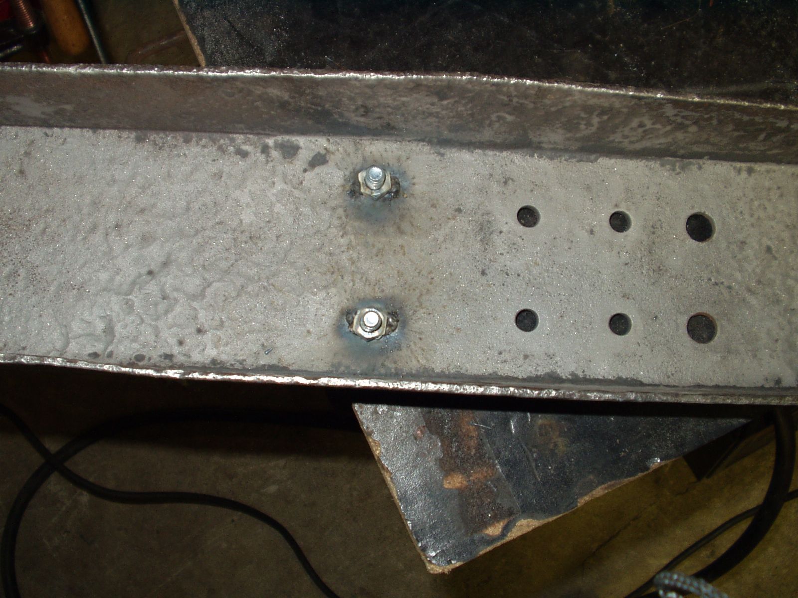
Fig. 19
I was not able to get the metric bolts I wanted in grade 8 so I got 3/8" ones instead. I drilled out all the rivet holes to match . Fig. 20 is the 'new' channel mounted. This was much harder than it looked! 24 bolt holes holding together 5 separate pieces of steel DO NOT want to line up perfectly on a 33 year old vehicle! I had to use two pin punches, a ratchet strap, several clamps and finally the drill to make it all line up.
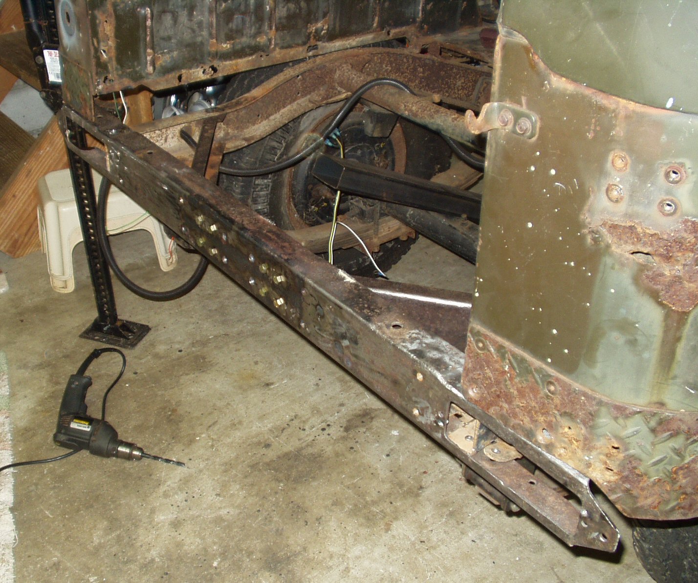
Fig. 20
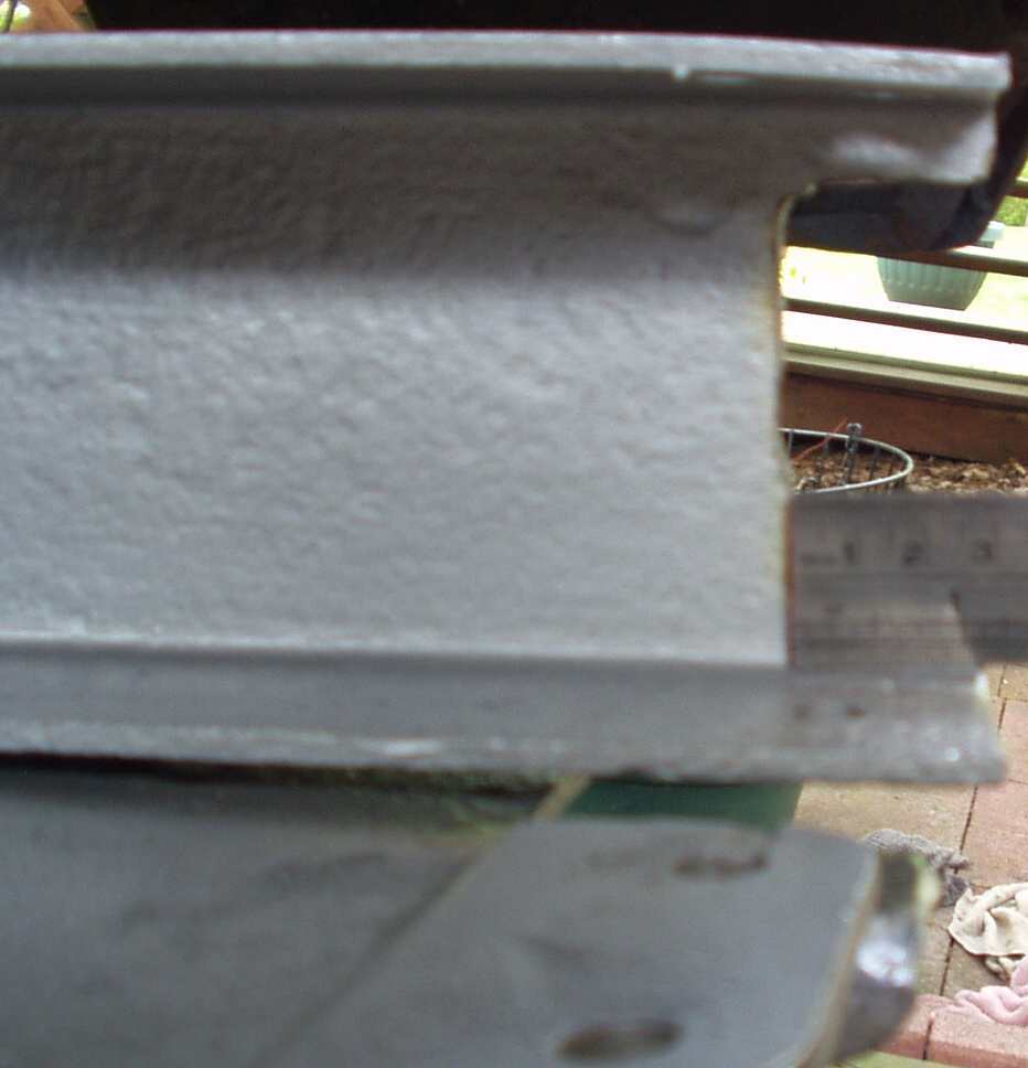
Now, since I knew it would fit I took it all back off to finish sand blasting the parts, paint them with Rust Bullet (See Fig. 21), and to cut the rear frame channels to fit the new style lights (See Fig. 22). Next up is the fabrication and installation of the new sill.
Fig. 21 |
Fig. 22 |
Next up: Rear Sill Replacement