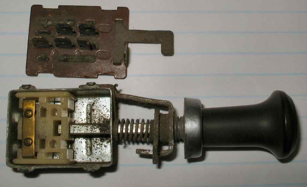
Fig. 1
Switch/Connector
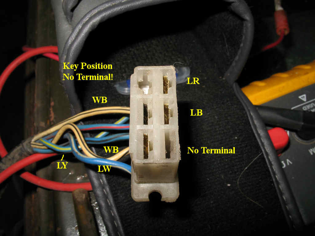
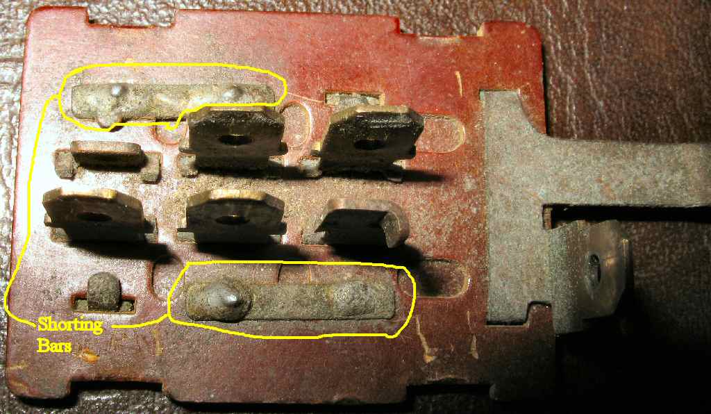
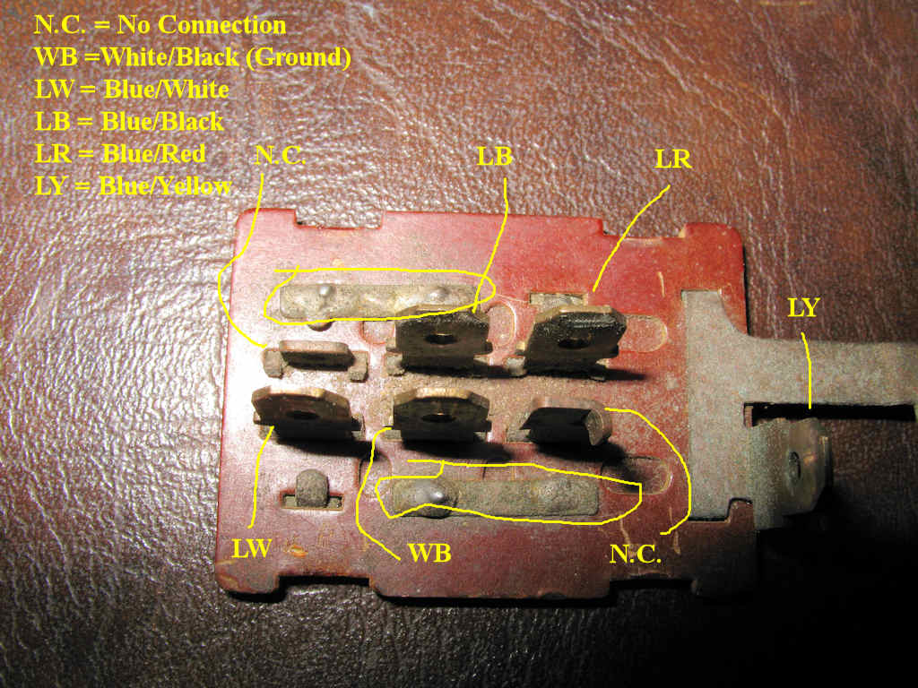
Fig. 2
Connector Key
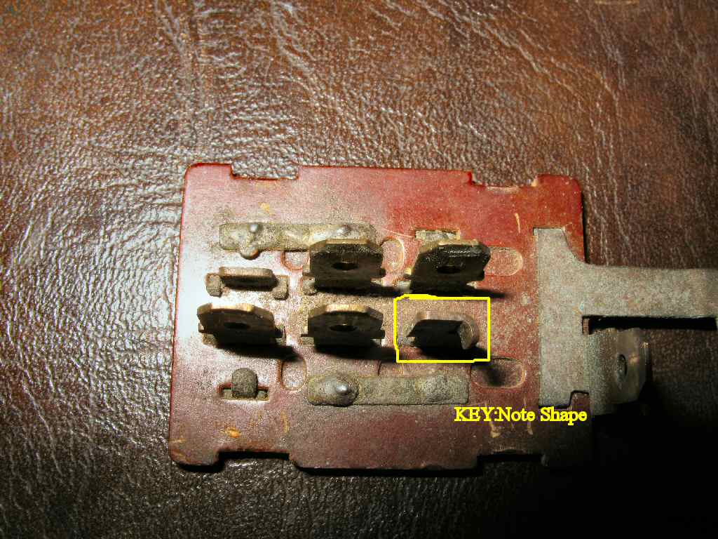
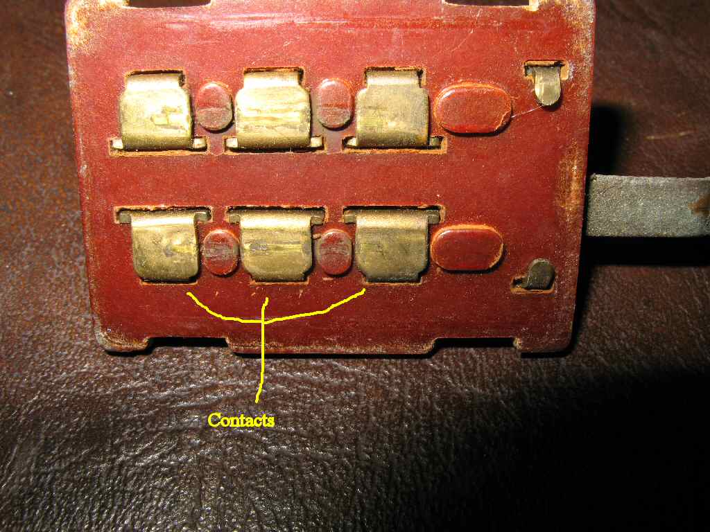
Fig. 3
Switch Key
Code |
Wire Colors |
WB |
White/Black |
LW |
Blue/White |
LB |
Blue/Black |
LR |
Blue/Red |
LY |
Blue/Yellow |
RG |
* Red/Green |
N.C. |
No Connection |
B |
Black (Motor) |
Y |
Yellow (Motor) |
Color Codes for Wiper Wiring (* just part of windshield harness)
Fig. 1 Switch/Connector |
Fig. 2 Connector Key |
Fig. 3 Switch Key |
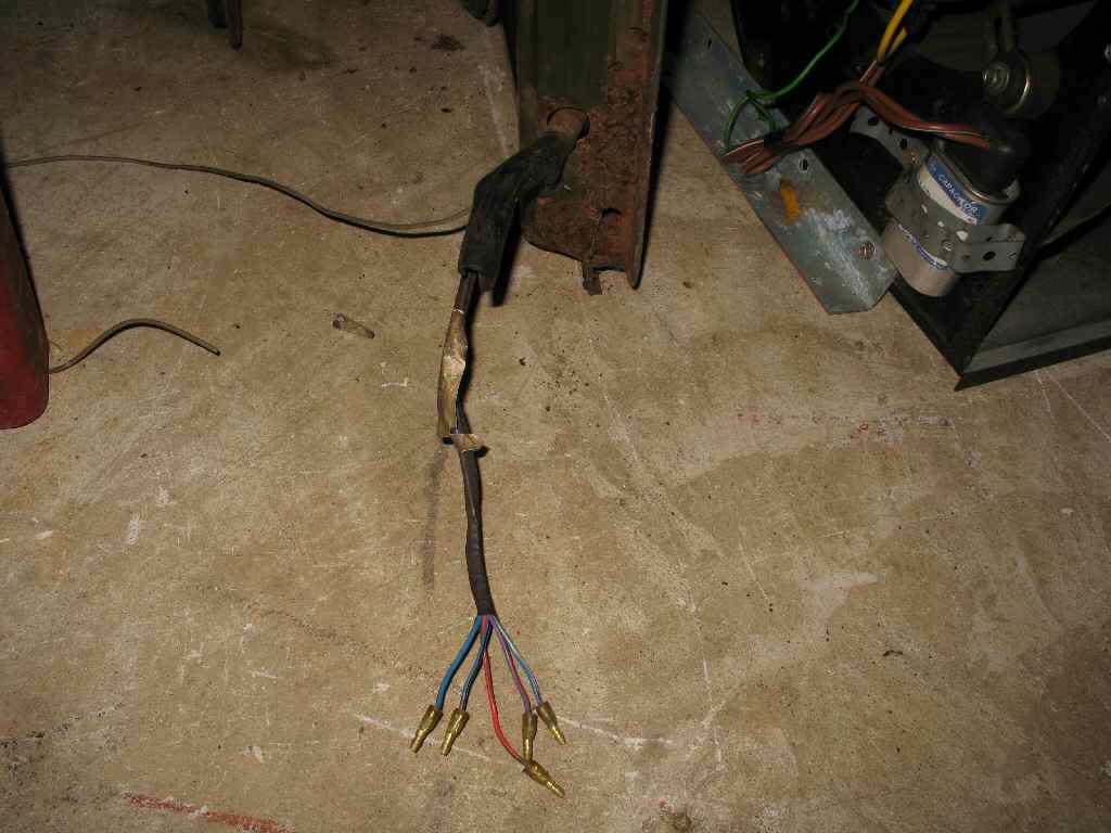
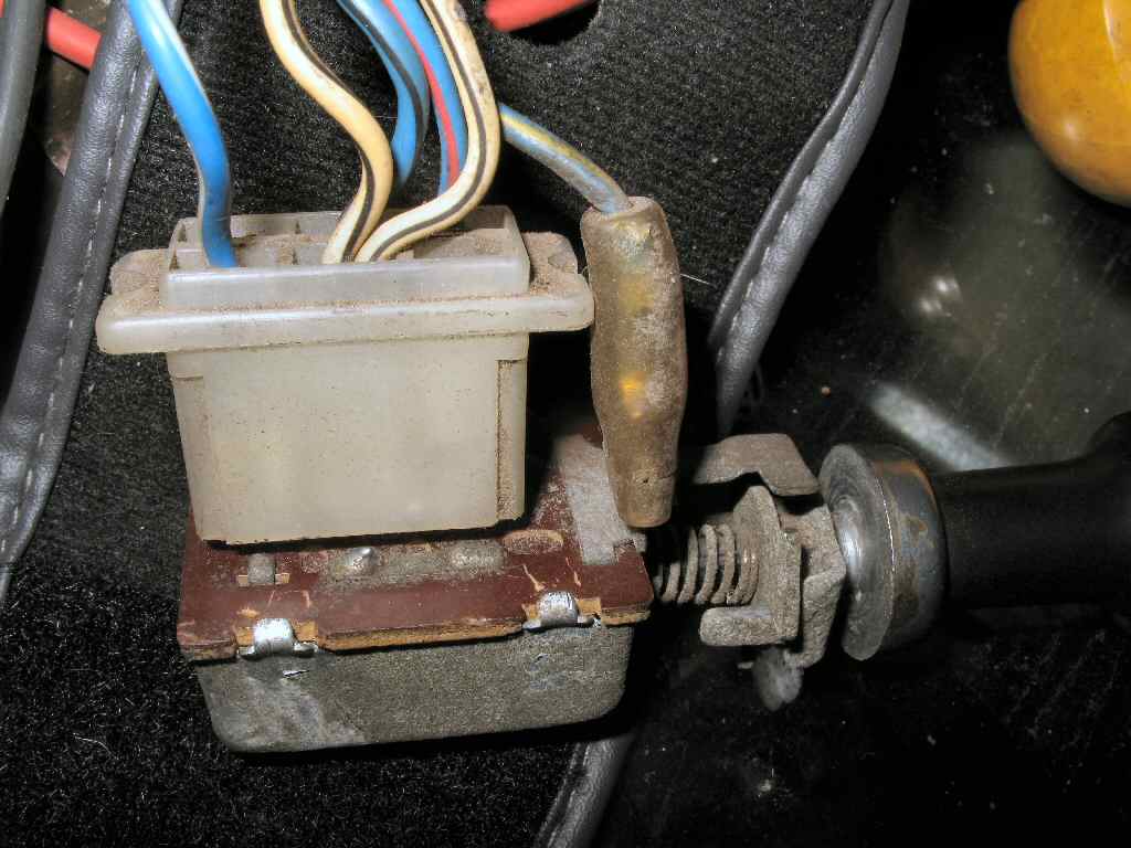
This section deals ONLY with the wiring. Later, when I am restoring the wiper assembly, I'll get into the mechanics of the wiper assembly.
Lets start with how the wiring harness is laid out. The wiring starts at the wiper/washer switch. See Fig. 1. The harness connector is a 6 terminal female connector, but only 4 terminals are used. This connector IS keyed so supposedly you cannot plug it in backwards, but rest assured, you CAN plug this in backwards! See Fig. 2 for a pic of how the key opening is a slightly different shape from the others. See Fig. 3 for a pic of how the keyed terminal is shaped differently from the other terminals. Just so you know There is NOT a +12V feed into this switch! +12V is fed into the harness (directly from the fuse panel) where it joins the harness coming from the windshield.
Fig. 4 |
Fig. 5 |
Fig. 6 |
Fig. 7 |
** Fig. 7A |
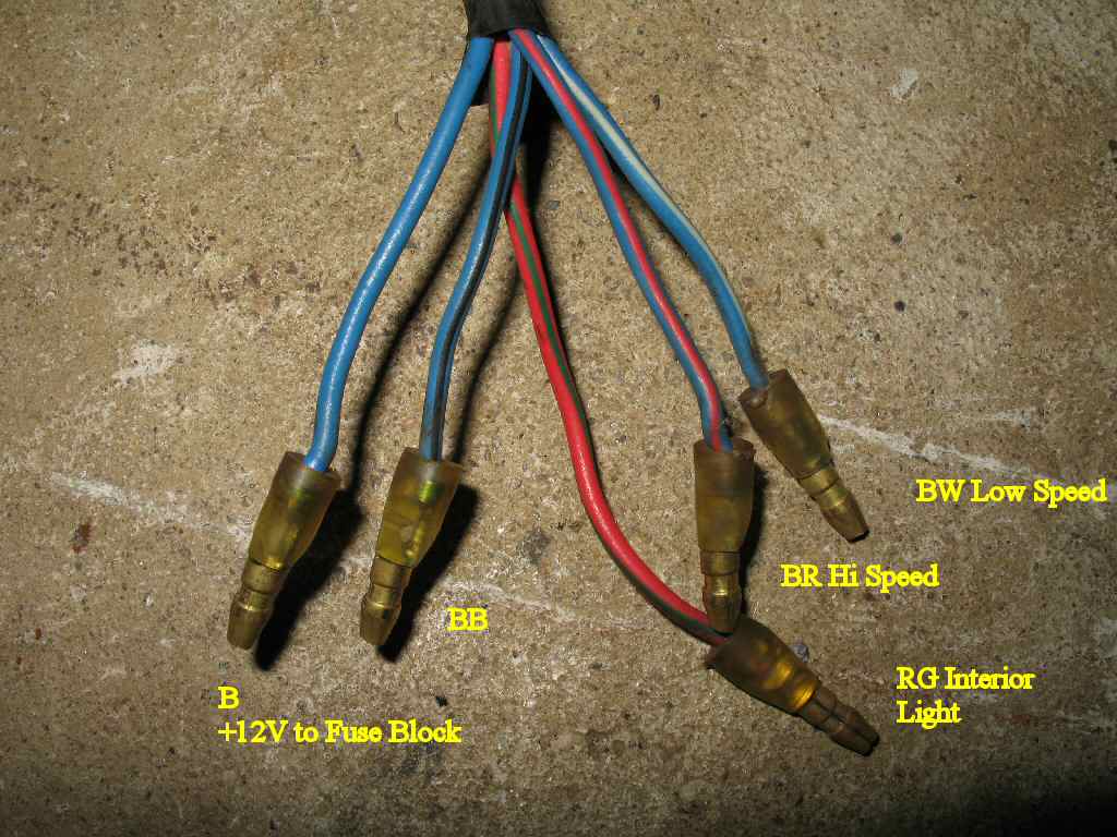
The LB,LR and BW wires from the wiper switch (see color code chart above and below) go through the harness to a set of female bullet connectors under the left side of the dash. See Fig. 4. (The double WB wires from the switch go to the main harness ground). The three blue wires are joined by two other wires.
One: A double blue wire terminated with a female bullet connector. One of these blue wires goes to the wiper fuse in the fuse panel providing the wiper motor with +12V. The other goes to the wiper washer motor providing it with +12V.
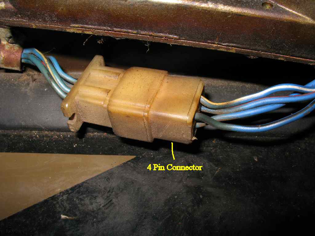
Two: A RG (red with green stripe) wire. This the interior dome light wire. All 5 wires then plug into male bullet connectors from the harness coming out of the lower left windshield. See Fig. 5-6 .This 5 wire harness goes up through the inner left windshield frame to the corner where they emerge and the RG wire separates and an extension wire plugs into the female bullet connector and continues along the edge of the hardtop to the dome light. The remaining 4 wires go across the top of the windshield to a 4 position female connector. See Fig. 7 . Then from the male 4 connector to the motor where the L, LR and LW go through a grommet inside the motor then to a circuit board that holds the brushes. A separate B wire exits back through the grommet and joins the LB wire from the switch. These go to the Park Switch.
Fig. 8 Switch Assembly |
Fig. 9 Solder Jumpers |
** Switch Wiring |
Bottom Contacts |
Switch Mechanism |
Refer to Fig. 8 . Layout a shop towel or something on your work bench. This will catch any small parts that try to roll away when you open the switch. On the top of the switch you will see 4 small metal tabs that secure the top circuit board. Use a small screwdriver, small needle nose pliers or whatever tools you have, to carefully bend these tabs up and back just enough to get the circuit board clear of the tabs. Try not to let the guts fall out when you do this! Lift the top circuit board off and examine it.
The top circuit board is all one piece. Look carefully at the top of the circuit board. See Fig. 9 . You will see that there are two solder bridges that tie the WB terminal to the N.C. terminal on one side and the LB terminal to the N.C. on the other side. On the bottom of the circuit board there are no jumpers. See Fig. 10 .
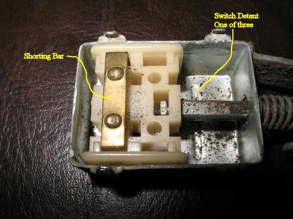
The actual moving part of the switch is shown in Fig. 11. It is very simple and consists of nothing more than a single shorting bar, and a plastic holder for the shorting bar. This plastic piece also has a ball bearing captured underneath it. This bearing falls into the three dimples in the bottom of the housing providing the stop detents for off, low and high speeds.
Code |
Wire Colors |
WB |
White/Black |
LW |
Blue/White |
LB |
Blue/Black |
LR |
Blue/Red |
LY |
Blue/Yellow |
RG |
* Red/Green |
N.C. |
No Connection |
B |
Black (Motor) |
Y |
Yellow (Motor) |
Fig. 12
Color Codes for Wiper Wiring (* just part of windshield harness)
In the OFF position: LW is tied to LB through the solder jumper.
In the LO position: WB is tied to LB.
In the HI position: WB is tied to LR through the solder jumper.
While you have the switch apart, clean all the contacts on the top circuit board and the jumper bar, and put a small dab of grease in the bottom for the detent ball. Reassemble the switch and bend the tabs back down. There should be NO play in the circuit board!
OK, So we have the switch figured out, and we know where the wires go, lets look at the motor.
Fig. 13 Brush Holder |
Fig. 14 Jumper |
Start by removing the two screws on the rear of the motor. They are 8mm. Remove the cover and set it aside. Note that the rotor may come out with the cover. That's OK, it's not too hard to get back in and you need to clean every thing anyway.
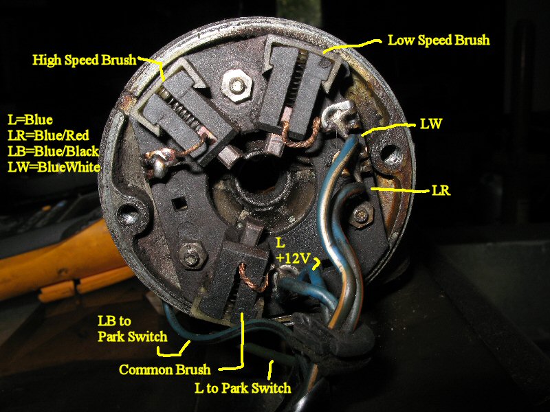
Referring to Fig. 13 you will see three brush holders. Just so you know how the LR wire gets to the Hi Speed brush, Fig. 14 shows the yellow jumper wire on the back of the brush holder circuit board.
OK, that covers the internals of the motor. Lets go on to the last piece of the puzzle...
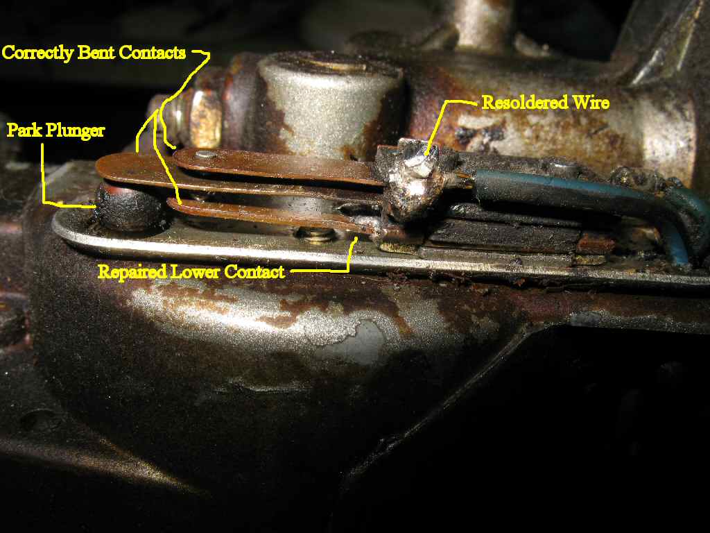
Fig. 15 FUBARED! |
Fig. 16 Repaired |
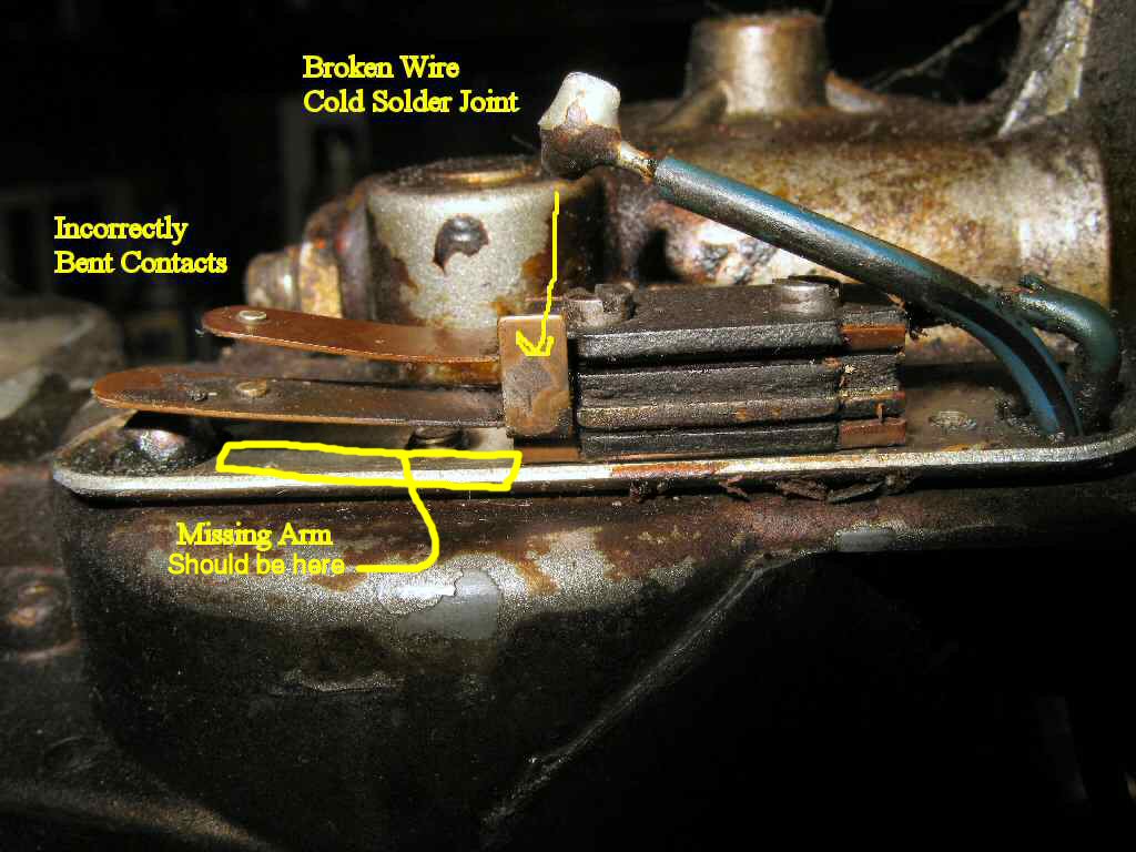
The park switch is located on the front of the motor housing. It is a simple three contact switch consisting of three thin copper arms separated by a series of insulated spacers. Two of the arms are fixed (the top and bottom arms) while the center arm is movable by the park plunger. This plunger rides on the main drive gear. There is a ramp on the gear that causes the plunger to rise up once per revolution of the gear forcing the middle contact against the upper contact. The center arm is normally down 90% of the time. When down, it makes contact with the lower arm, effectively grounding the center contact. This is why you MUST have the windshield grounded! the Park function will NOT work if you have a bad or poor ground!
Top arm: Connected to +12V via a L wire jumpered off the Common Brush (see Motor section below)
Center arm: Connected to LB from wiper switch.
Bottom Arm: Is always Grounded
My park switch was FUBARED! The lower arm was broken off, (Believe it or not I found the broken piece down inside the defrost vent!) the other arms were bent all to hell, and the LB wire had come loose due to a cold solder joint. See Fig. 15. I was actually able to solder the broken arm back on after using a Dremel tool with a wire brush to clean up both pieces. I don't know how well the electrical type solder will hold up, I may have to use silver solder to fix it later. I reconnected the broken wire and bent the arms until the Park function worked like it should. See Fig. 16.
Finally! We now have all the basic info needed to understand how the wipers work.
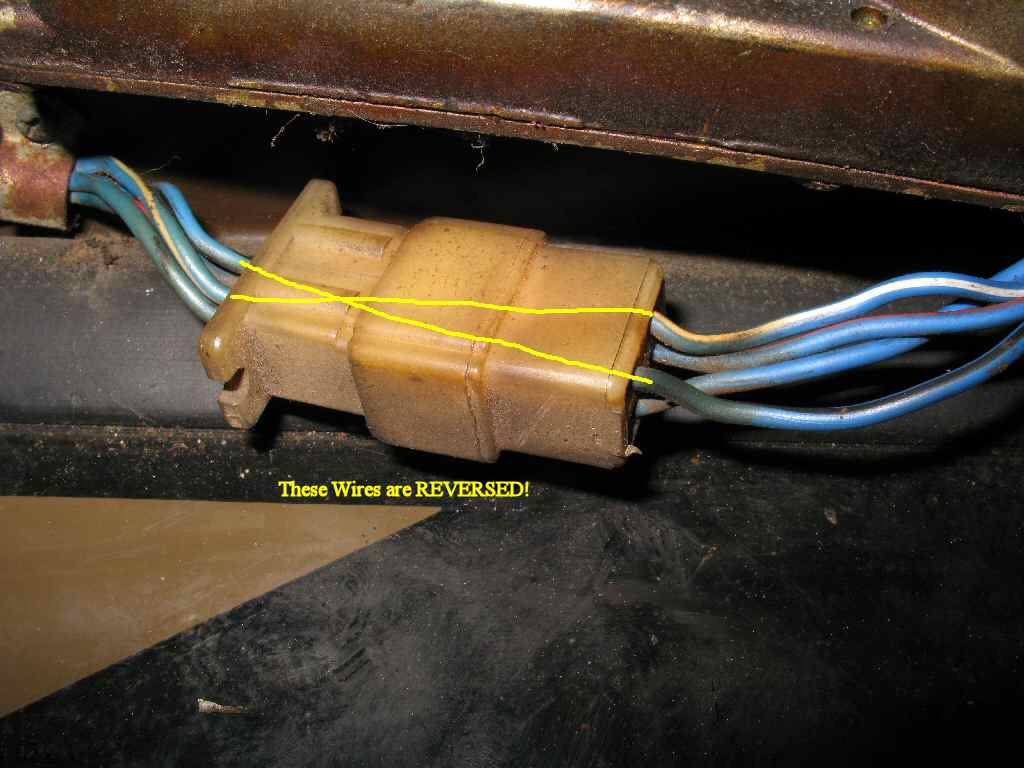
While looking at the schematic and actual wiring, I became confused with the low speed wiring. I drew out the wiper switch, park switch, and motor connections on paper. I understood the Park function wiring and the high speed function wiring, but the low speed made no sense! If you go strictly by the wiring colors, and their positions on the wiper switch, park switch, and motor, the low speed would not work! Of course it does so what was up? Long story short, for whatever reason the connector on the windshield between the harness and the motor has the LB and the LW wires reversed in the connector! See Fig 7A above. Once I took that into account, everything fell in to place. On the drawings that follow I have drawn them as they actually are to keep it OEM... So don't email about the 'crossed' wires!
The following pics show what wires are involved to make the wipers work for EACH position of the wiper switch. I'll add the washer circuit later.
The red lines indicate where current is flowing so you can trace through the schematic easily. The wiper switch in each drawing has a gray box around the contacts that are active for that switch position. Finally the position of the Park switch is shown for each condition. Remember that the park switch is DOWN 90% of the time and is completely out of the circuit for the low and high switch positions.
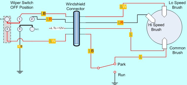
Fig. 17
Wiper Switch: Jumpers the LB and the LW wires
Park Switch: In the up or Parked position. In this switch position +12V is applied through the Park Switch to the Low speed brush and through the L wire from the fuse panel to the Common brush. Since the two brushes are at the same voltage no current can flow in the rotor and the wipers don't move.
Motor Action: Motor is OFF.
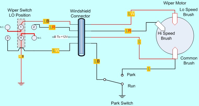
Fig. 18
Wiper Switch: Jumpers the LW and the WB wires. This grounds the low speed brush allowing the motor to run at low speed.
Park Switch: In this position the Park Switch is out of the circuit, and has no effect on the motor operation.
Motor Action: Motor runs at low speed.
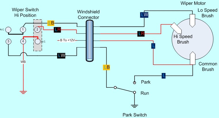
Fig. 19
Wiper Switch: Jumpers the LR and the WB wires. This grounds the high speed brush allowing the motor to run at higher speed. (It's really not THAT much faster.).
Park Switch: In this position the Park Switch is out of the circuit, and has no effect on the motor operation.
Motor Action: Motor runs at high speed.
The following information was taken from a web site pointed out to me by a fellow car nut. He owns a Ford Cortina MK1 (built in England). It explains WHY the third brush causes the wipers to go faster.
When the low speed brush is grounded, a low wipe rate of about 45 wiping cycles per minute is achieved, which increases to about 65 when the high speed brush is grounded. This rise in wipe rate is due to an increase in the current flow through the motor. When the common and high speed brushes are in use, the shorter armature path between the common and high speed brushes allows a larger current flow, which provides a higher rotational speed. As the speed is increased a rise in back e.m.f. reduces the current flow. The diagram illustrates the interconnection of the coils of a lap wound type of armature normally used for a wiper motor. High speed of operation should be avoided when there is a heavy load on the wiper blade, for example in heavy snow or on a dry windscreen.
Wiper Switch: Jumpers the LB and the LW wires.
Park Switch: Starts in the down position which grounds the LB wire. When the switch is pushed to off, the LB and LW wires are tied together. (Refer back to Fig. 17) The low speed brush is now grounded through the park switch instead of the wiper switch ground. The motor continues to run until the plunger goes to the up position. This breaks the ground connection to the low speed brush, and applies +12V to it through the upper contact on the park switch. This stops the motor very quickly so it doesn't coast past the Park position.
Motor Action: Motor runs until the Park switch is activated, then shuts off.
Well, there you have it! You are now a wiper expert!
Hosted by Global Software, Inc.
©1998 - 2023 Mark C. Baker Web Designer
Please: No part of this web site may be used without express permission... email mbaker@globalsoftware-inc.com for permission.