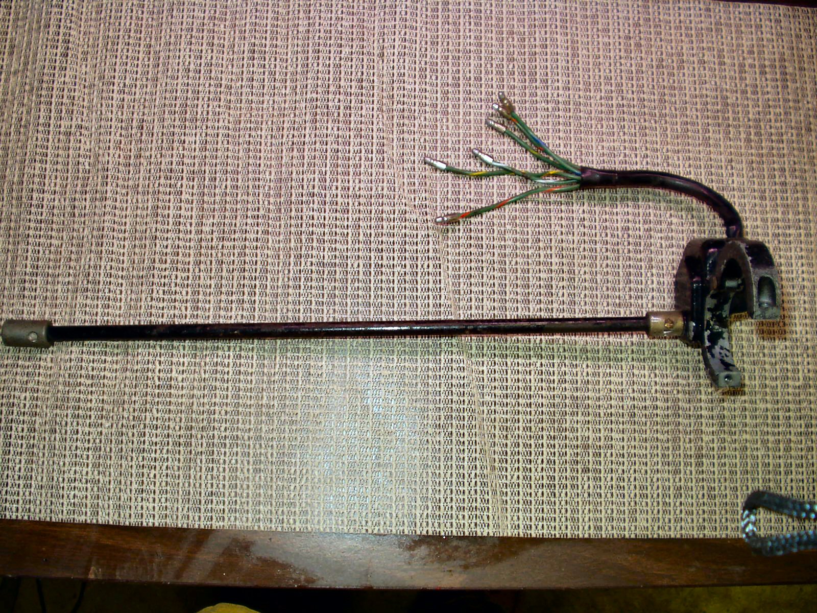
Now that I had the signals working it was time
to fix the stiff switch. I removed the unit from the truck and took it to
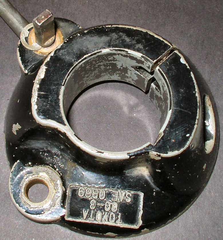
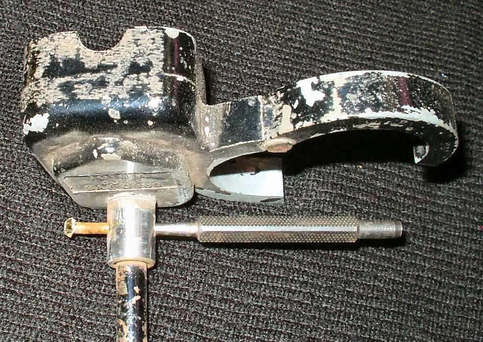
the work bench. Fig. 1 shows it before cleaning
and disassembly:
Fig. 1
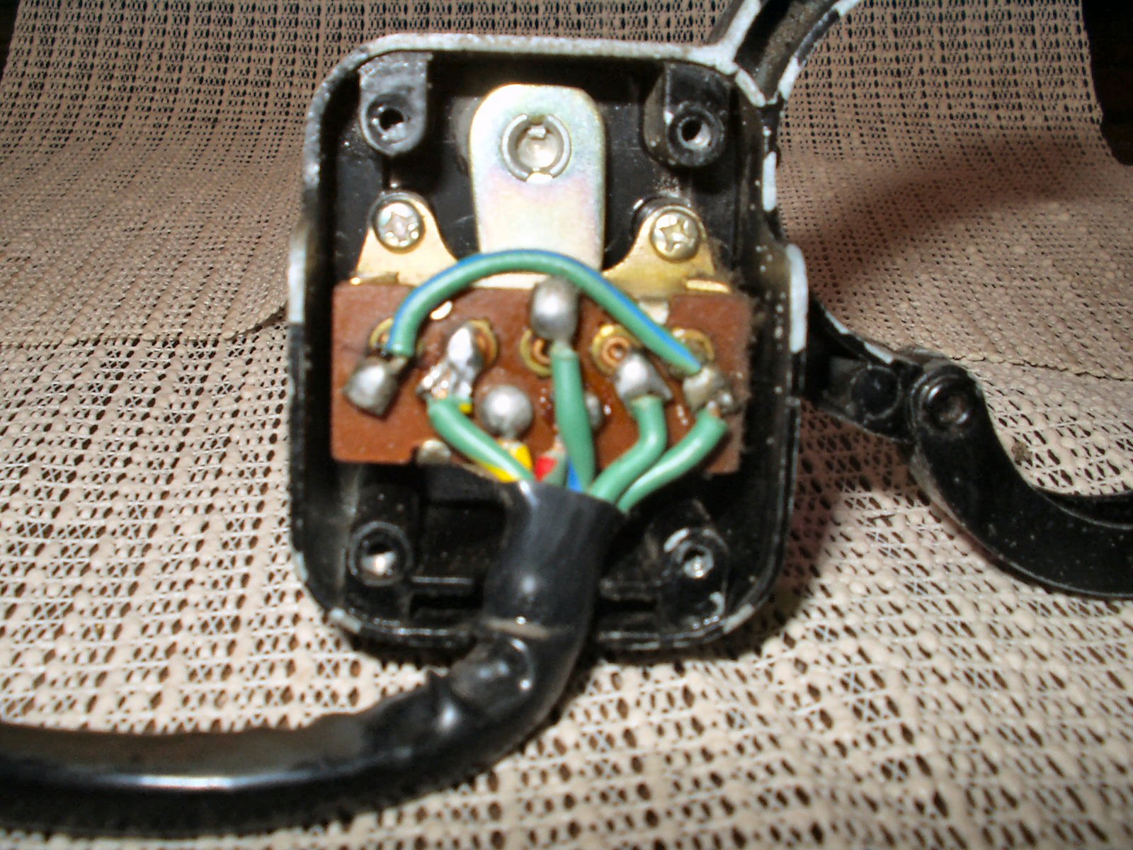
I took the 4 screws out of the back then the
three screws holding the switch in place. See Fig. 2.
Fig. 2
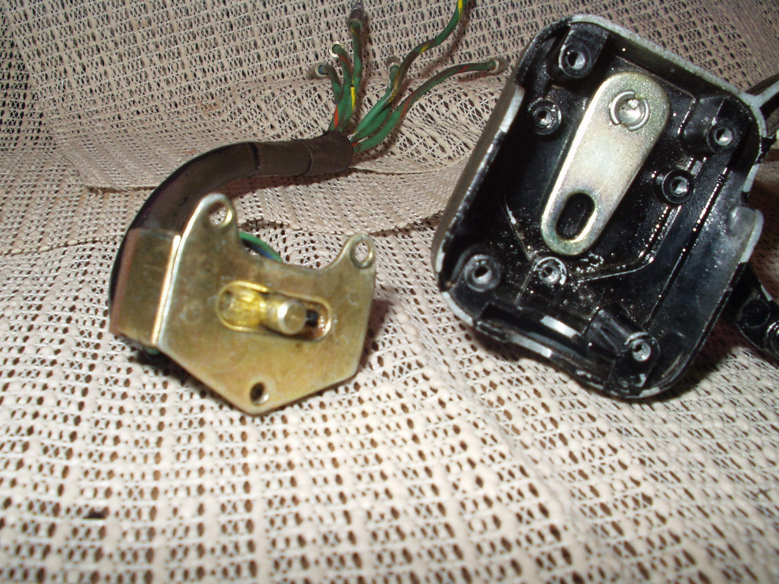
The switch itself was working fine but was a
tad stiff. I sprayed it with contact cleaner to clean out any gunk then shot
it full of dielectric grease to keep the contacts from oxidizing. See Fig.
3.
Fig. 3
(See Turn Signal Operation
for a complete description of how this circuit functions.)
The switch actuating shaft was very
stiff so I sprayed penetrating oil all around it and let it sit for a while.
I then used a pair of channel locks and tried to work it loose. Well I worked
it loose all right! I broke the pin holding the adapter end clean in two!
Turned out the pin was aluminum? The shaft was starting to loosen up so I
kept working it until it was easy to turn. I figured the aluminum housing
had oxidized around the steel shaft resulting in the tightness. I then cleaned
the housing and wires and put it all back together. I used a pop rivet to
attach the adapter back on. Sorry no pic of that mess :-)
** Updated 2-18-2005 ** With pics and text of
the upper part of the turn lever housing.
The turn signal lever can also bind in the housing
for the same reason it does in the switch housing: Oxidization!
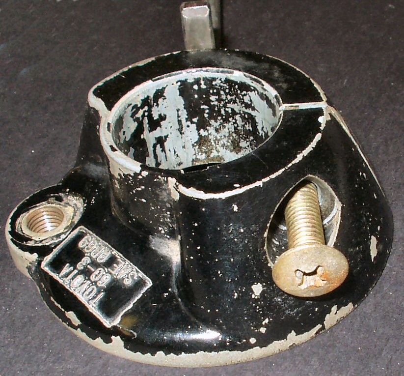
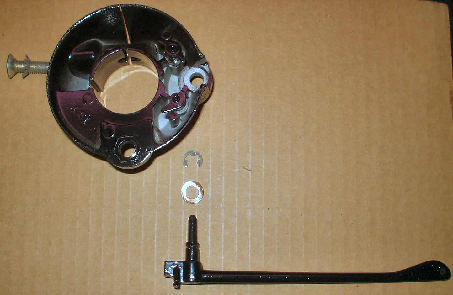
Fig. 4
shows the large phillips screw you take out to remove the lever housing
from the column.
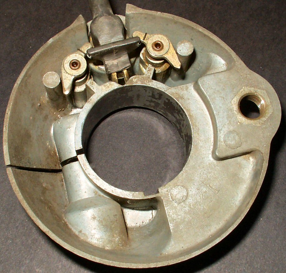
Fig. 5 shows the c-clip
and spacer washer you remove to get the lever out of the housing. Note: the
big threaded hole in the lower left corner is part of the "Three on the
Tree" shifter mechanism which I no longer have.
Fig. 6 shows the two
spring loaded stops and the spring loaded brass 'button' that rides in the
detents.
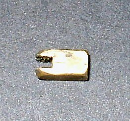
Fig. 7 shows the brass
button out of the lever.
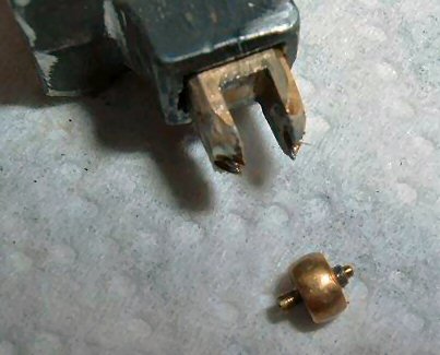
Fig. 8 shows the roller
ball that is supposed to be in the end of the button. Mine is missing, anyone
have one?
When you put it back together put just a small dab of thick
grease on the brass button sides and front. Also a light coating on the lever
stub.
** Updated 1-18-2007 ** Added several pics of turn signal switch
showing restoring it with powder coat.