Fig. 1
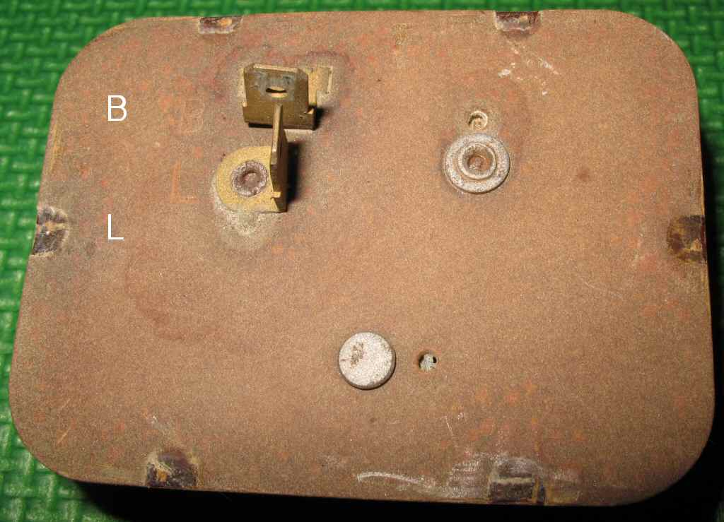
Fig. 2
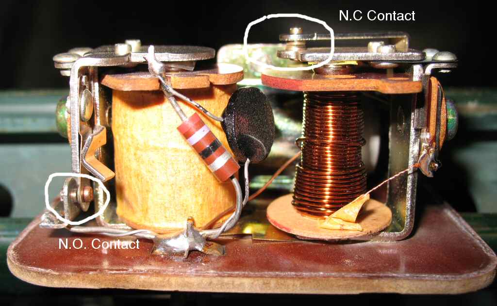
Fig. 3
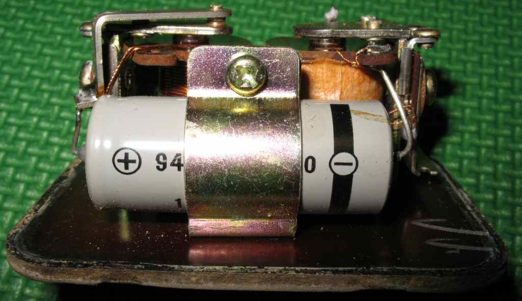
Fig. 4

Fig. 5
I receive a lot of questions concerning how the early FJ40 turn signals and Hazard circuits work. I thought, like everyone else it turns out, there was a bi-metallic flasher hooked to a couple of switches, and that was that. Well... that's not exactly how it works. Like anything electrical on the Cruiser, things are more complicated than they may at first seem.
It turns out that there are things involved in the circuit you might not suspect. For example: What do the brake light switch and Parking Brake have to do with any of this? Quite a bit. Read on...
Lets start with a basic understanding of each part, then look at them as a whole circuit. We will start with the flasher since it's common to both circuits. This is also where I got my biggest surprise.
Most folks are very familiar with the simple bi-metallic flasher unit used on most American vehicles. Apply current, light bulb lights, current heats up bimetallic element until it warps, contacts open, current flow stops, light bulb goes out, bimetallic element cools and warps the other way closing the contacts again, repeat, repeat. It's a very simple device and works very well. Toyota for whatever reason choose to not use this device. Instead they designed a complicated circuit based on two, twin coil relays, and a timing circuit that consists of a large capacitor, a resistor, and a thermistor. See Fig. 1 - 4.
Fig. 1 |
Fig. 2 |
Fig. 3 |
Fig. 4 |
Fig. 5 |
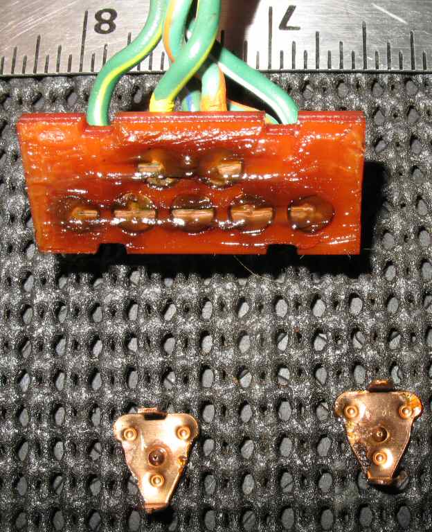
Fig. 2 shows the two connections on the bottom of the flasher. They are labeled B and L. B goes to turn signal switch B terminal (+12V) and L goes to the four turn signal/brake lights. These are what the wiring harness plugs into.
Fig. 3 shows the two dual winding coils L1 and L2 (L2 on the right), and the resistor and thermistor in parallel that charge the large capacitor (shown in Fig. 4.)
Fig. 5 shows the schematic of the circuit. I believe this to be correct but if you want to research this further and send me any changes I will post them here with proper credit.
The initial condition of the circuit: The cap is uncharged, the contacts of coil L1 are open, and the contacts of L2 are closed.
+12V is applied to terminal B either through the turn signal switch or the Hazard switch. This allows current to flow through L2 and the N.C. set of contacts of coil L2 straight to the L terminal on to the lamps and back to ground. The total resistance of that branch of the circuit is 3.6 ohms. Once the current flow reaches the pull in value of L2, L2 opens the N.C. contacts. Current now flows through L1 and R1 AND L2 and L2A. L2 and L2A keep the solenoid pulled in keeping the N.C. contacts open. Current flow through L1 closes the N.O. contacts and current can now flow through the bulbs lighting them.
In the meantime the capacitor is charging through the resistor and thermistor. Once the cap charges to a value of about 11 volts, L1 contacts close and L2 contacts open and the lights go out. The closing of L1 discharges the cap through the windings of L2. Once the cap discharges to about 3 volts L1 opens and the cycle repeats.
There are only two things that can go wrong with the flasher. The large cap can fail, or the contacts of either L1 or L2 get out of adjustment or get burned and pitted. Either one will cause the flasher to stop, well, flashing. Keep in mind that the most common point of failure is actually caused by not enough current flow through the lamps! Bad grounds are the number one failure point. ALWAYS verify the grounds for EVERY light before doing anything else to trouble shoot a turn signal/Hazard failure!
First check the points for pitting and burning. Dress them with a points file or some extremely fine sand paper. Make sure to clean the contacts after dressing to remove all particles. I could not find a point gap setting in the FSM but I measured a working flasher and got these values. L1 gap = .008 and L2 = .014. This should be close enough to get them working.
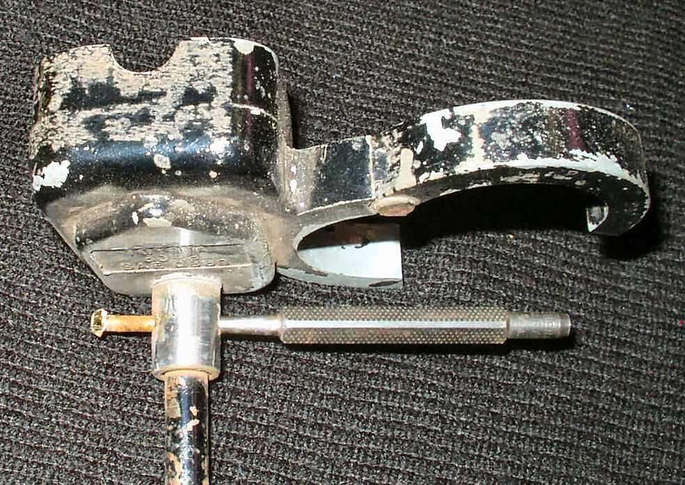
Fig. 6 Turn Switch |
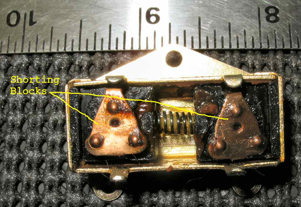
Fig. 7 Shorting Blocks |
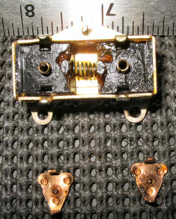
Fig. 8 Block Springs |
Fig. 9 Contact Board |
 |
Note: Pics show the switch removed from the turn signal housing. (See Turn Signal Mechanicals for a complete description of how they physically work.)
The signal switch itself is pretty simple. See Fig. 6. Effectively it's a SPDT switch. Internally though it's a bit more complicated. See Fig. 7-9.
Notice the dielectric grease? If you disassemble the switch and de-grease it, make sure you re-apply this after cleaning up the switch.
Here is a schematic of how the switch works in conjunction with the Brake switch and the Hazard switch.
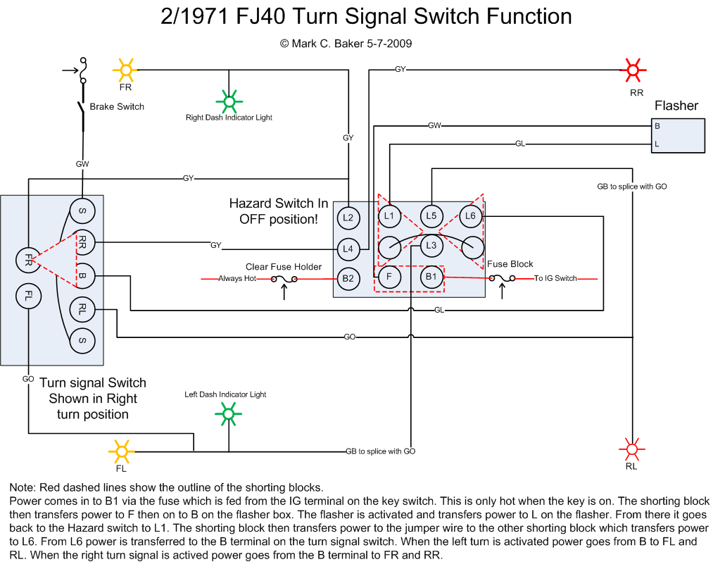
+12V power to the turn signal switch is actually fed through the Hazard switch. When the Hazard Switch is in the off poistion power is fed through a fuse block fuse that is controlled by the key switch and on to the B terminal of the turn switch. When you move the lever, to say give a left turn, the mechanical lever rotates, engages the switch pin which moves to to the left dragging the shorting block on the RIGHT to the LEFT.
Hosted by Global Software, Inc.
©1998 - 2023 Mark C. Baker Web Designer
Please: No part of this web site may be used without express permission... email mbaker@globalsoftware-inc.com for permission.