Here was the deal: Press the horn button and all I got was a
weak brrrrttttt.. I spent two hours cleaning the horn button ring, fuse contacts,
horn contacts, relay connections, horn grounds, taking the actual horns apart
and cleaning and adjusting them. Press the horn and I'm rewarded with a bit
stronger brrrrttttt... Hmmm ... Measure power at the horn harness terminal B
to relay, good solid 12.53V , measure ground resistance at terminal S on horn
relay harness when button pressed , a little high but enough to trigger relay
solidly, measure voltage at terminal H on horn relay (with relay plugged in)
and get a good 12.41V when relay is triggered...WTH? Finally I jumpered 12V
straight to the horns through the harness connector and jumped when the twin
horns cut loose. OK so I figured the relays contacts were burnt or corroded
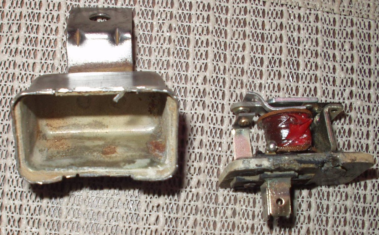
so I decided to take the relay apart. This is a sealed Toyota metal case relay
and was a bitch to get apart. I used a cut-off wheel on a Dremel tool. After
getting it apart I looked at the contacts and they looked a bit dirty so I cleaned
them with a bit of emery cloth. I figured this would do it no problem. I even
measured across the closed contacts from the inside and got .2 ohms. Put it
back in the circuit and press the horn button ... brrrrttttt.. @$@#WTF?%$#&$!
After MUCH head scratching I finally figured out that the wire connected to
the B contact for the battery had corroded INSIDE the relay housing! When I
measured across the contacts from the OUTSIDE connections I had a high reading
of 93 ohms! This gave me just enough current to the horns to get a brrrrttttt...
So I added this relay to the growing list of items I need to procure for the
Cruiser ...
** Update 10-1-2004 I bought a pair of inner fenders from Ron
Lang in Colorado Springs. On the passenger side was a GOOD horn relay! My horns
do now blow! **
** Update 2-17-2005 ** Added the following section to help others
with the disassembly of the steering column and some trouble shooting tips for
when their horns fail to blow!
Before you start trouble shooting, see Fig.
A below for a schematic with the horn circuit highlighted. Red is the
+12V path and Green is the ground path. Also see Fig.
B for the factory manual page of the horn.
Fig. A
Schematic with Horn Circuit Highlighted
Fig. B
Page from Manual
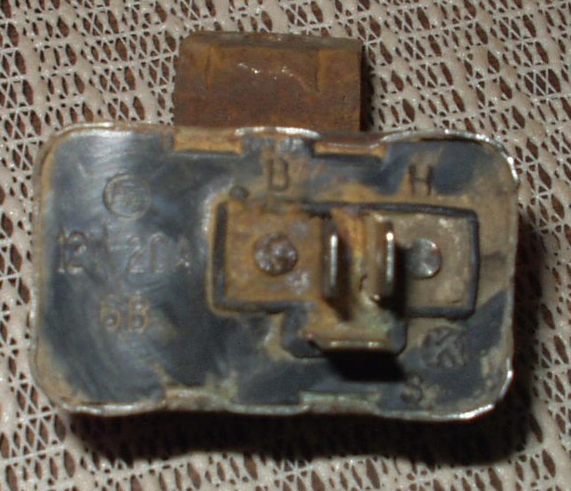
The Toyota Land Cruiser horn works backwards from what you may
be used to. Here's how it's connected: The Horn Relay B Terminal (hot side of
the relay triggering coil) is connected to +12 V through a 20 amp fuse that
is hot all the time even with the key off. The Horn Relay S terminal (ground
side of the relay triggering coil) is connected to the horn button. The Horn
Relay H terminal is connected to the horns themselves. When you press the horn
button you connect the S terminal to ground. This completes the circuit for
the relay triggering coil which then turns on and activates the relay. This
closes the relay contacts physically connecting terminal H to terminal B thereby
sending +12V to the horns.
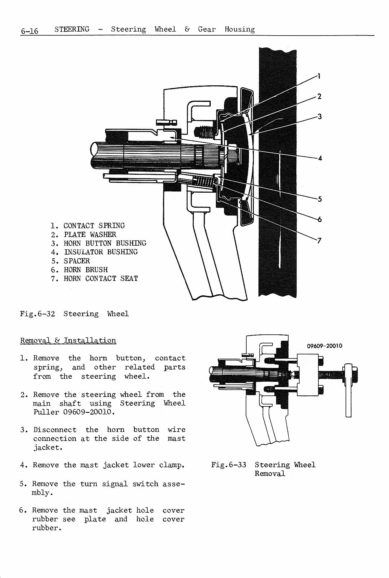
Fig. 1
Horn Button Parts
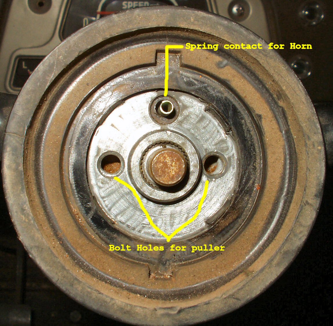
Fig. 2
Horn Button Removed
Fig. 3
Contact Spring
Fig. 4
Contact Spring and Horn Contact Seat
Removed
Fig. 4A
All the horn parts
Fig. 4B
Horn Brush Close-up
Fig. 4C
Really Close-up
Pry the Horn button off with a screwdriver. If you wish to
take the horn button itself apart then flip it over and bend the two metal
tabs holding the retainer ring in place up. You can now press the center out.
See Fig. 1 for the parts.
Remove the 14mm nut from the end of the steering shaft. See
Fig. 2.
Remove the nut and plate washer to expose the contact spring.
See Fig. 3. When reassembling clean the contact
spring of any crud or corrosion.
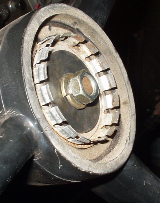
Remove the Contact Spring and Horn Contact Seat to expose
the puller bolt holes and the horn brush. Remove the brush . See Fig.
4-4C.. Clean any corrosion off the entire spring and the brush end.
If the brush end of the spring is worn down and is now too short for the spring
end to contact the bottom of the horn button contact spring then you must
either get a replacement or space it out so it will reach. You can try using
a spring from a ball point pen to extend the reach of the other spring. You
will have to cut it to fit.
Fig. 5
Removing Steering Wheel
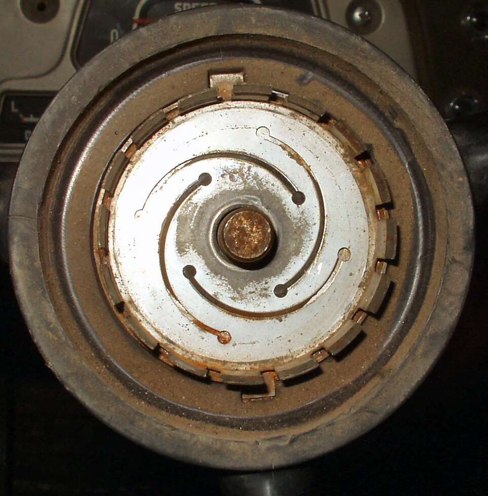
Fig. 6
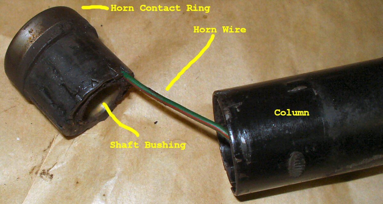
Horn Contact Ring
Fig. 7
Column End Cap Insulator Bushing
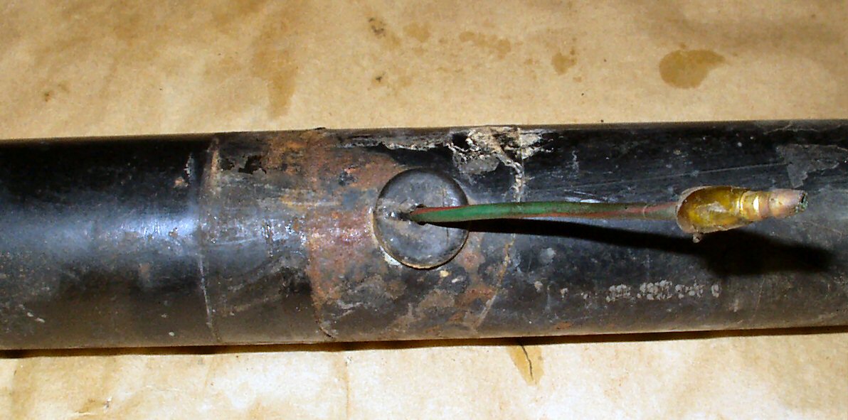
Fig. 8
Exit Hole for Horn Wire
Use a steering wheel puller to pull the steering wheel off.
See Fig. 5 This will expose the Horn Contact
Ring. Use a pencil eraser or a wire wheel on a Dremel tool and clean the entire
top surface of the ring. This is what the horn brush rides on to make ground
contact when the steering wheel turns. Now get your multi-meter out and check
for continuity from this ring to the wire end shown in Fig.
8. There should be continuity. If there is not continuity you will
need to remove the turn signal lever housing to get to the end cap.
Remove the large phillips screw on the passenger side of
the housing and by twisting back and forth and pulling up, remove the housing.
This will expose the Column End Cap and Insulator bushing shown in Fig.
7. The wire is probably broken here or down inside the column. Clip
the bullet connector off the wire shown in Fig. 8
and pull the Column End Cap with wire out the top. Pry the rubber bushing
out of the column that the wire went through and set it aside.
Slit the rubber on the end cap with a razor blade so you
can get to where the wire attaches. Remember this has to go back in so don't
mess it up too bad! Unsolder the old wire from the end cap, solder on a new
piece, feed it back down the column and out the hole.
Now thread the wire through the rubber bushing, press the
bushing back in place then crimp on a new male bullet connector. These bullet
connectors, both male and female, are available from Waytek
Wire.
Reassemble the column making SURE to remove all traces of
corrosion from the Horn Brush, Contact Ring, and Spring Plate! Test it with
the meter. Put the meter in continuity mode and attach one lead to the wire
coming out of the column and the other on a good ground. When you press the
horn button you should get continuity. You may have to slightly turn the steering
wheel to make good contact.
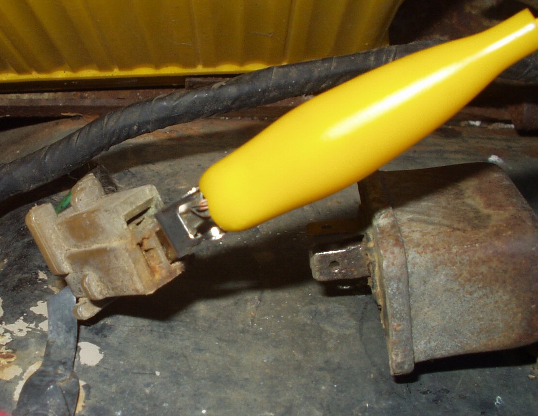
Plug that wire back up and try the horns. If the horn relay
is not clicking then unplug it, clean the contacts on it and the relay socket
and try again. If still nothing then check for +12V in the relay socket Terminal
B. See Fig. 9. If you have +12V there then get
a new relay! If you don't check the fuses and wires.
Fig. 9
Relay Socket
Fig. 10
Relay Bottom
Fig. 11
Relay apart
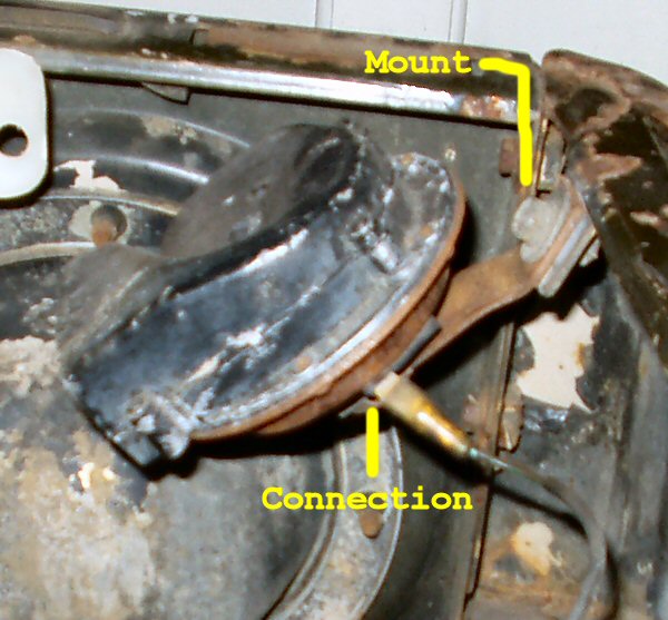
Fig. 12
Horn Mount
One last thing. The horns THEMSELVES must be
grounded! Remove the horn mount bolt and clean to bare metal under the bolt
the put it back on. See Fig. 12.
.jpg)