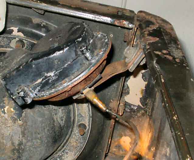
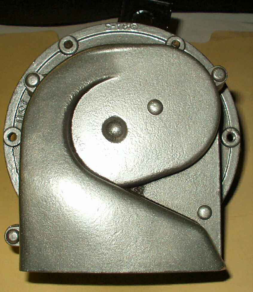
On the 1971 FJ40 there are two horns, one mounted to each apron.
There is a low tone horn and a high tone horn. The low pitched horn is on the
drivers side, the high on the passengers side. There is a raised L or H cast
into the bottom front of the top aluminum cover to tell you which is which.
See Fig. 1.
Horn Mount
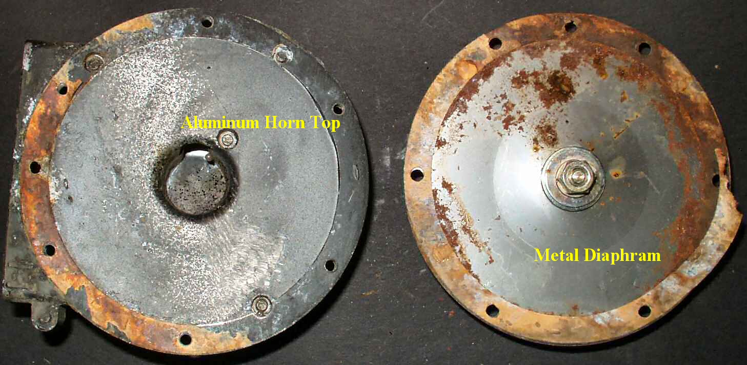
On the previous page I got the horns working electrically but
wanted to spruce them up a bit. Upon inspection I realized the bottom of the
horn was a steel shell (rusted) and the top was aluminum painted black. I started
by disassembling the horn.
Fig. 1
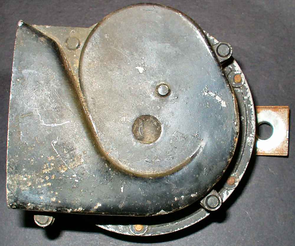
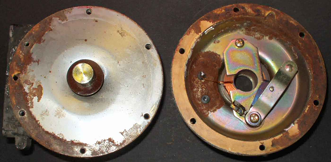
Horn Bottom
Fig. 2
Horn Top
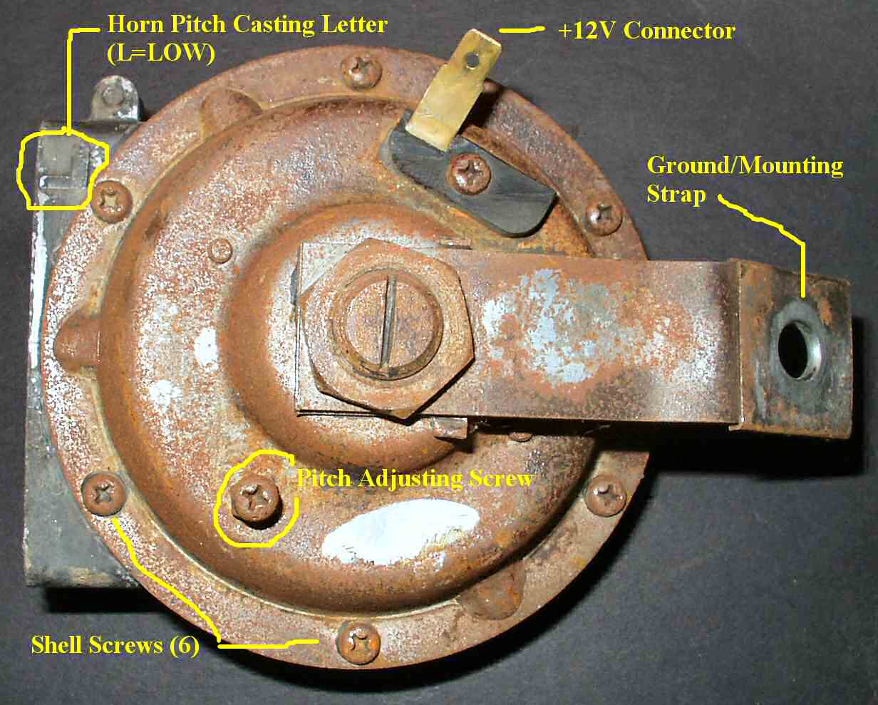
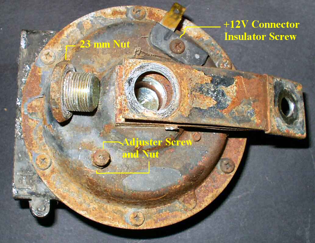
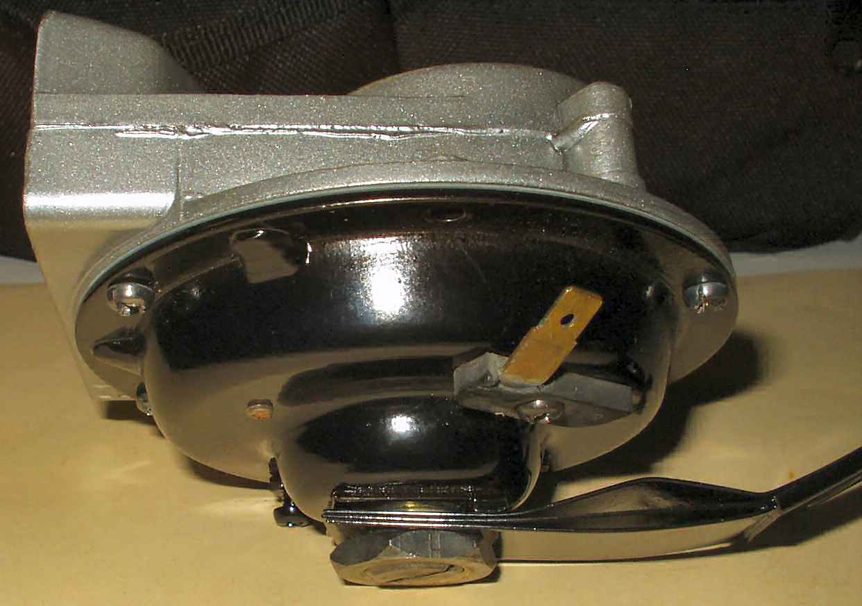
Start by removing the 23 mm nut that holds the ground strap
on. A 15/16 socket will work. The solenoid stud may turn out also. See Fig.
3. Next remove the 6 small 4mm phillips screws holding
the horn halves together. Use your JIS screwdrivers for this or plan on replacing
the screws! Separate the halves. See Fig. 4. Separate
the sound plate from the upper horn half. See Fig. 5.
You will notice there are paper gaskets between these parts. These gaskets are
not available from any source so you will have to make your own. I provided
a template below. Make sure to replace BOTH gaskets! They also act as electrical
insulators for the diaphram!
Fig. 3
Remove Ground Strap
Fig. 4
Remove Screws to separate halves
Fig. 5
Remove metal diaphram from top
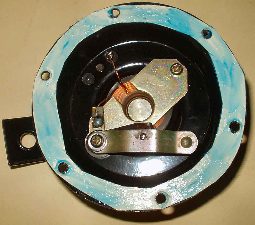
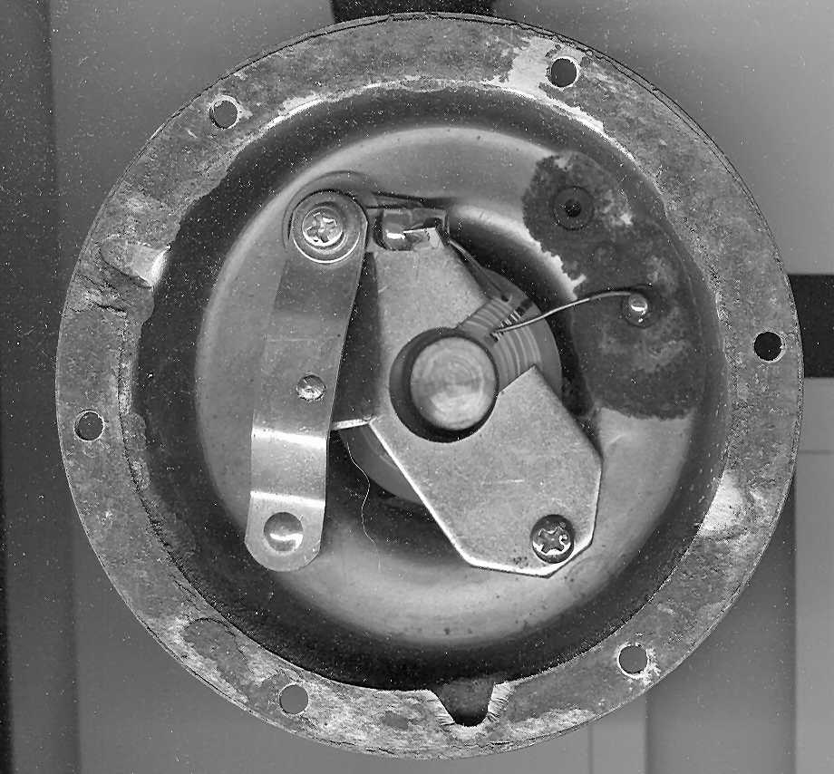
Referring to Fig. 3, remove the
screw holding the +12V connector insulator in place. Unsolder the wire from
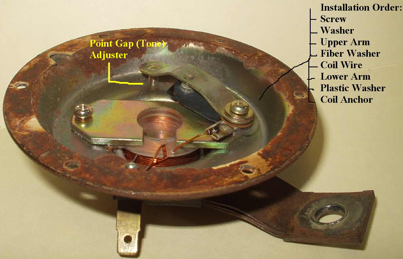
the solenoid coil to this connector. If you remove the tone adjuster (point
gap) nut and screw make sure to note how many threads are showing so you can
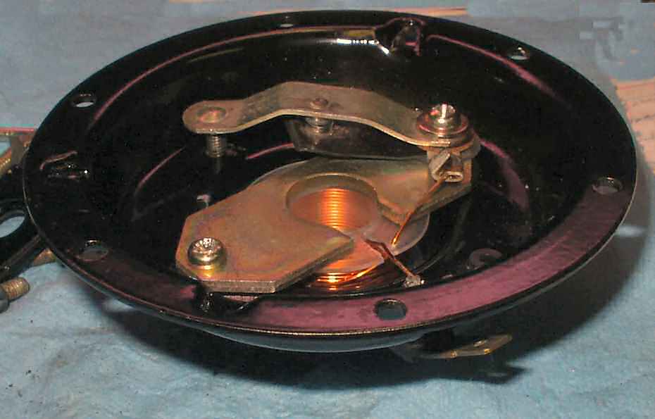
put it back the same way! Remove the screws holding the coil and armature in
place. Watch how all the little small pieces come out... (Make sure to only
do one horn at a time. You want to use the other as a guide to putting this
one back together! ) See Fig. 6-7.
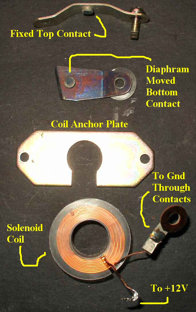
Fig. 6
Electrical Parts In Order of Removal
Fig. 7
Installed Parts
How does the Horn actually Work?
Since we have it all the way apart lets look
at how it actually works. When you press the horn button you ground one side
of the horn relay. The other side of the relay is connected to +12V through
a fuse. The relay contacts are a simple switch. One side is connected to a fused
+12V circuit and the other to the connector on the horn. When the relay contacts
close current flows from the battery through the relay contacts to to the connector
in the horn. From there it flows into the solenoid coil then to ground through
the fixed upper and lower movable point contacts (Which are now closed) energizing
it. When a solenoid is energized it creates an intense magnetic field in it's
center. If you noticed when you took the horn apart the metal diaphram has a
metal stud that goes into the center of the solenoid coil. This stud is now
drawn into the coil further due to the magnetic field. As it moves further in
the diaphram edge contacts the edge of the lower movable point contact eventually
opening the points. The instant the points open, the current stops flowing through
the solenoid coil. This causes the magnetic field to collaspe allowing the stud
to move back up which closes the points again. The whole cycle repeats very
fast. This movement of the diaphram at high speed creates a series of sound
waves that are directed through a small opening in the aluminum top cover. This
hole leads into a spiral expanding cavity that allows the sound wave to expand
rapidly eventually exiting the horn.
At this point clean up the upper and lower shells and paint
or powder coat them. I powder coated the steel half with gloss black and the
upper aluminum half with Star Dust Silver. Use a 4mm x .075 tap to clean out
the threads of all screw holes then reassemble the parts using your other horn
or these pics as a guide. Before putting the points back together use a points
file to clean them up.
Fig. 8
Top
Fig. 9
Re-assembling
Fig. 10
Homemade Gasket
Fig. 11
Completed Horn
Use the template in Fig. 11 to
make 4 identical gaskets. Click on the image to enlarge it to full size. This
is a full size uncompressed image! Select print from your browser. Make sure
your printer is set to print 100% or 1 to 1. Print the image on the thickest
paper your printer will handle. Cut out with scissors then cut out the center.
Next make the holes with whatever you can. I used a set of gasket maker hole
punches from Harbor Freight. Apply a thin coat of RTV to both sides, let dry
for maybe 5 minutes or until no longer sticky then assemble. Use a bit of anti-sieze
on everything.