If you are going to be rebuilding the Center Arm shaft you will
need to remove the center arm itself. I did not need to rebuild my shaft but
I wanted to degrease and powder coat the arm.
Fig. 1
Removing Center Arm
Fig. 2
Powder Coated Arm
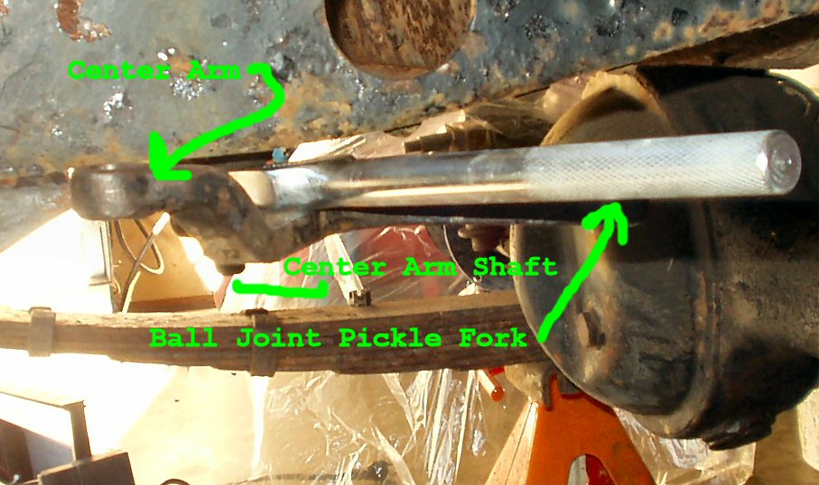
You will need a BFH and a strong jaw type Ball Joint Remover
or a pickle fork type. I used a $9.95 Advanced Auto parts pickle fork
style ball joint remover.
Insert the pickle fork between the arm and the shaft as shown
in Fig. 1. The pickle fork is not an exact fit
to the shaft but it does work.
You know the drill: Beat it till it cries Uncle! Actually
mine popped off after 4 solid blows with a 3lb baby sledge.
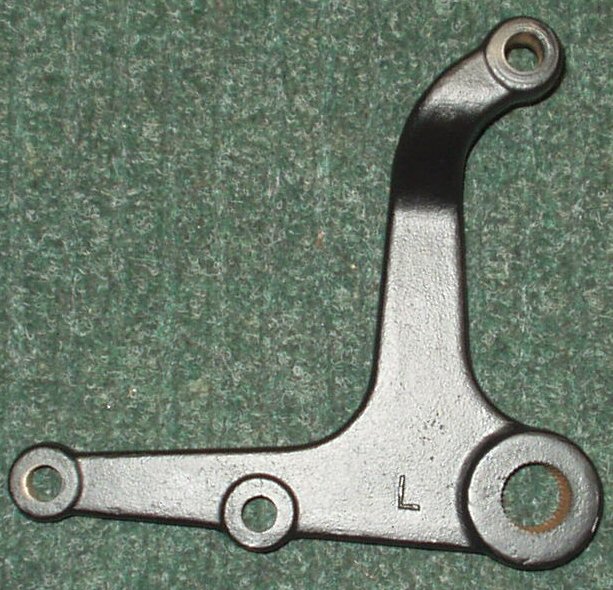
Clean it up, inspect for cracks, paint it or powder coat
it. See Fig. 2.
Removing and Rebuilding the Center Arm
Pivot
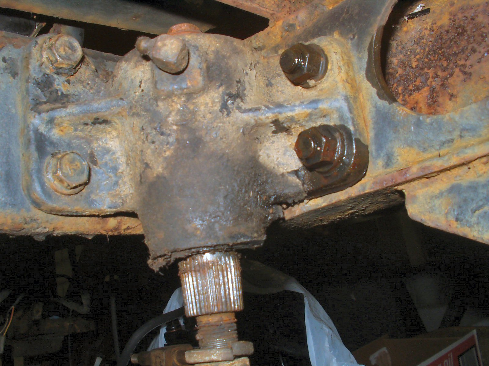
My brother (the PO) said that he had bought
the Man-A-Fre rebuild kit just a couple of years before the truck was parked.
I knew it was still in good shape so my reason for taking it off was more to
make sure he did it right and to powder coat it. I was also curious as to how
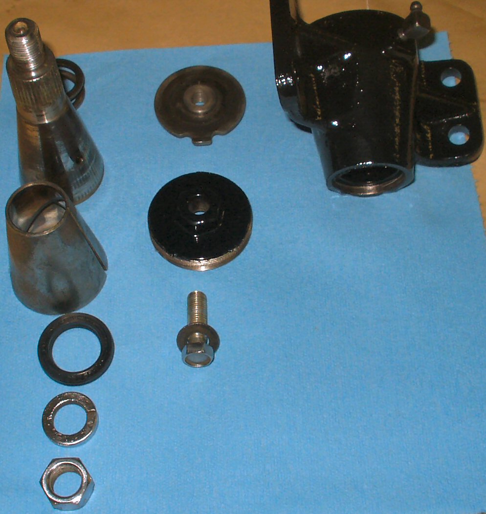
it actually worked.
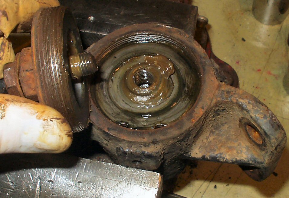
Fig. 3
What I started with
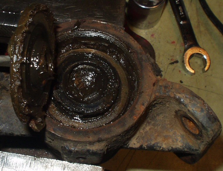
Fig. 4
Removing Top
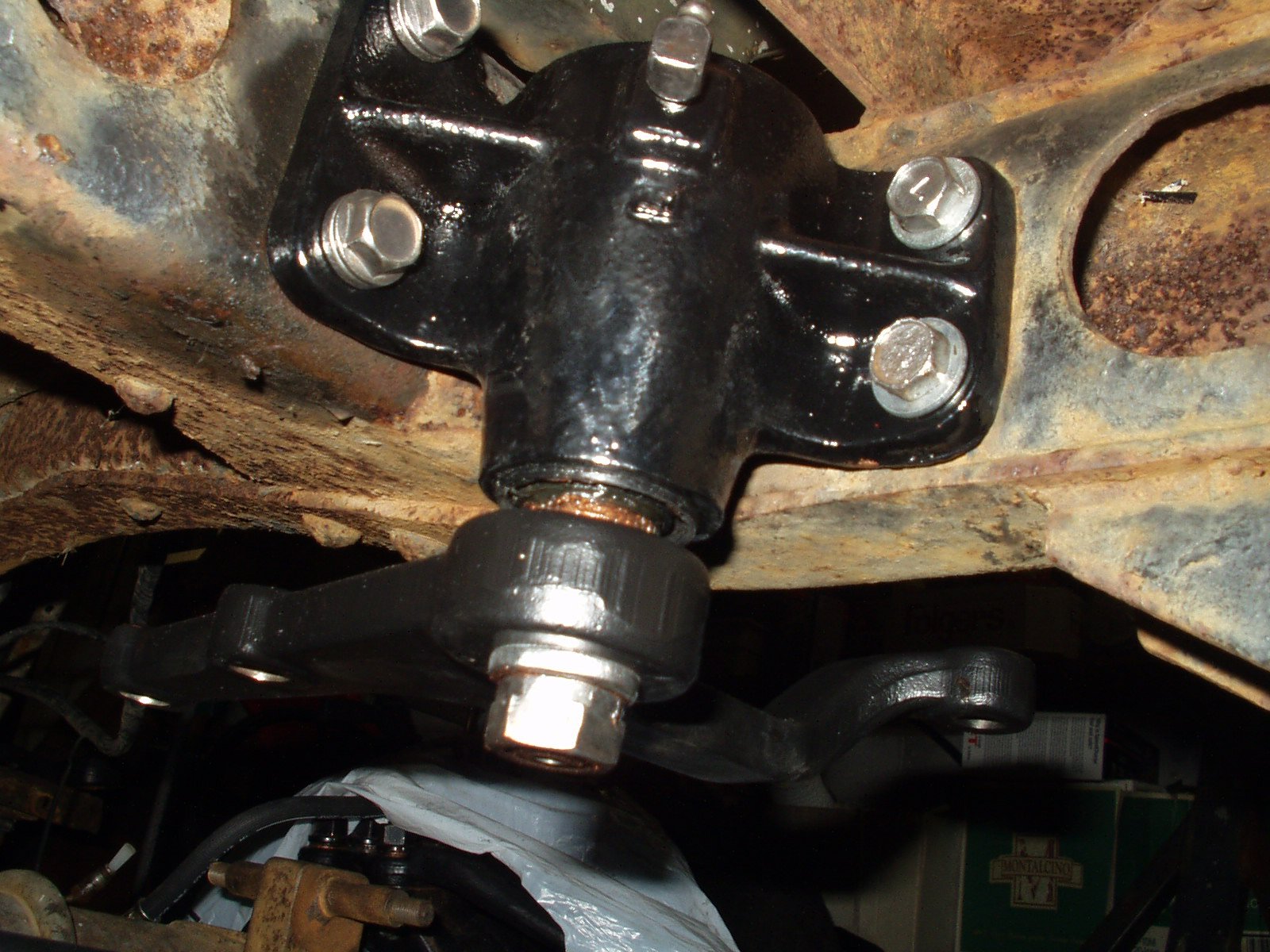
Start by removing the 4 14mm bolts holding
the Center Arm bracket to the frame. See Fig. 3.
The two that go into the cross member have welded nuts on the back side.
The two that go into the frame rail are normal bolts with nuts. You will need
a 14mm wrench inside the frame rail to hold the nuts.
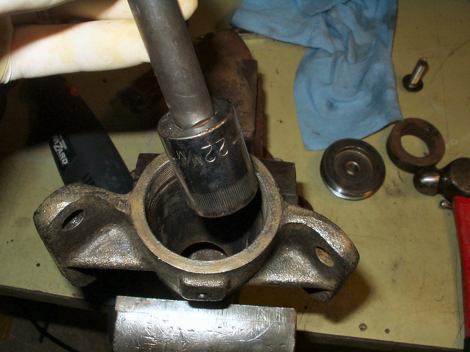
Once the unit is off clamp it in a vice as
shown in Fig. 4. Use a 14mm wrench and remove
the small bolt. Then use a 22mm socket or wrench to remove the main cap. This
will be rusted on and you may need to use an impact wrench. You might even
consider taking the top plate off BEFORE you take the center arm off the vehicle!
Mine came off quite easily as my brother had actually rebuilt this piece!
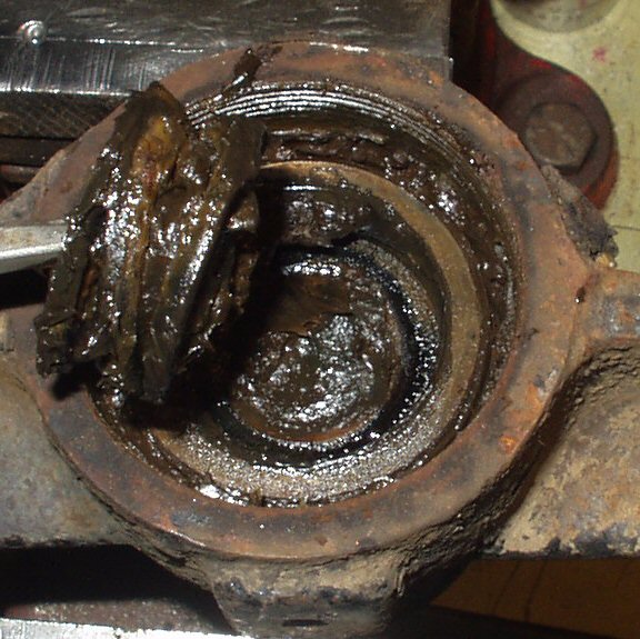
Fig. 5
Spring Plate
Fig. 6
Spring? :-)
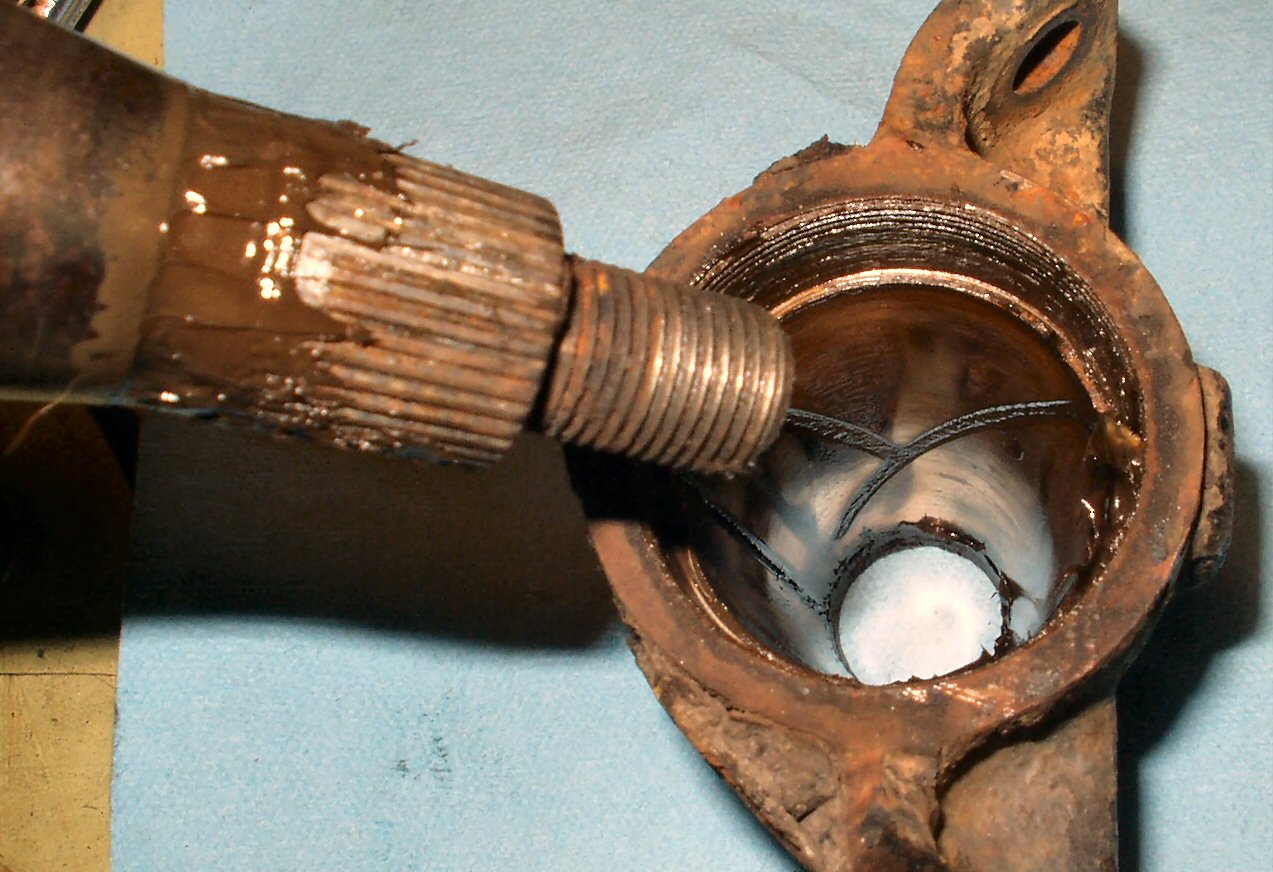
Fig. 7
Pivot Shaft
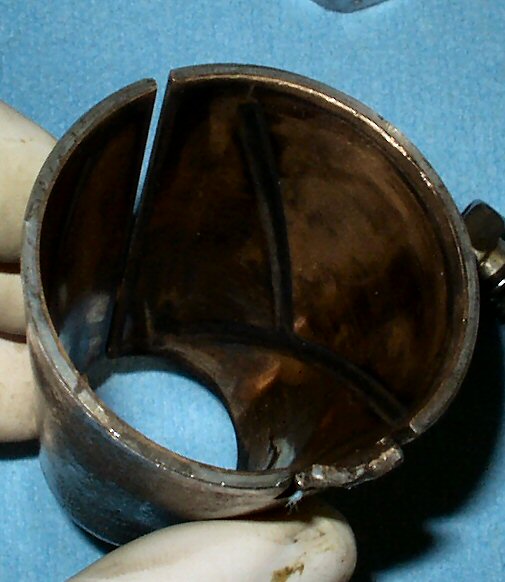
Fig. 8
Pivot Bushing
Figs. 5-8 show the
disassembly of the unit. To get the bushing out you will need to bend the
tab up (right where my thumb is in Fig. 8) I
used a small punch to bend it out.
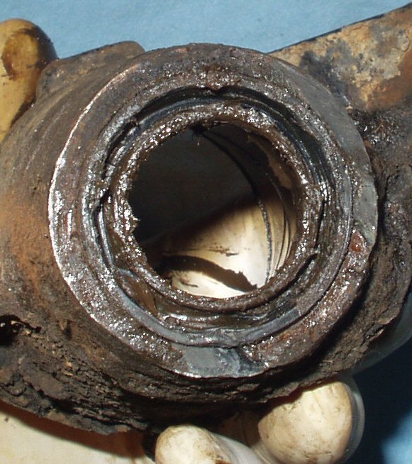
Fig. 9
Bottom Seal
Fig. 10
Driving Seal Out
Fig. 11
All Cleaned
Next put the 22mm socket on a long extension and use it to
drive the bottom seal out. Be careful! Unless you have the rebuild kit you
will be putting this seal back in! I reused mine. See Fig.
9-10.
Clean the parts in solvent to remove all the crud. Inspect
the bushing for wear. The bushing that came from Man-A-Fre has a steel outer
and the inner part is brass. I don't know but I think the stock part is all
brass. If you look closely at Fig. 8 you can
see the 'liner'.
Fig. 11 shows all the
parts cleaned. The housing has been powder coated and it's ready to reassemble.
Reassembly is simple: Use a 32mm or equivalent size socket
to drive the seal back in. Refer to Fig. 9 for
the orientation of the seal. Coat the seal lips with grease.
Coat the inside of the cast housing with grease. Coat the
outside and the inside of the bushing with grease. Place the bushing in the
housing then use a small punch to bend the tab back in place.
Coat the pivot shaft with grease and insert into housing.
Push it all the way in.
Fill the cavity in the top of the shaft with grease then
place the spring in the cavity.
Place the lock plate on top of the spring so that the tab
is pointing down.
Apply anti-seize to the inner threads of the housing where
the top threads in. Put the locking plate bolt through the threaded top and
start the bolt into the locking plate. Now while holding the housing press
the bolt down to compress the spring enough to start threading the top in.
Don't thread it any further until you have it mounted back on the truck.
Use a 10mm x 1.25 tap to clean the threads of the nuts in
the cross member. Apply anti-seize to all the bolt threads.
Bolt the housing back onto the truck and tighten it down.
Now use the 22mm socket and tighten the top of the housing
down until it's snug. Back it off 1/4 turn to set the pre-load. Now tighten
the 14mm bolt until it's snug to lock the top plate in place.
Apply anti-seize to the outer splines and bolt threads of
the center arm pivot shaft and the inner splines of the Center Arm. Slide
the arm on so that the curved arm is 'up' and to the left. Put the lock washer
and nut on and tighten it firmly. That's it! You are done!