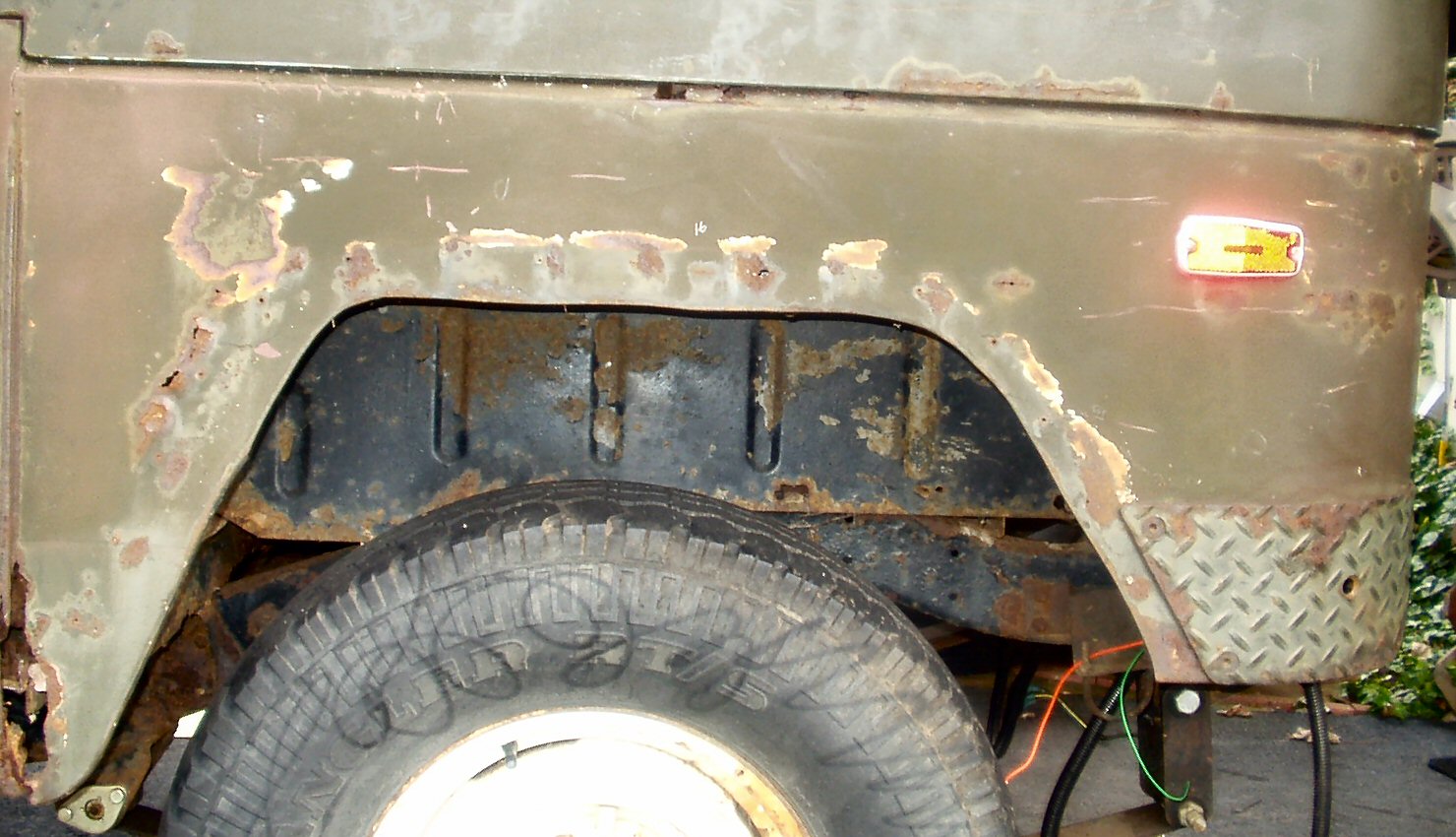
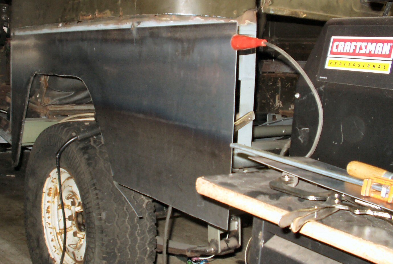
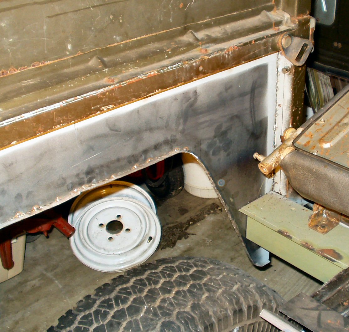
As can be seen in Fig 1,
the quarters (like the rest of the tub) were totally shot. When I ordered
the parts from the sheet metal shop to do the center channel I ordered enough
16 ga sheet to do the quarters. I had measured the length needed for the new
quarters carefully from the joint going down behind the doors to the edge
where the tail gate rests and added about 3/4" for errors. When you do
this make SURE to use a flexible tape measure! I used a cloth seamstress tape
my wife had. It follows every contour of the quarters easily. The sheet I
got was 114 inches long and 30 inches wide. I
cut it exactly in half making two pieces 57 x 30. Note: You really only need
a piece 57L x 23W inches. The metal shop just had the 30" piece handy.
Now follow along as we make a new 16 ga quarter panel.
I decided to do the drivers side first. It had less
things to do to it. It only has the side marker light, reverse
light, and tail gate clamp hooks The passenger side will have the gas tank
filler that has to be cut out of the old and welded into the new, the spare
tire carrier mounts have to be addressed, the side marker light mounted and
the tail gate hook installed. I figured I would 'practice' on the drivers
side before tackling the more complex passenger side. :-)
I started by using a square set to 1/2" resting on the
edge of the tub lip to draw a line across the old quarter panel. When cut
this will expose about 3/4" of the lower factory tub channel lip.
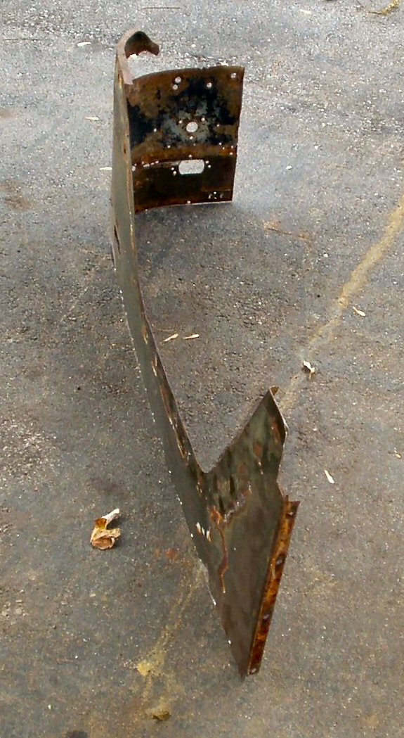
I used a cut off wheel on a die grinder to remove the old
quarter. This did not take too long. I even managed to keep the cut fairly
straight! See Fig. 2 for the old quarter panel.
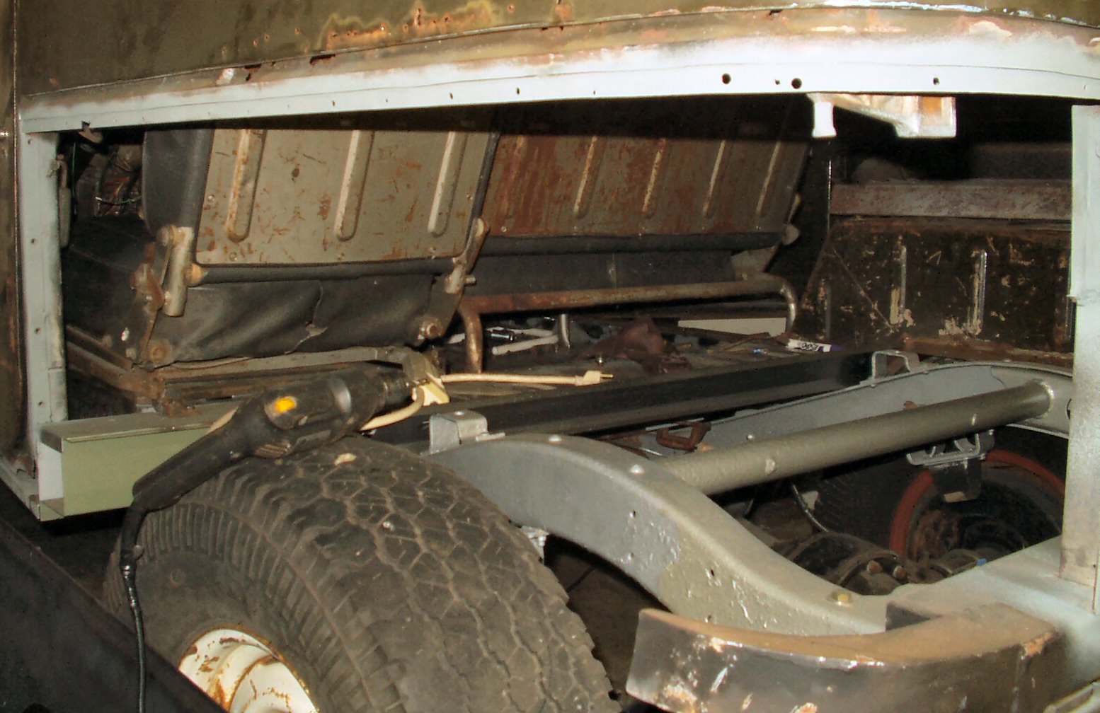
Next I used a wire brush to remove all the rust on the lip
and then primed it with a weld thru primer. See Fig.
3. Now we can start on the new panel.
I laid the new sheet across a pair of saw
horses and clamped some thick metal along each edge to stiffen it. 2 x 4's
would also work. I did not want it bowing as I worked throwing off the tracing
and measuring.
I then placed the old quarter on top of the
new sheet, aligning the front edge against one factory edge and the long
edge where I cut it from the tub along the other factory cut edge. This
ensured that I would have two known good edges to work with. One down the
line at the drivers door and one all across the top where the piece
would be welded to the tub. The other rough edge where I cut the sheets
in half would be where the quarter wraps around and would be trimmed anyway.
I allowed about 3/4" overhang anyway just in case.
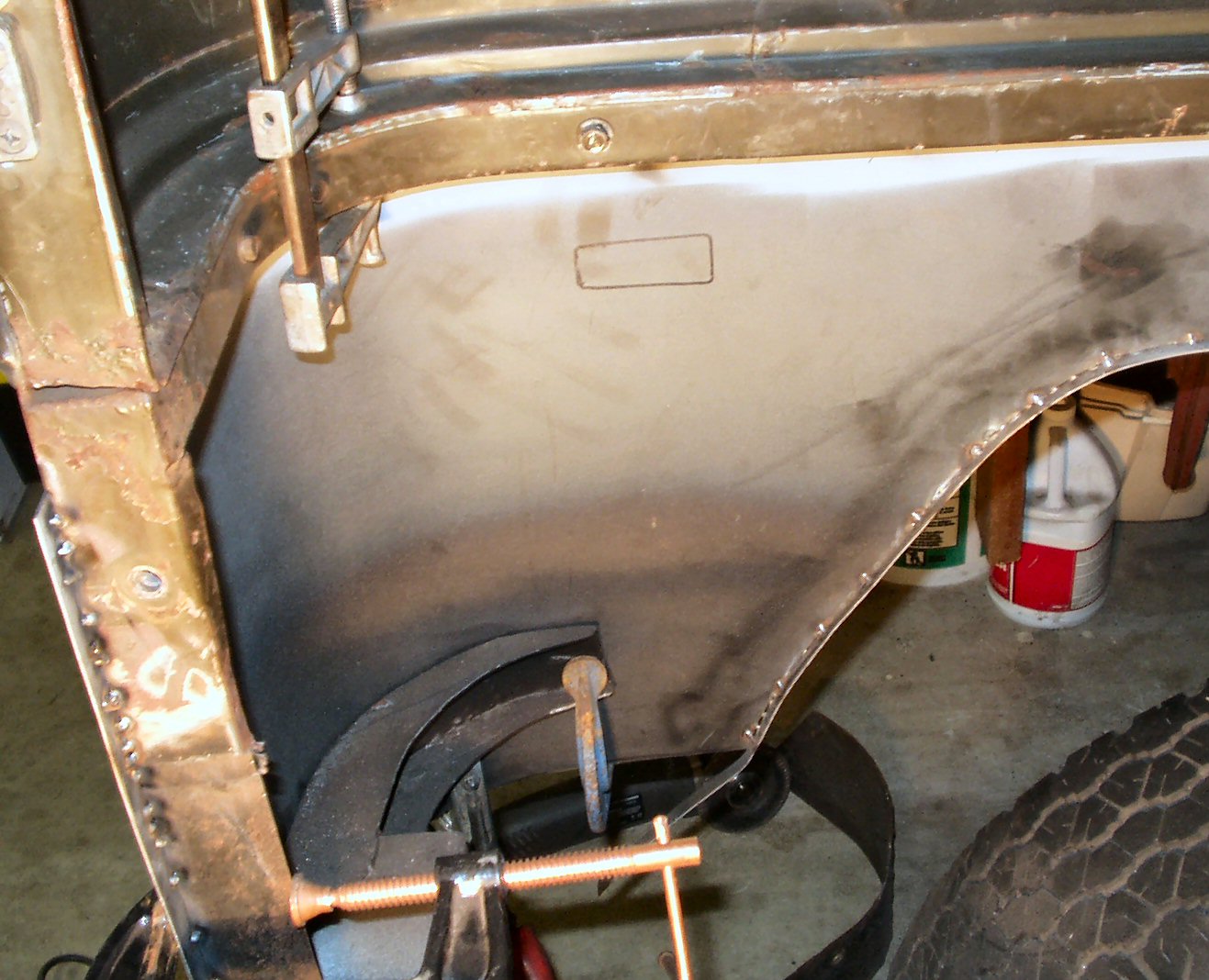
Now I used a black Sharpie and to the best of my ability
traced around the edge of the old quarter. Where it was rusted or missing
metal I stopped and started again on good metal. I also traced out the side
light cut out. Yes, I realize it will be on the inside but since my entire
cargo floor is out I have easy access to cut it out.
I removed the clamps and the old quarter and used a straight
edge to fill in the gaps in the traced line.
Now some may laugh at how I cut these out but I don't own
a fancy plasma cutter and my hand is not steady enough to use a cut off wheel
or my new air shear. The air shear works great but 16 ga is the absolute limit
of it's cutting ability. You have to push so hard that you can't get a smooth
line and curves are out of the question. However, it does work great on 20ga
or thinner. Highly recommend this if you work with thinner metals. So what
did I use? I used a cheap ass Black and Decker jig saw with a 24 TPI bi-metal
blade! Yes it took a while to do it but the edge is smooth and the wheel well
curves were easy to do. Just wear ear plugs as it is LOUD.
Once I had it cut out I laid it on top of the other sheet
that I clamped the thick metal to and clamped it down. Now I had a nice large
flat surface to work on.
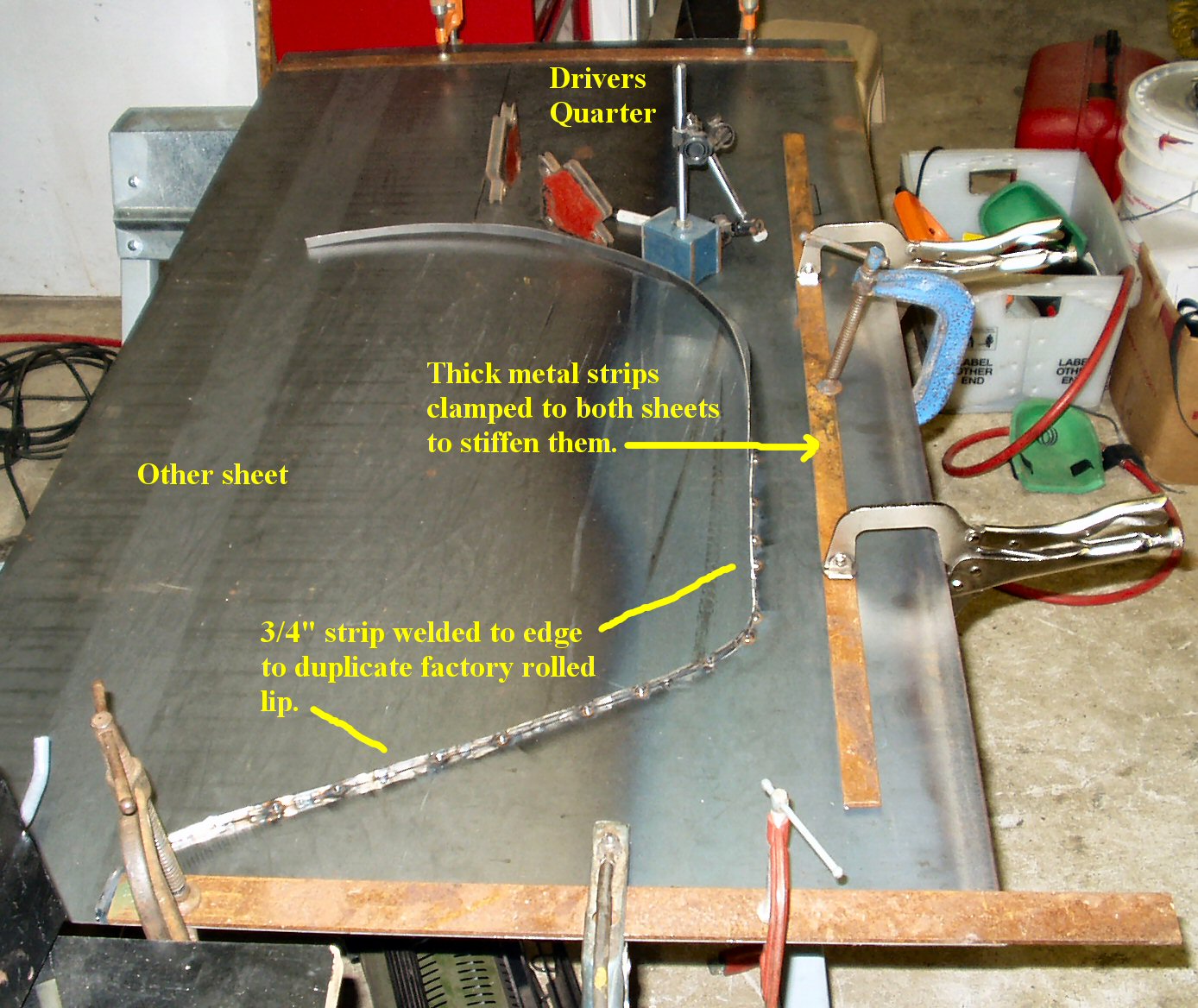
Next I used the air shear to cut a couple of long 3/4 "
wide strips of 16 ga from another scrap piece I had.
Fig. 4
Welding Lip On
See Fig. 4 Starting at the front
bottom edge where it starts to curve up into the wheel well, I tack welded
the strip to the quarter following the curve. This will duplicate the factory
rolled lip which adds significant strength to the quarter.The strip bends
very easily. Just make sure to keep it FLAT against the bottom! Don't let
the panel bow or the strip will not be straight. I just tacked it enough to
hold it. Once it is on the truck the seam is filled with welds on the FRONT.
That will allow me to grind the edge so that it looks rolled like the factory.
Now I was ready to attach the panel to the truck, or was I? Hmmm, how in the
hell am I going to get that sucker to bend around the corner evenly and smoothly?
At this point I stopped and researched on the web
to see how other folks have done this curve. A friend of mine in Virginia built
a jig using 2x4's and a large plastic roller with a radius close to that needed
to bend the metal BEFORE he mounted it to the truck. One guy says that a Cruiser
brake drum is the exact radius needed to form the curve. Another guy enlisted
a buddy to help him force the metal to bend, tack welding it around the edge
bit by bit. Well those are all great ideas but I was lacking one or more of
the necessary items to do any of those! My wife had left to go shopping (According
to her I ran her out of the house making so much noise ...) so I had no help.
(It was the Thanksgiving holiday so no friends to help either.) I also did not
have a large radius roller to build the jig so I decided that I would use the
brute force method and figure out how to bend it later.
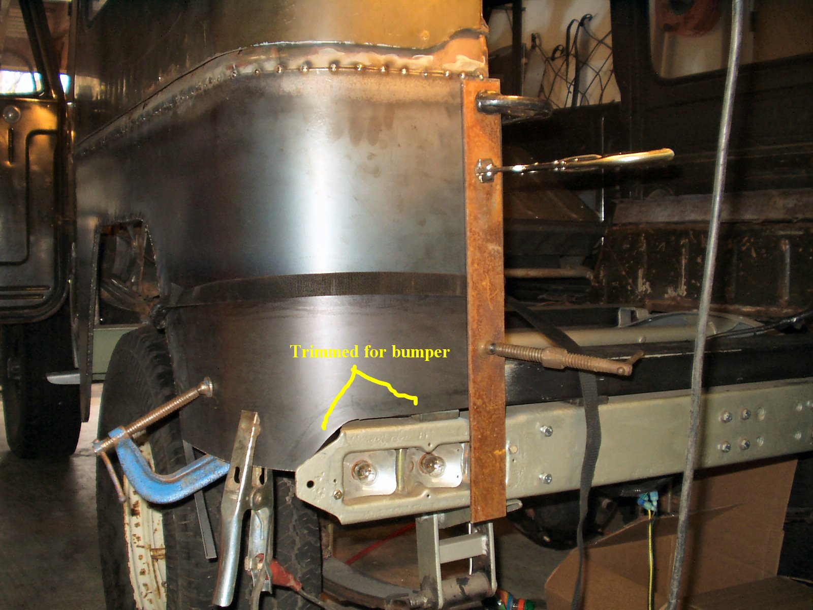
Fig. 5
Tacked in place
I used several large clamps and clamped the quarter to the
truck to see how it fit. See Fig. 5. The front
edge lined up perfectly! However the cut tub edge did not. Imagine that...
That told me that the cab had settled, the top was not square (this was a
soft top originally, the hard top was added later) or my center channel was
off. Oh well, not a problem. This is not a restoration truck!
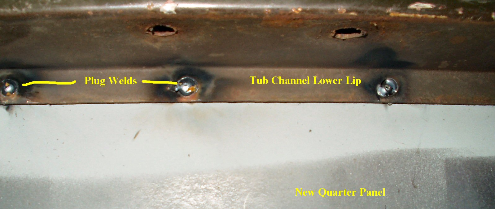
Fig. 6
Plug Welds
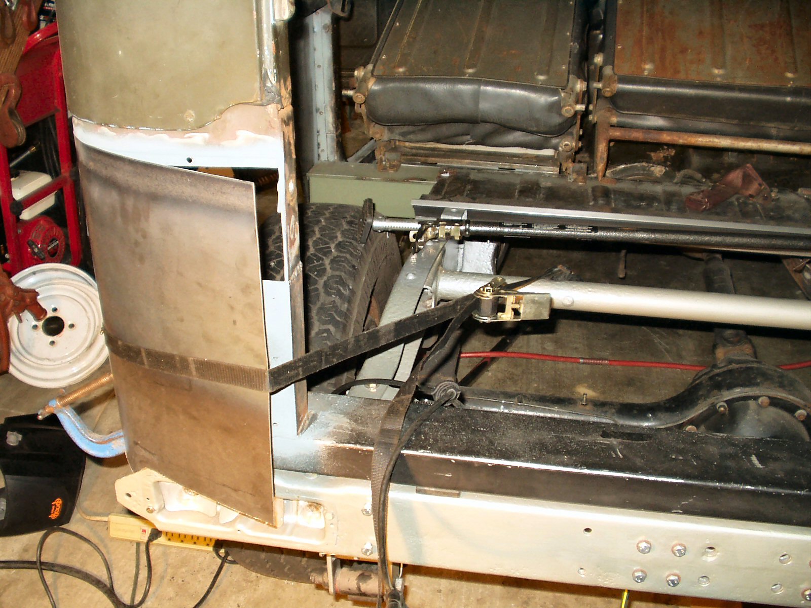
Fig. 7
How I bent the curve
Fig. 8
Another view
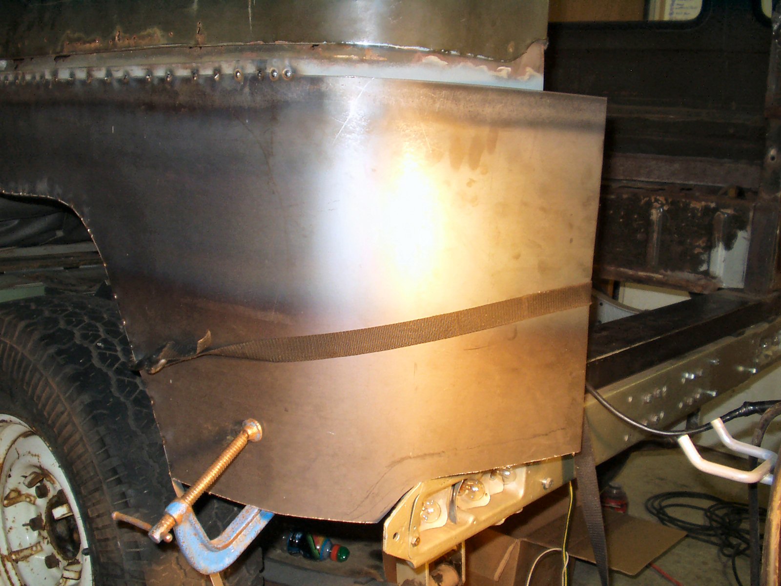
Fig. 9
Clamped ready to weld
I used a cut off wheel on a die grinder to shape the tub
to match the edge of the new quarter. This also gave me about 1/8" gap
for good welding. Next I started the laborious task of tacking the panel in.
I started by drilling out the holes for the spot welds in the tub channel
lip to 1/4". Then I plug welded the quarter to the lip from the inside.
See Fig. 6. Next I started on the outside and
working back and forth started filling in the seam. To avoid warping don't
let any one section get too hot! Just take you time and work back and forth.
Once I had the panel pretty secure I grabbed a cold one and sat and stared
at the panel just thinking about how I was going to bend that curve smoothly
by myself.
Amazing what a little alcohol lubrication will do for the
thought process! After about 20 minutes of staring at it it I had an idea...
In the past I have used ratchet straps to pull many things together. They
are strong, allow incremental movement, and are easily released. So... See
Fig. 7 and 8 for how I did it. It worked so well
that I could not believe it! The metal just curved like it was on rollers
One thing that I might mention. The edge of the quarter will cut the strap!
I placed a piece of nylon glass edge protector (came with a piece of sheet
glass) under the strap to keep it from cutting it. Once it was close to being
flush with the edge I used two more clamps top and bottom to distribute the
load. See Fig. 9.
I placed a few tacks on the edge then released the strap
so I wouldn't melt it. I finished welding the edge then ground it down smooth.
See Fig. 10 - 11.
Fig. 10
The edge
Fig. 11
Cut off and ground down
Fig. 12
Rear Inside view
Fig. 13
Front Inside View
Fig. 14
Cutting Holes
Fig. 15
Test mounting light
Fig. 16
Cleaned supports
Fig. 17
Side Marker Cut out
See Fig 12 - 13
for the inside view of the panel. I still have to finish filling in the
welds and grind it all smooth but getting there.
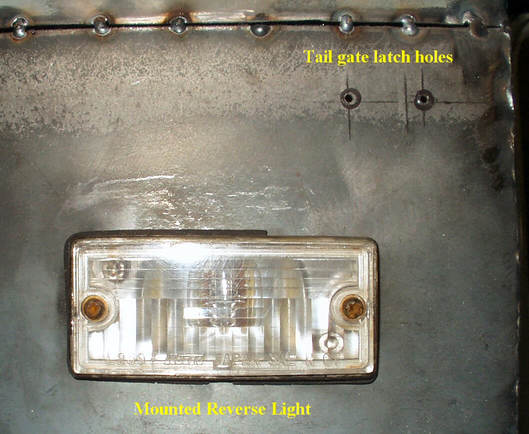
Next up is mounting the stock reverse light. Now I know someone
out there is saying, "But you have a 1974 bumper with reverse lights
built in?" Yep, but I LIKE the stock light and need to keep folks guessing
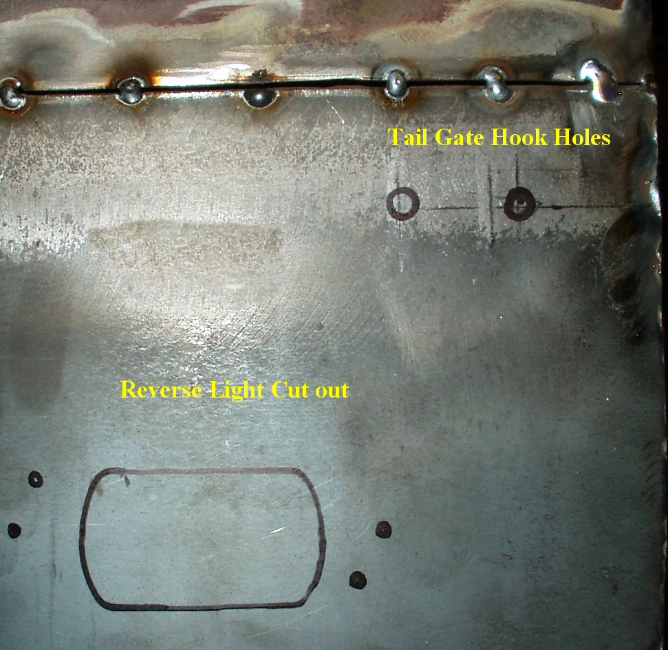
about the year of my truck! :-) From the old quarter panel I cut the reverse
light hole along with the screw holes for the tail gate hook. I used this
as a template to mark the holes. See Fig. 14.
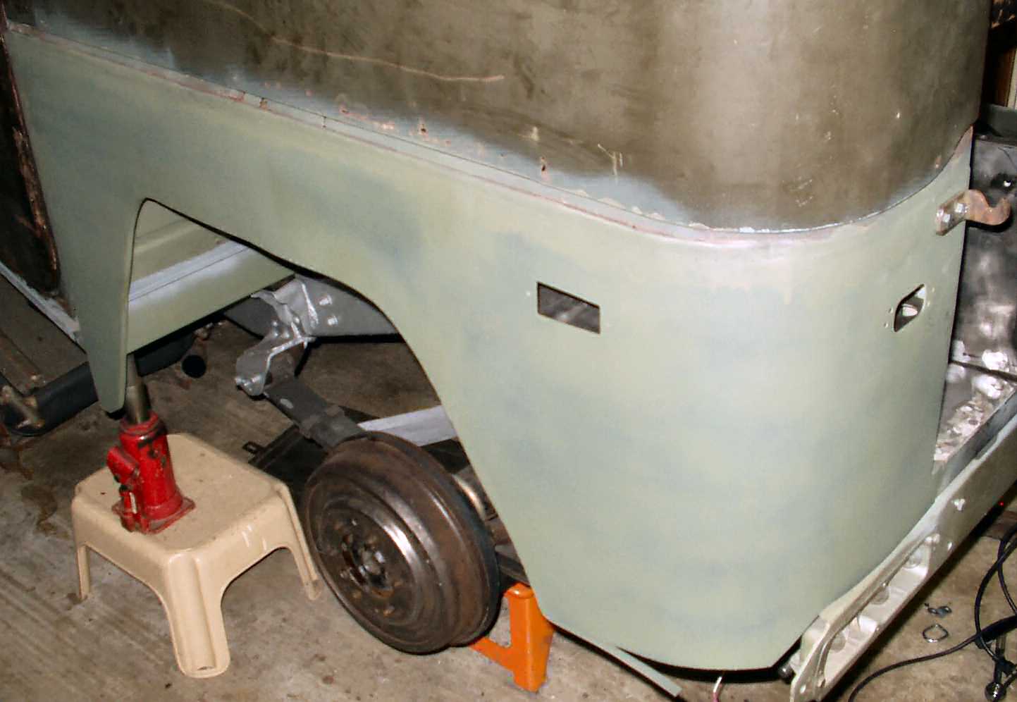
I cut out the reverse light hole with a jig saw and test
mounted the light. See Fig. 15. (Hmmm looks like
I need a new gasket for the light.)
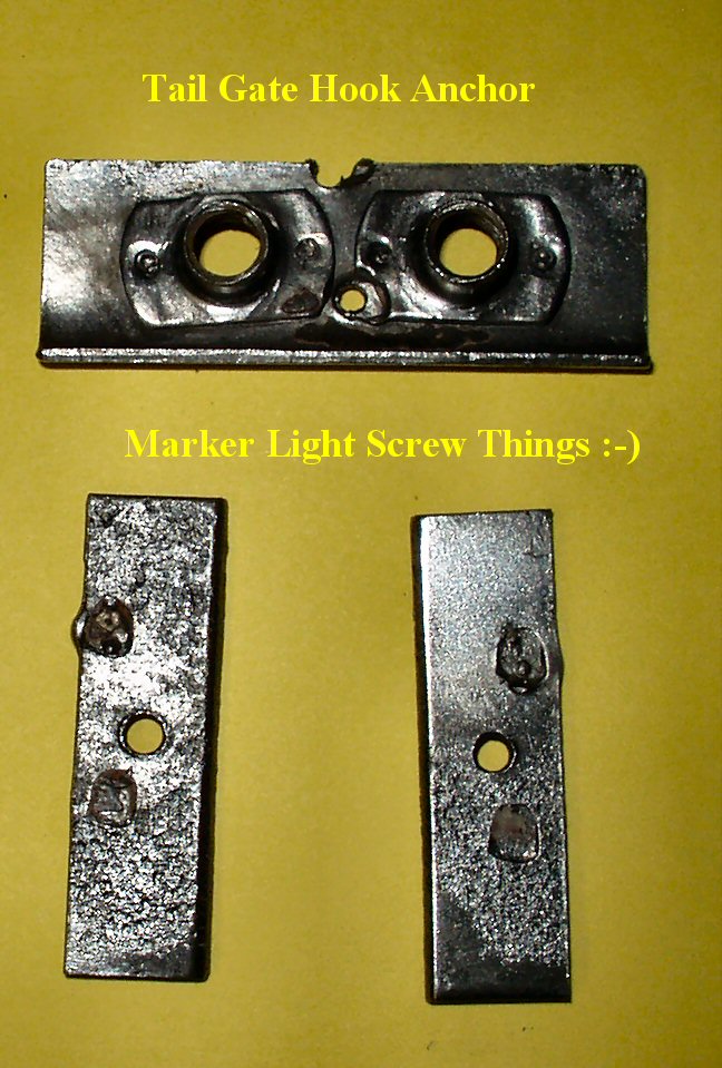
Next up I removed the threaded support backing plates from
the old quarter panel for the side maker light and tail gate latch by drilling
out the spot welds. These went into the de-rust
tank. I left them overnight then a quick wire wheel treatment and they
are good as new. See Fig. 16.
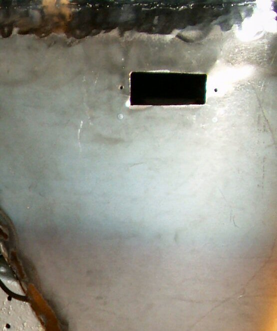
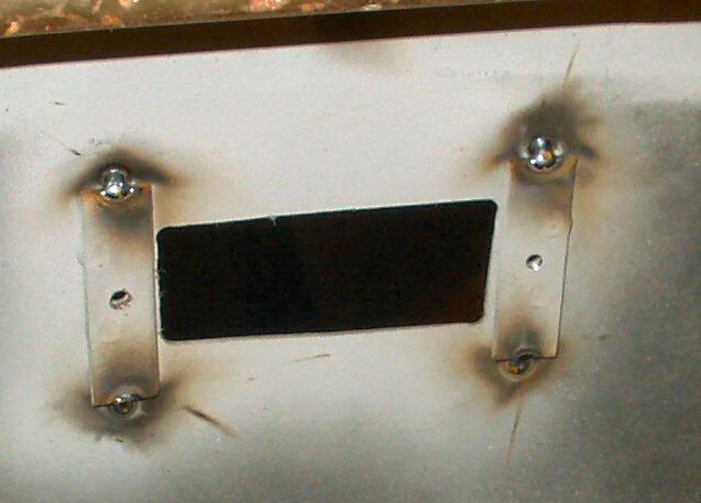
The side marker light had been marked already on the inside
using the old quarter so I cut that out with the jig saw. See Fig.
17.
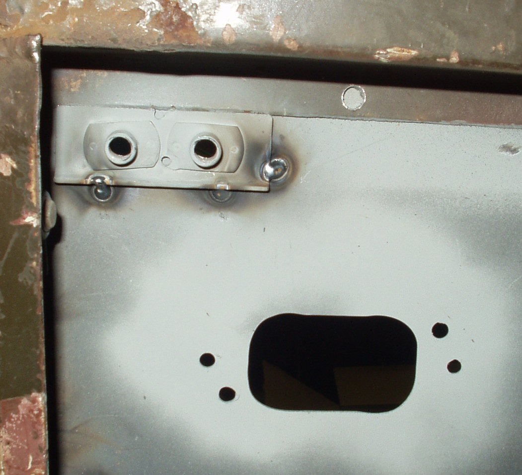
Now I could weld in the backing plates I cleaned up. See
Fig. 18 - 19.
After filling in all the weld gaps, plug welding it to the
center channel, and flap wheel grinding
it all down, here is the finished product. See Fig.
20.
It will need a bit of filler along the seams, but again, this is not a resto!