This mod is for those whose T-Case output shaft
has a bad groove worn in it, and a new seal does NOT stop the oil leak. This
mod adds a second seal that will ride in a new location on the shaft eliminating
the leak.
Since my Emergency Brake Drum has a slight groove in it I decided
to try this mod. It was much easier than I thought it would be, just a bit time
consuming.
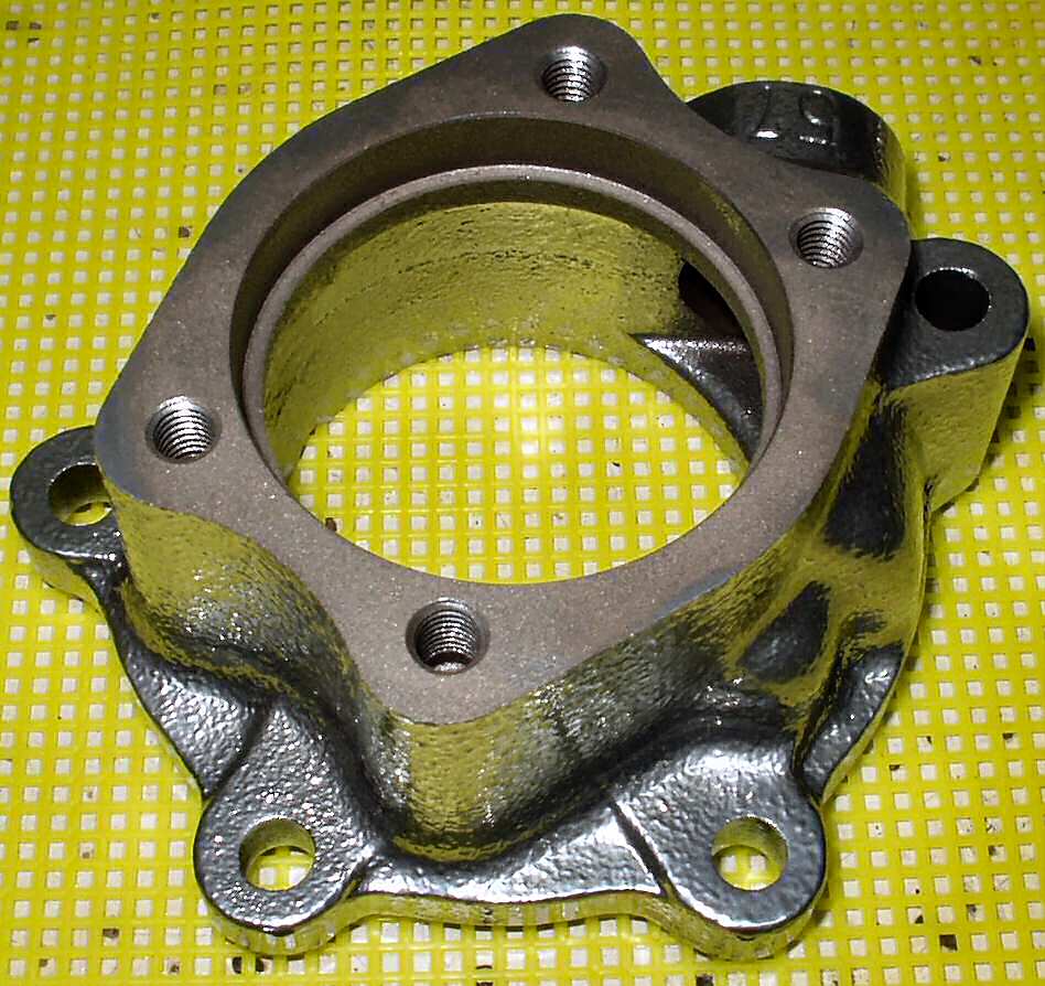
Fig. 1
Coated Speedo Housing
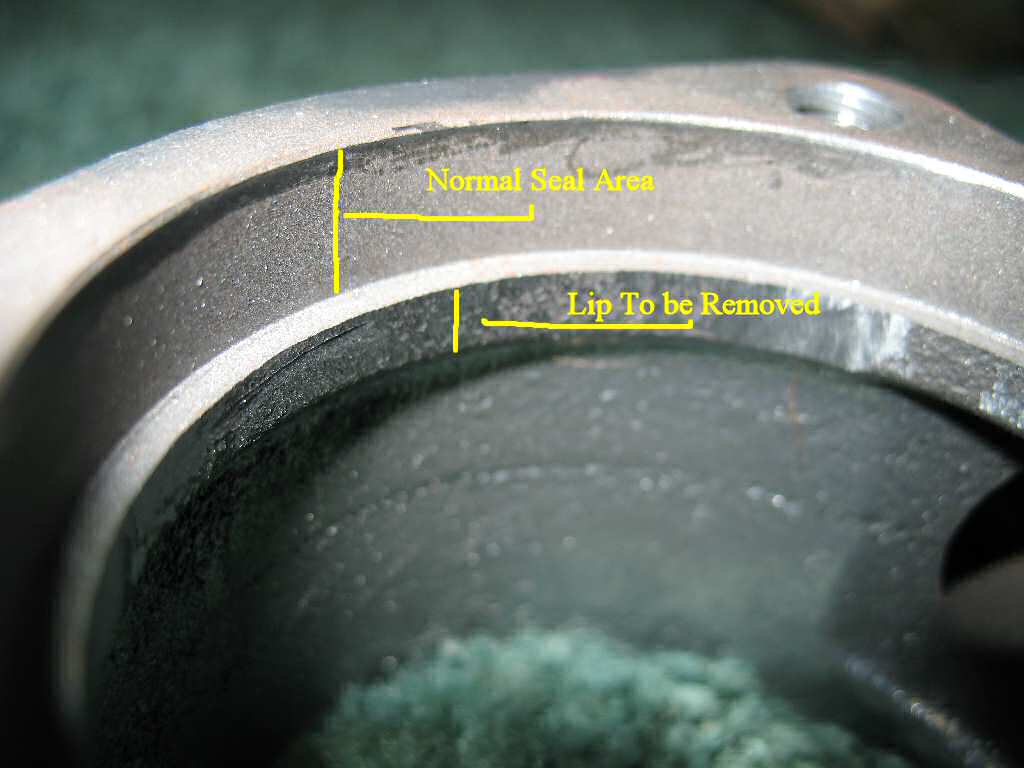
Fig. 2
Lip to be Removed
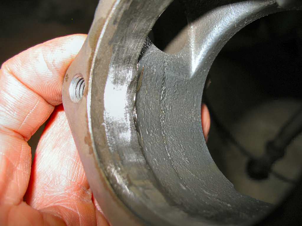
Fig. 3
Lip Removed
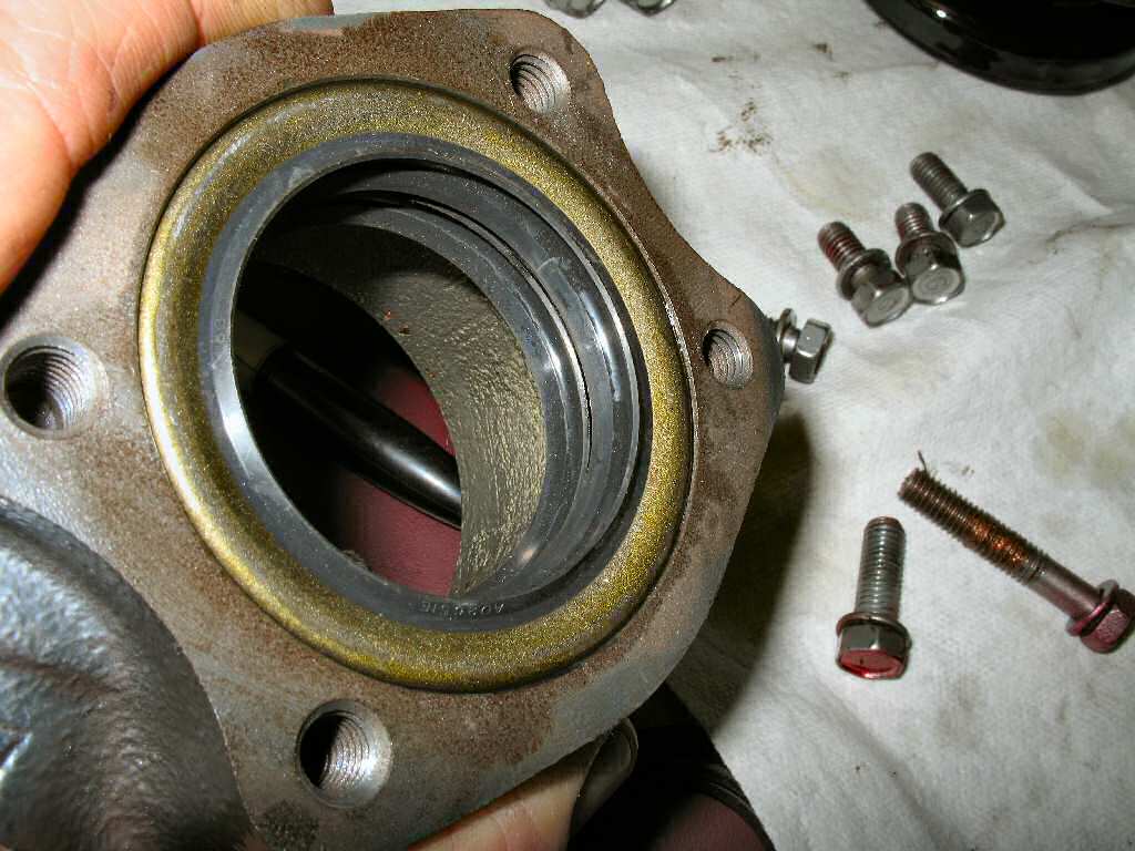
Fig. 4
Seals Installed Front
Fig. 5
Rear View
Fig. 6
Greased Lips
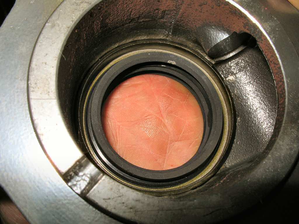
Fig. 1 shows my nice
cleaned and powder coated speedo housing ready to be hacked on!
The stock seal sits flush with the machined surface of the
speedo housing. The seal is kept straight in the bore by a lip as seen
in Fig. 2. It is this lip we will be removing.
So how will we keep two seals straight in the bore? Careful insertion.
I used a Dremel tool with a 1/4" carbide bit to slowly remove
the lip. Don't expect this to remove material easily! This is a cast IRON
housing, NOT aluminum. Take your time, you don't want to remove too much
material.
Fig. 3 shows the finished job. I finished it by putting
a fine grit sanding drum on the Dremel to smooth it up.
Get your two seals (AD2651E), coat the seal outer shells
and speedo housing seal seat with oil. I used a plastic faced hammer and
carefully started the first seal in keeping it square in the bore. I drove
it flush with
the
machined
surface.
I placed the second seal directly on top of the first seal
and start driving it in. It takes harder whacks since you are actually driving
two seal at once. Continue to monitor the seals so they don't get cocked
in the bore! Drive the second seal until it's also flush with the machined
surface. That's it! See Fig. 4 for a front view and Fig.
5 for a rear view
of both seals installed.
Fill the seal lips with grease to provide lube for the front
seal which should not receive much lubricating oil. See Fig.
6.
Fig. 7
Driven Gear and shaft sleeve
Fig. 8
Inside O-Ring
Fig. 9
Driven Gear Size Stamp
Fig. 10
Drive Gear Size Stamp
Fig. 11
Speedo Cable End Parts
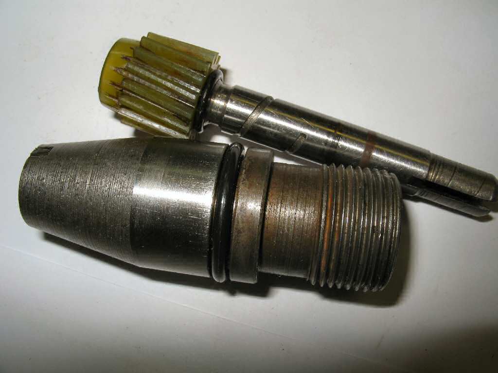
See Fig. 7. Get the speedometer driven gear, and speedometer
shaft sleeve. Again wash the parts in hot soapy water, rinse and blow dry.
Install a
new rubber O-ring on the shaft sleeve.
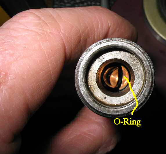
Using a dental pick remove the small
o-ring from the machined groove INSIDE of the shaft sleeve.
Install the new o-ring. See Fig. 8.
If your tires are larger than stock and just happen to be
33" this is an excellent time to recalibrate your speedo. Order the
following from C-Dan : 33403-60030 (16 tooth) driven gear and match it
with a 33481-60030
6x17 drive gear (which is what came in my transfer case). See Fig.
9-10 to
see where the size is stamped.
Do NOT install the speedo gear back in the housing until
AFTER you set the pre-load on the output gear! It's possible to strip the
gear if you turn the shaft backwards while setting the pre-load.
Fig. 12
Shim,Gear,Spacer
Fig. 13
Housing Installed
Fig. 14
Torquing E-Brake Drum
Fig. 15
Testing Pre-Load
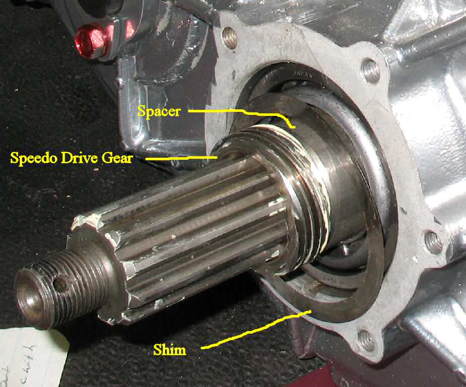
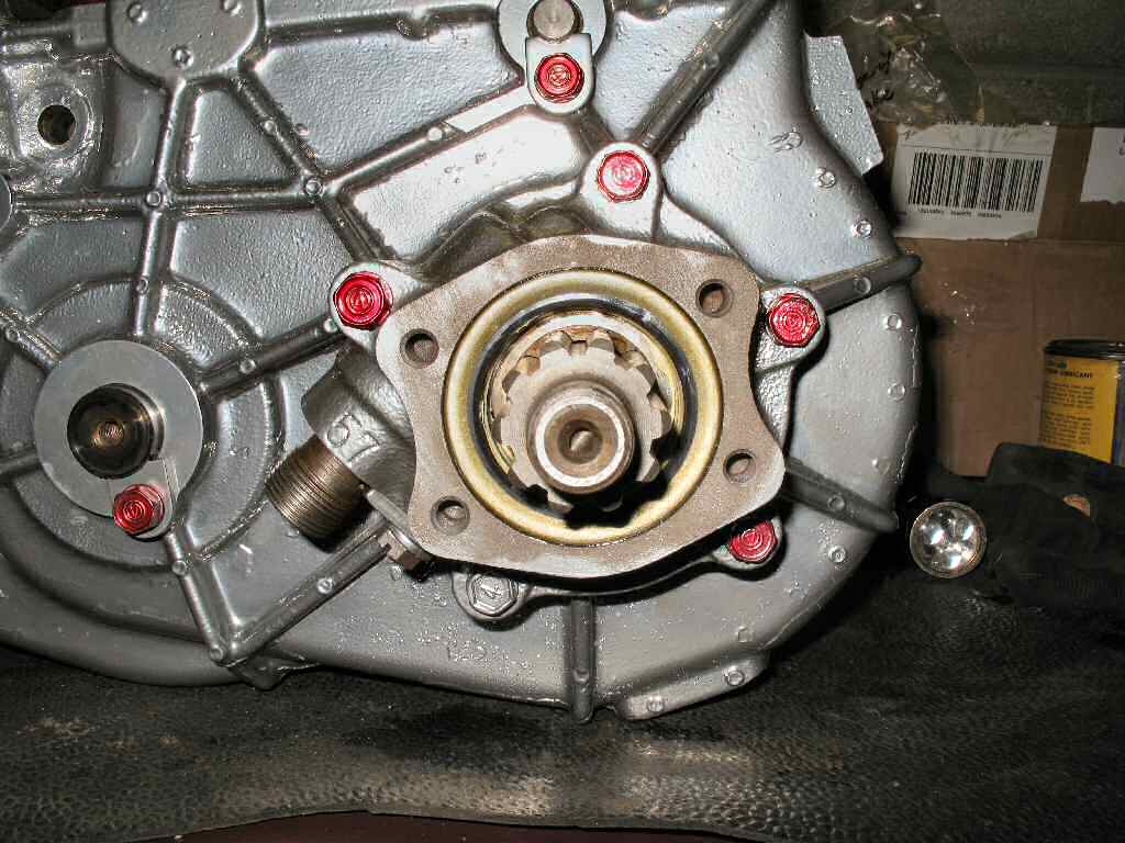
Locate the shim, Speedo drive gear
and spacer and install on the shaft as shown in Fig.
12.
Get the gasket for the speedo housing and trim it to fit
if necassary. Coat the gasket on both side with blue RTV, place it
over the housing, put the shim in place then place the housing over the
output
shaft. Install the 5 8mm x 1.25 bolts. Tighten to 7 to 11 ft lbs. See Fig.
13. It's important to get these bolts to their proper torque!
They are what help set the pre-load on the bearing NOT the e-brake drum
nut torque!
Temporarily install the parking brake drum and tighten the
retaining nut to 101-123 ft lbs. You will need to use a big wrench jammed
in the drum studs to hold the shaft while you tighten it. See Fig.
14.
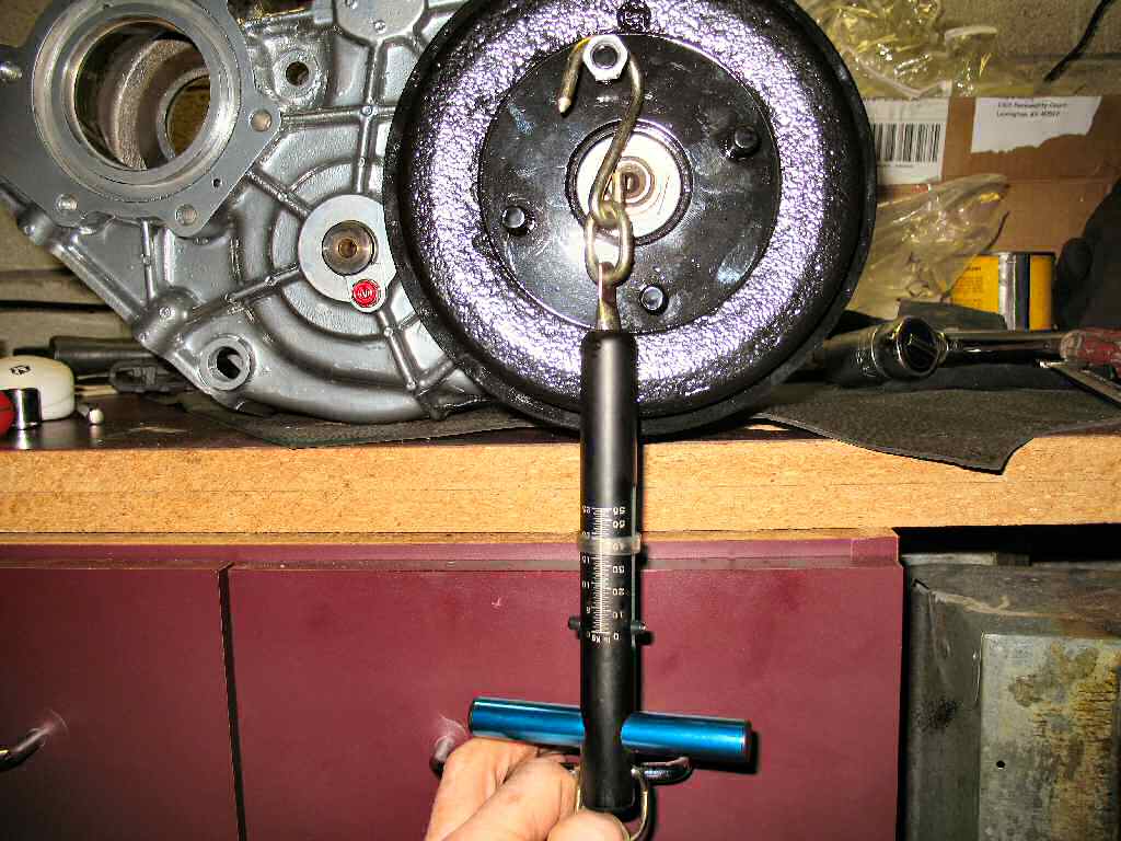
Place the transfer case into neutral
and disengage the front drive.
Refer to Fig. 15 and attach
a spring
scale
to a
drum stud
bolt set at about 11:00.
Pull
on the scale with an even force. It should take 10-13 ft lbs to start the drum moving. Repeat a couple of times to verify the reading.
If your reading is lower than 10-13 ft lbs you will need
a THICKER shim. If it is higher than 10-13 ft lbs you will need a THINNER
shim. You will need to pull your shim and measure it to see which way
you need to go. My shim was measured at .008. Any Toyota dealer can get
the shims. The shims are available in the following thicknesses.
Part No.
Thickness
90564-64017
0.10 mm (0.0039")
90564-64023
0.015 mm (0.0059")
90564-64024
0.20 mm (0.0079")
90564-64025
0.25 mm (0.0098")
My measurement was 5 ft lbs so I needed to order a thicker
shim. I just ordered the three I did not have from the set so I could
mix and match. I ended up with .008 and a .0039 shims to get the proper
pre-load.
Insert the driven gear into the sleeve after lubing
it with some 90W. Install the shaft sleeve back in the speedo housing
and install the retaining bolt and washer.
Final notes: The transfer gears, spacers and PTO gear
if used will be installed when you mount the T-Case back to the tranny.
See Page 35.