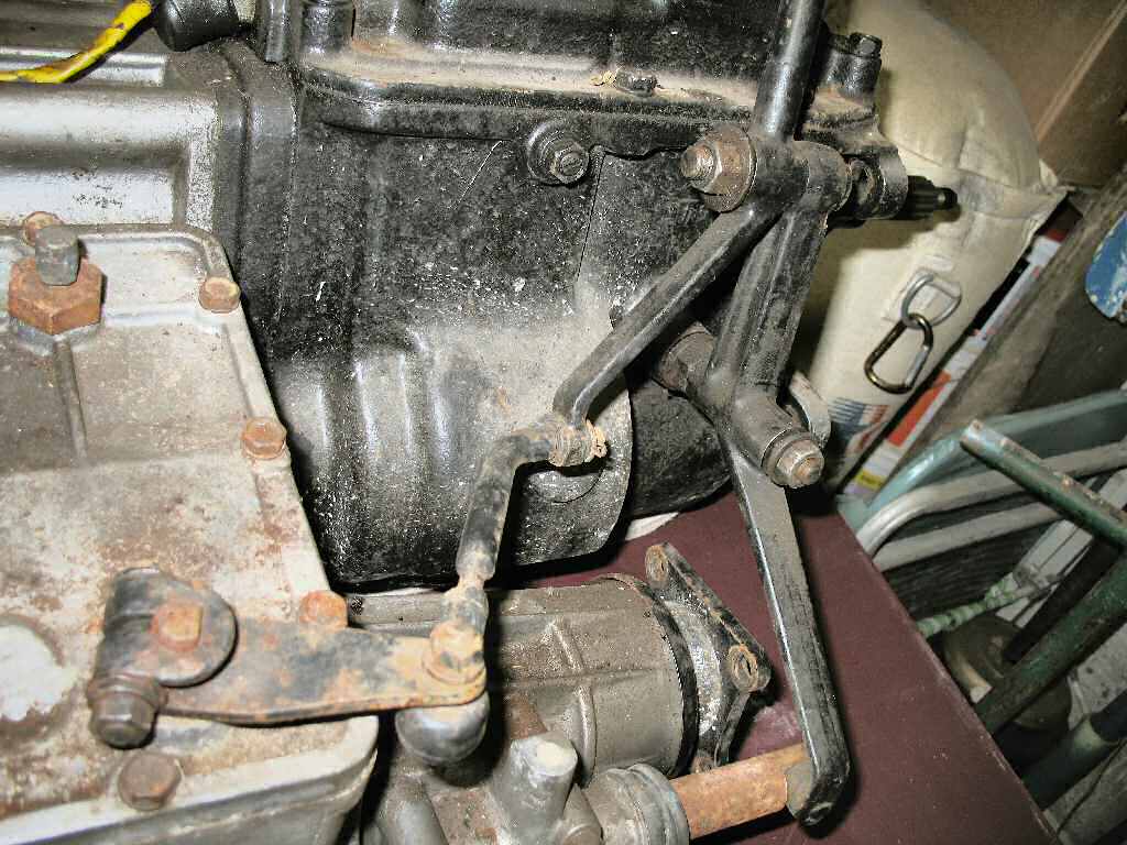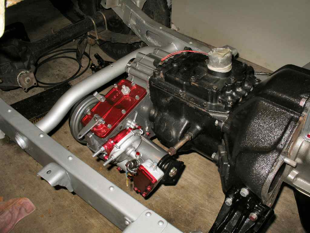
Fig. 1
Day I got it
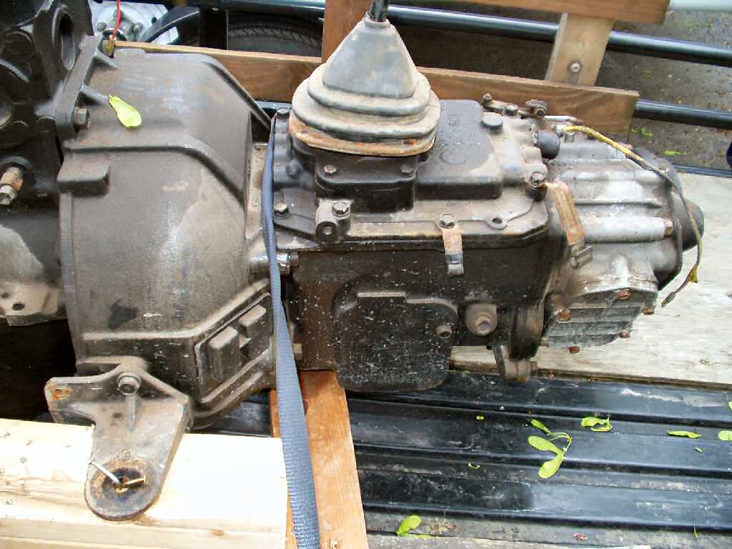
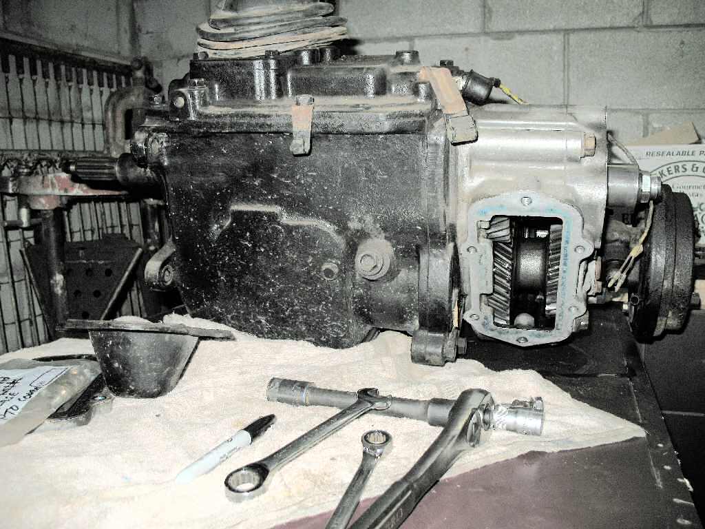
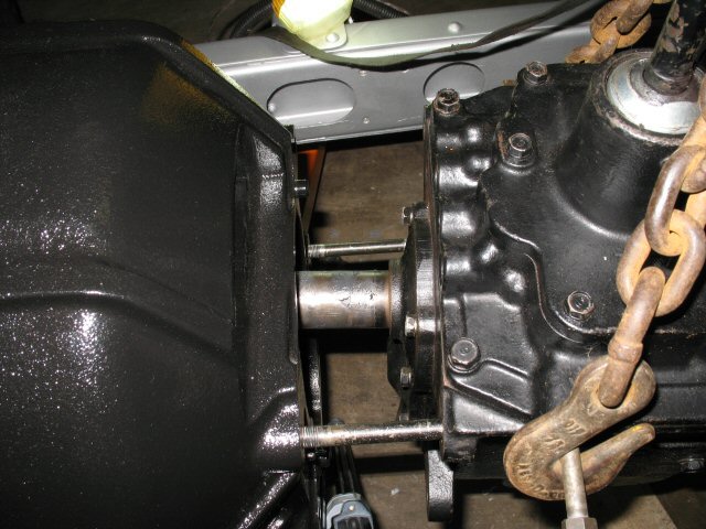
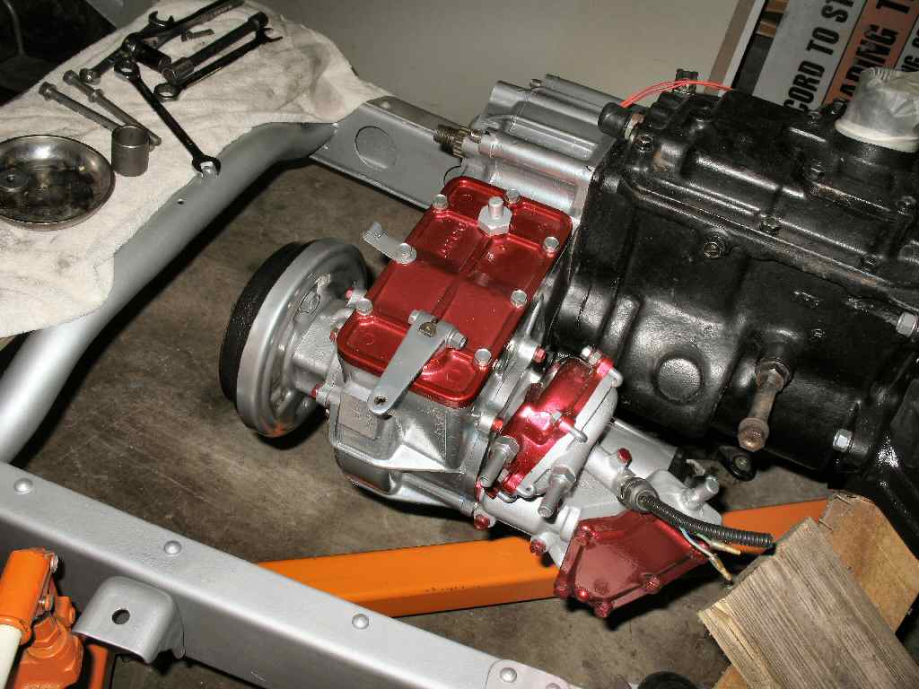
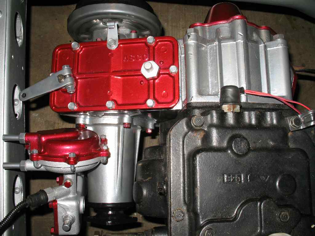
Fig. 2
Pretty Clean
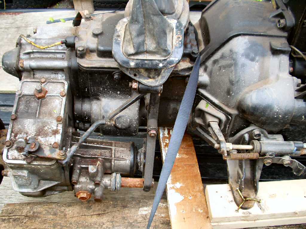
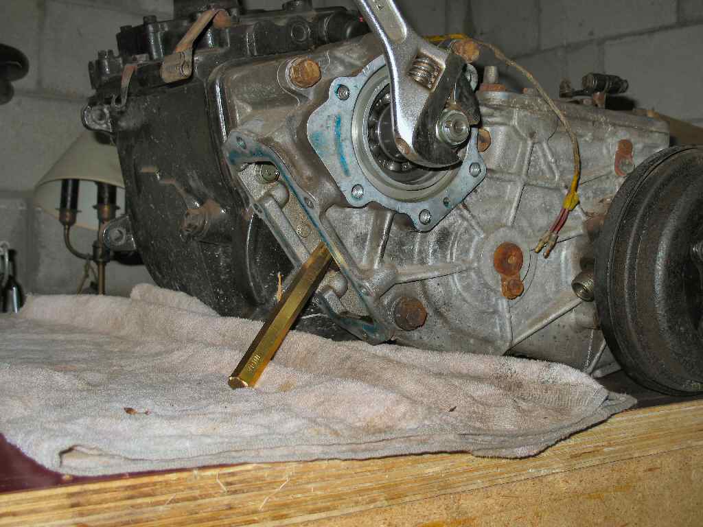
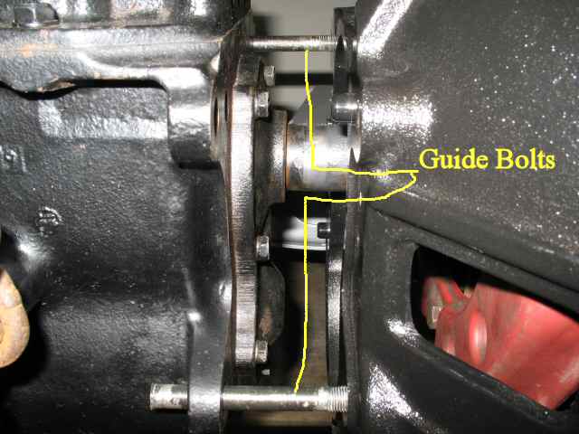
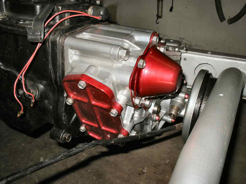
Fig. 3
All Linkage here
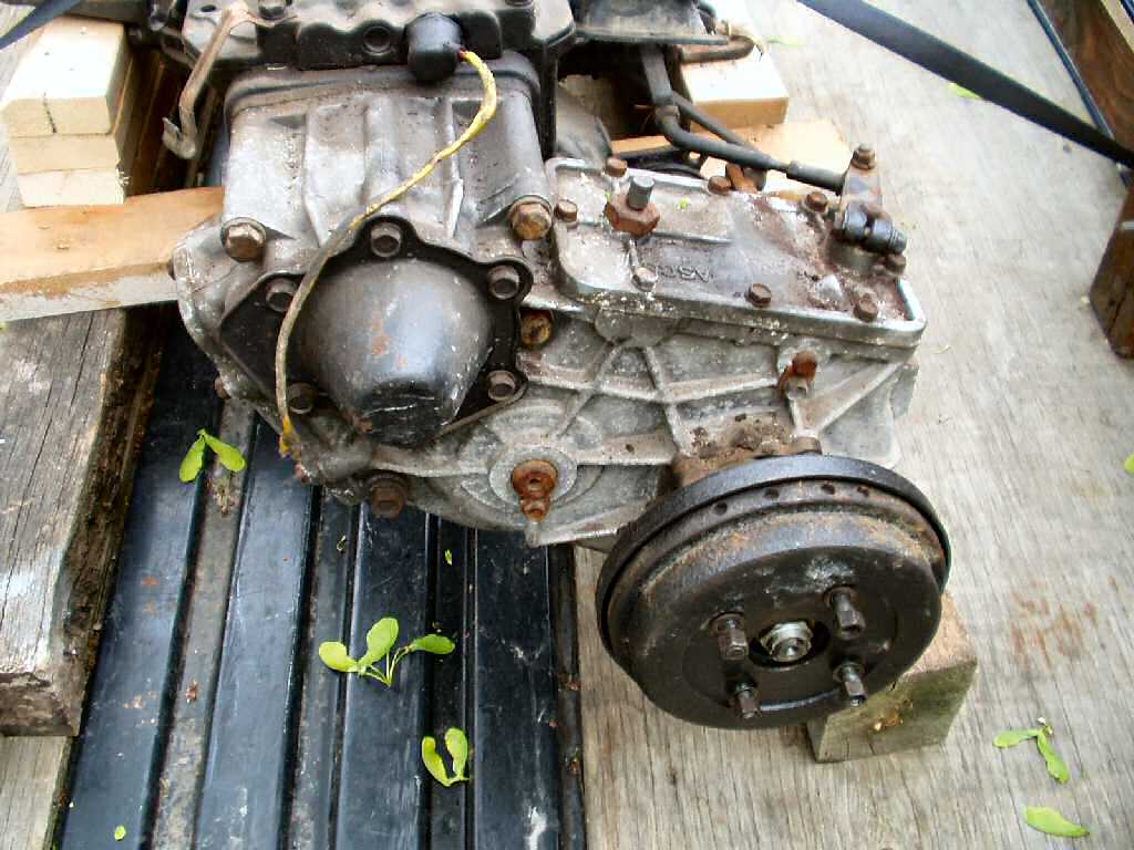
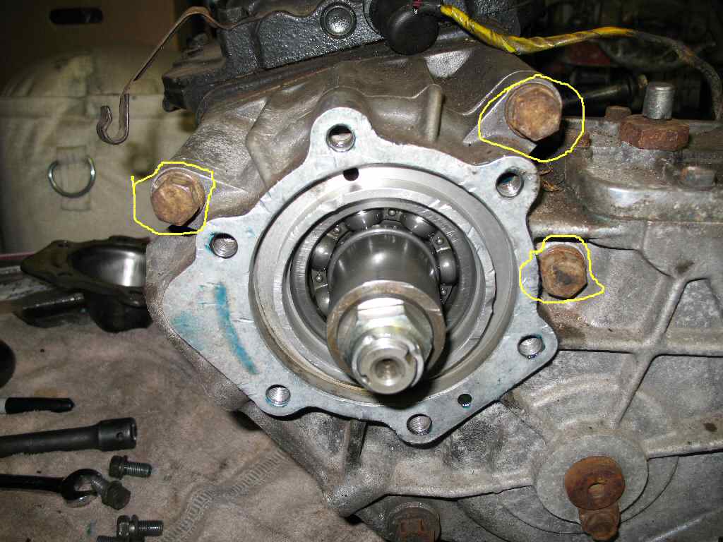
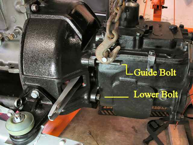
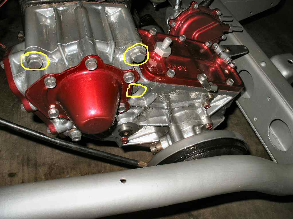
Fig. 4
Complete E brake
Fig. 1 Day I got it |
Fig. 2 Pretty Clean |
Fig. 3 All Linkage here |
Fig. 4 Complete E brake |
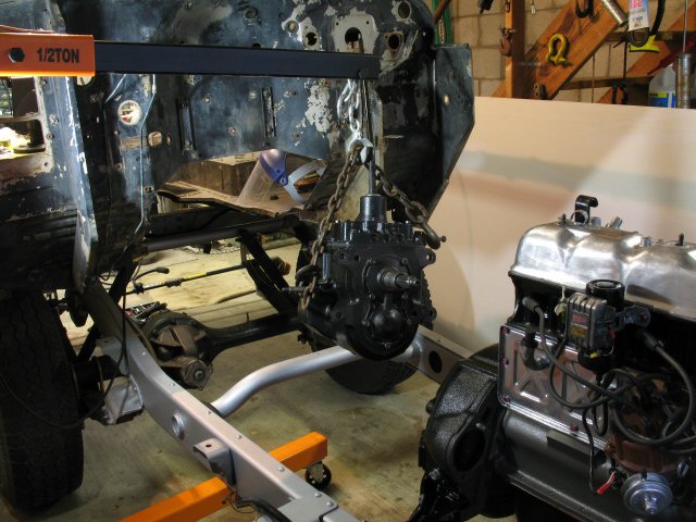
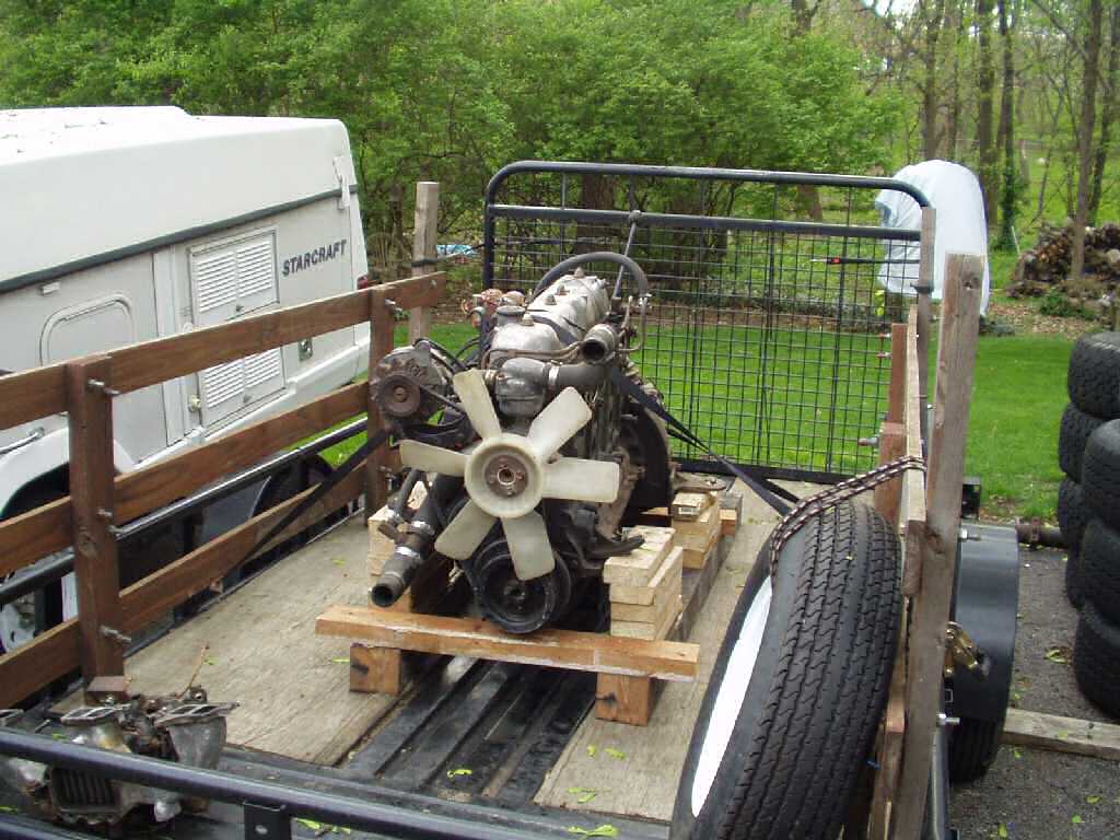
Look what I brought home! Picked this up in northern Ohio for $500!
My long term plans are to build the 2F engine up slowly while I drive the F engine I have, then do an engine swap. For now I'm going to convert my truck to use the 4 sp tranny with my 3sp t-case. This will involve locating some parts. In the meantime, under a tarp it went...
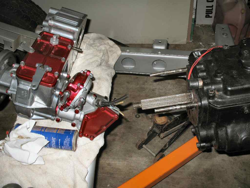
I'm finally to a point in this where I needed to pull the tranny/t-case from the engine. So I got the engine hoist out, hooked a chain around the tranny, took the weight off the engine, removed the 4 bolts holding it in and started pulling. I expected to have to beat, cuss and get my blood pressure up trying to get this free, but suddenly got a great idea to get it loose. I had ordered a set of aluminum shims from CCOT for the front axle to help with the longer shackles. These make PERFECT wedges for separating the tranny from the block! I started tapping them in with a rubber hammer and POP! the tranny slide right out! I transferred the combo to a rolling cart and wheeled it into the basement where it was placed on the work bench cleared off just for this job.
Ok so now I have both cases on the bench, it's time to start gathering the parts I will need to do this swap.
The following parts will be needed to make the 3 sp t-case work with the 4 speed tranny:
Part Needed |
Sources |
Cost |
Notes |
| 29 tooth 16 spline input gear | MudRack or late 73 to 74 4 sp t-case | 55.00 | (transition gear is common name) the normal input gear in a 75> 4sp is a 31 tooth and will NOT fit the 3 sp T-case. |
| PTO gear or gear spacer | MudRack or 4 sp t-case with PTO option | 55.00 | Any 4 speed t-case will have the spacer you need |
| 1974-1982 Datsun B210 pickup truck rear axle bearing Part #RW114R | Advanced Auto Parts | 49.88 | This bearing allows the 3 sp t-case housing to accept the 4 sp input shaft. It's outside diameter is the same as the 3sp and the inside diameter matches the 4 sp tranny output shaft. |
| Pilot Bearing SKF #6202J | Advanced Auto Parts | 10.99 | |
| COMPLETE t-case shifting linkage from the 4 sp | Donor 4 sp tranny | Use this if using the t-case floor shifter | |
| Optional: Front and rear Drive shafts from a 4 sp FJ40 | Donor 1976-up FJ40 | Not completely necessary but using them will keep you from having to lengthen your front 3 sp shaft and shortening your rear shaft! | |
| Optional: 4 speed t-case e-brake drum | Any 4 sp t-case | You need this ONLY if you want to use the 4 speed shafts! |
|
| Optional: Three course spline pinion flanges with the 4 speed bolt pattern. | Cruiser Outfitters | 33.00 each | If you use the 4 sp drive shafts you will need one for the t-case front output and one for each diff. Talk to Cruiser Outfitters! |
| 4 sp Bell Housing | Donor 1976-up FJ40 | Get the inspection cover! | |
| Optional: 4 sp slave cylinder | Donor 1976-up FJ40 | Only if you want to move the slave cylinder to the passenger side. I'm keeping my three speed cylinder on the drivers side. | |
| Clutch alignment tool | Advance Auto | Or the output shaft from your 3 sp tranny. | |
| 4 sp T-case to tranny bolts. (They are longer) | Donor 4 sp T-Case | You MUST use these bolts! | |
| Gaskets as needed | You will need at least the one between the t-case and the tranny. | ||
| T-case input seal | Replace it, don't ask why! |
I called Kurt at Cruiser Outfitters and ordered the complete rebuild kit for the 3 sp t-case and an extra oil seal to do the MudRack Dual Oil Seal Mod. Gary at MudRack heard I was needing the 4 speed PTO and transition gears and emailed me that he had both. I ordered them. I also ordered the pilot bearing, clutch release bearing and the Datsun bearing from Advanced Auto Parts.
Next I rebuilt the T-case : T-Case Rebuild Now I had to remove the 4 speed t-case from the 4 speed tranny.
Fig. 4A Linkage can be used with 3 sp T-case |
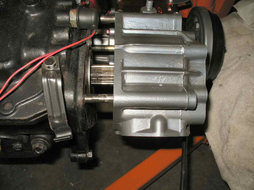
If you are going to use the floor shifter with the conversion then remove the entire mechanical shifter lever system and set it aside. See Fig. 4A.
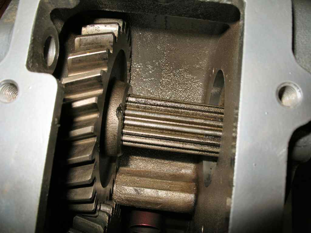
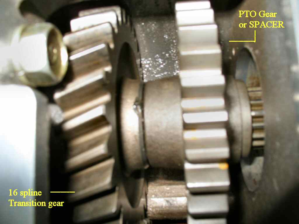
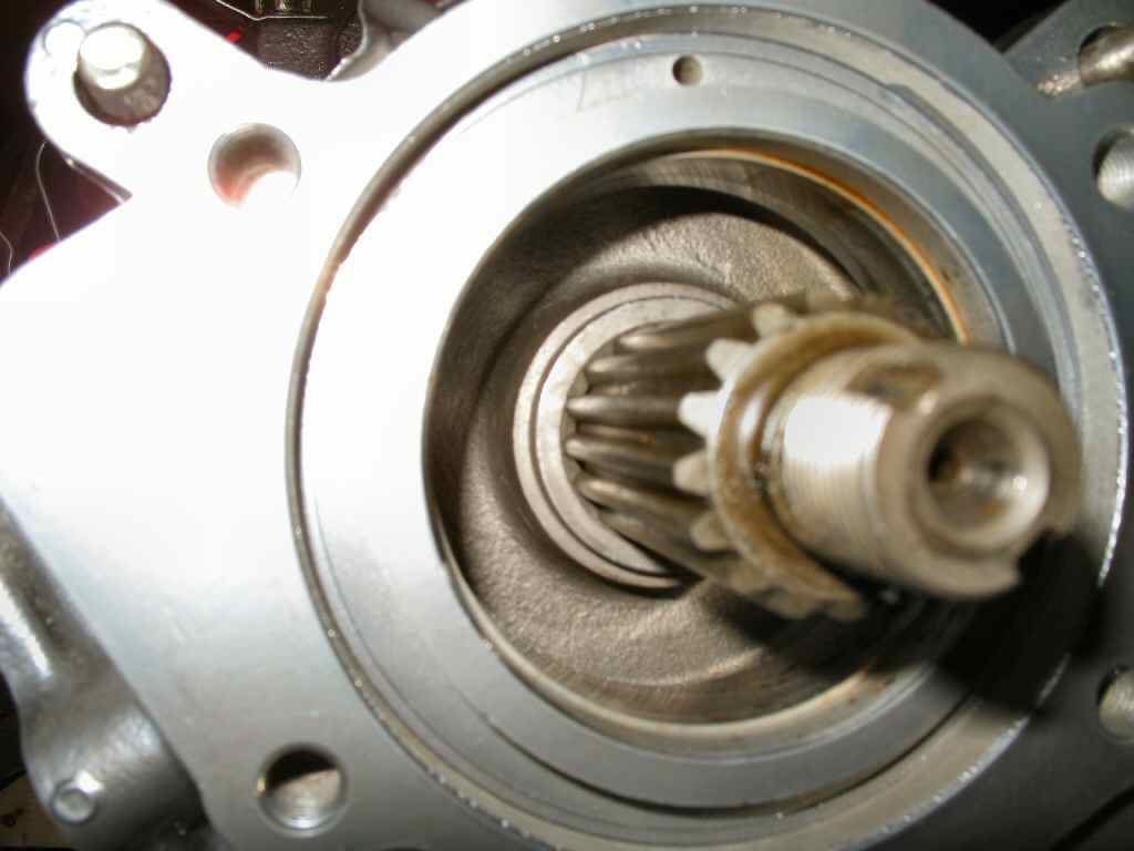
Fig. 5 Inspecting T-Case gears
|
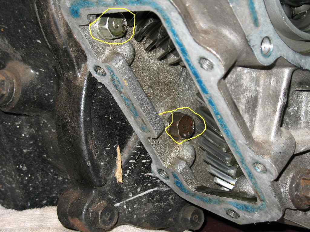
Fig. 6 Removing Output shaft nut |
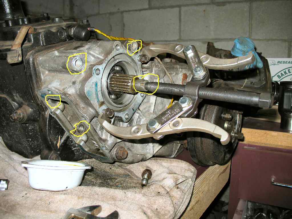
Fig. 7 Three Long Bolts |
Fig. 8 Two Short Bolts |
Fig. 9 Pulling Case |
First I removed the 4 speed T-Case PTO and output shaft covers. I was hoping to find a 4 speed PTO gear but no such luck. See Fig. 5.
Next I jammed a brass drift into the gears (See Fig. 6.) then used a large crescent wrench to remove the output shaft nut. Don't lose the spacer, washer and locknut from the shaft you will reuse these!
Locate the 5 bolts shown in Fig. 7-8 and remove them. You will use these bolts for the 3 speed case.
Now I used a large two jaw puller braced against two of the output cover bolts to remove the t-case from the transmission. Remember that the input gear and spacer will fall out so be sure to catch them or have a soft landing for them... Now I had a free 4 speed transmission!
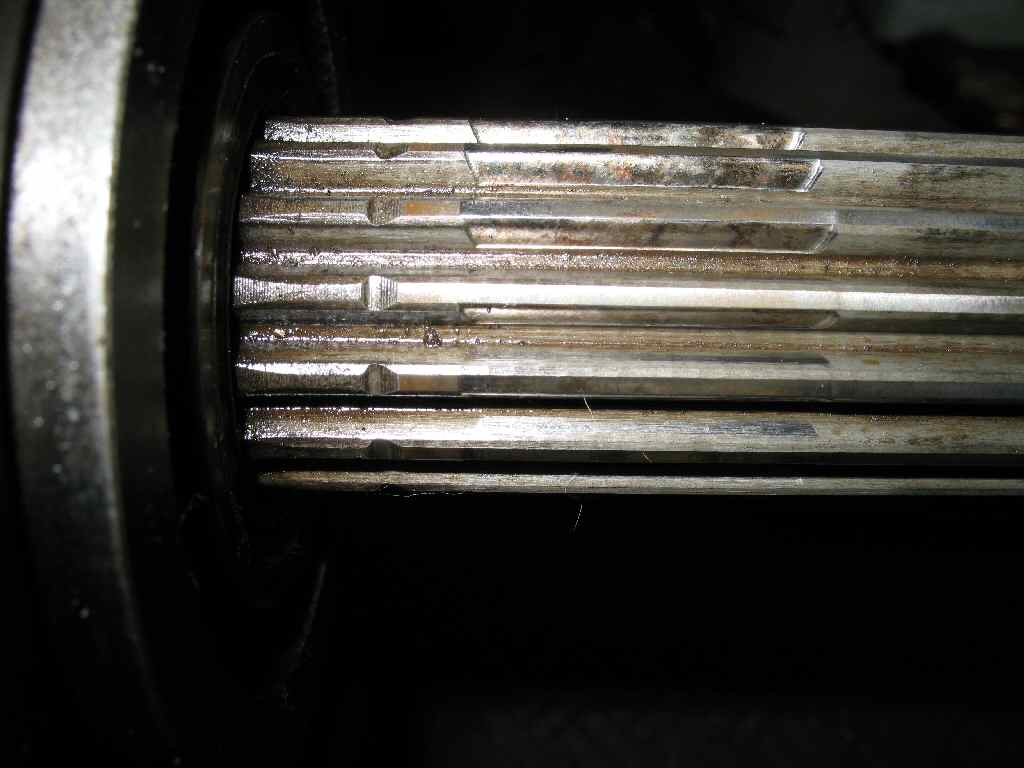
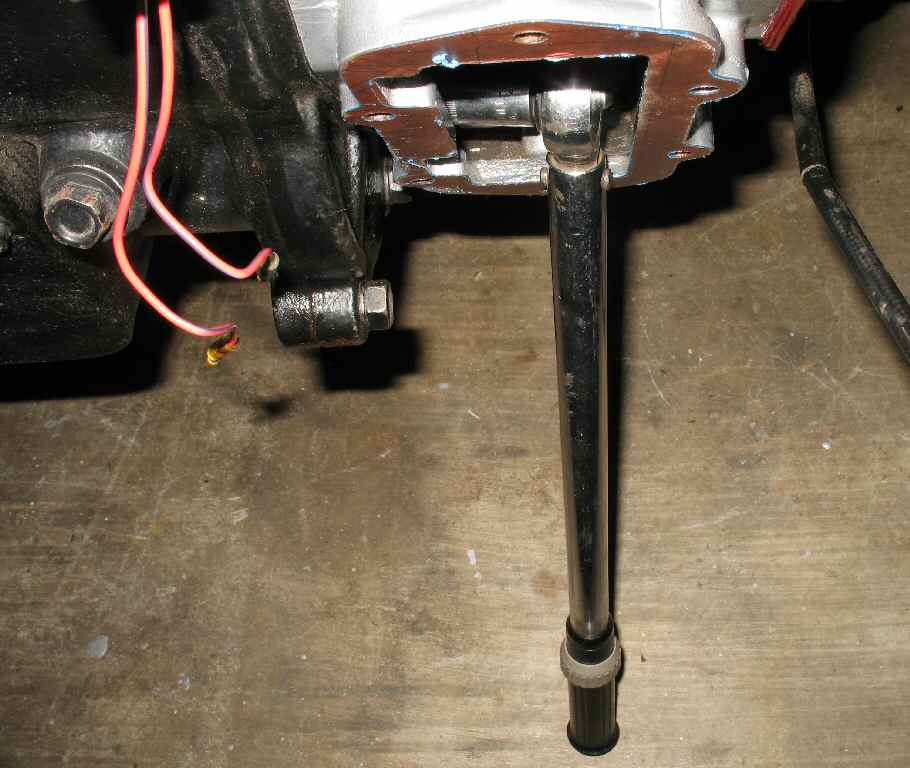
Fig. 10 Shaft Wear |
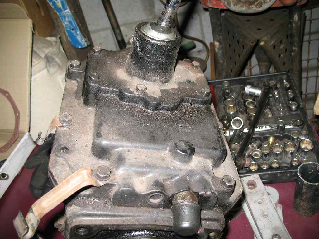
Fig. 11 Dirty Tranny |
Fig. 12 Ready to Install |
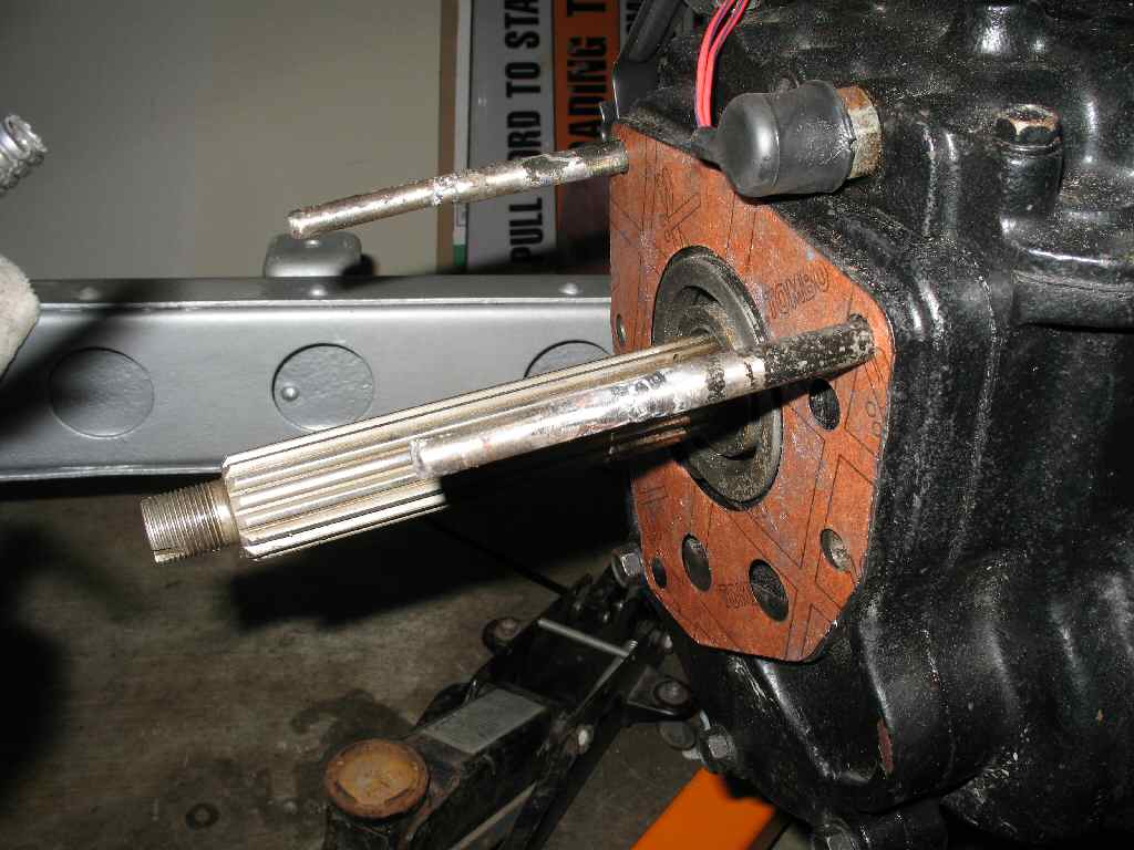
I started by inspecting the output shaft spline's for excessive wear. See Fig. 10. No one I showed the pics to seemed to think this amount of wear was excessive so I went with it!
I cleaned up the outside and top, which had a bit of dirt on them, (See Fig. 11) powder coated the cable holders and finally repaired the reverse switch harness and rubber cover. After cleaning the shafts I hung the tranny from my engine hoist and got ready to install the tranny onto the bell housing. See Fig. 12. See here for the 4 sp bell housing and 3 sp clutch/flywheel install.
Fig. 13 Sliding it in! |
Fig. 14 Another View |
Fig. 15 In Place |
Fig. 16 Hmmm... |
I read on IH8Mud about making some guide bolts to help the tranny align easier. I had some 5" bolts from a Nissan I parted out. I cut the heads off, chased the threads in the bell housing with a tap, then threaded the guide bolts into the bell housing. See Fig. 13-14.
Now I was ready to prep for the install. I lightly greased up the tranny input shaft then made sure the throw out bearing was positioned properly. The hoist made it easy to position and the guide bolts made alignment a non issue. I was expecting a struggle to get the shaft into the clutch but everything slide right in! I threaded in the lower two bolts then removed the guide bolts one at a time and replaced them with the tranny bolts. Oh yeah! See Fig. 15.
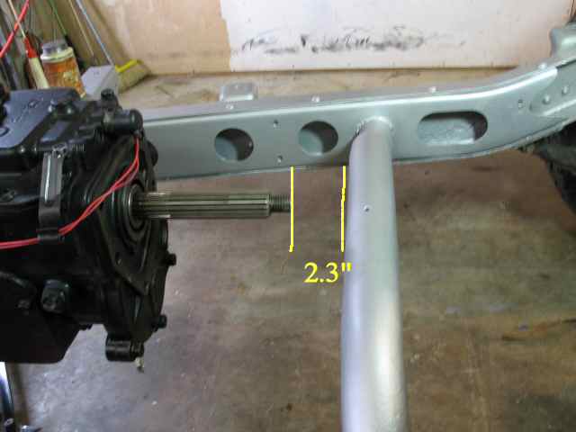
Well then I measured the clearance from the end of the output shaft to the cross member, about 2.3". Measure the thickness of the t-case and it was a bit over 5 inches. Grrr.... No way I can get the t-case on without lifting the engine. I posted a question to IH8MUD and sure enough the response was to just lift the engine up 1 foot, stab the t-case on and lower it back in place. So... that's what I did... I AGAIN hooked the engine up to the hoist and raised it up about a foot and turned it so I could have room to stab the t-case on.
Fig. 17 Ready to Install |
Fig. 18 Home made SST Guide Bolts |
Fig. 19 Sliding it on |
Fig. 20 Forget Something? :) |
I set the T-case on a board laid across the frame. See Fig. 17. I gathered all my tools, gaskets, gears and such needed to install and laid them close at hand.
I'll tell you right now, get help for the T-case install! I actually was able to do this by myself, but there was a LOT of cursing and frustration involved.
I started by making up some long guide bolts. I welded on some extensions to the tranny guide bolts used earlier when mounting the 4sp tranny. These bolts need to be at least 5" or longer. I threaded these into the top two tranny holes.
Next I applied a thin coat of Blue RTV to both sides of the t-case to tranny gasket, slide it over the guide bolts, and up against the tranny. See Fig. 18.
All excited now, I picked up the t-case, positioned it on the guide bolts and slide it on! Wow! That was EASY! Lets grab a beverage! Oh wait, what's that gear laying there? See Fig. 20. (Insert cursing here) Remember when I said get help for this? This is why. Trying to hold the transition and PTO gears in place with one hand, while supporting/manipulating the case with the other is a bit difficult... The guide bolts do make it a LOT easier though.
Fig. 21 Gears Installed |
Fig. 22 On! |
Fig. 23 Bolts |
Fig. 24 Torque the T-Case Down! |
Anyway I finally got the gears into the case. See Fig. 21. Note: If you are not going to have a PTO gear then you will need the spacer out of the 4 sp t-case or the one in the kit that Downy and others sell. It will replace the PTO gear and provide the proper clearances.
Once the gears are in place, make sure the t-case is all the way against the transmission. See Fig. 22. Thread the two short bolts that are inside the t-case into the tranny. See Fig. 8 above. Hand tighten only at this point! Now, one at a time, remove the guide bolts, and replace them with the proper bolts from the 4 sp t-case. Install the last long bolt. See Fig. 23 for the bolt locations. (Sorry that pic is out of sequence and shows all the covers installed!)
(At this time I put the engine back down on the motor mounts so I could torque stuff down. )
Now use your torque wrench and torque all 5 t-case to tranny bolts to 25-30 ft lbs. Use a cross pattern. See Fig. 24.
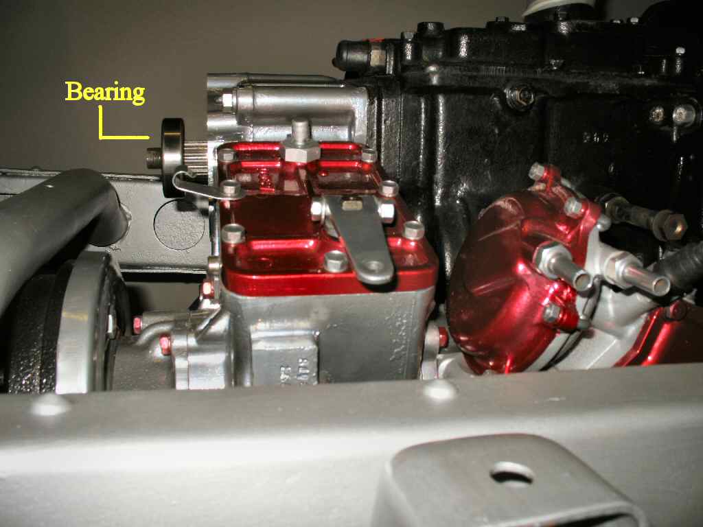
Fig. 25 Ready for the Bearing |
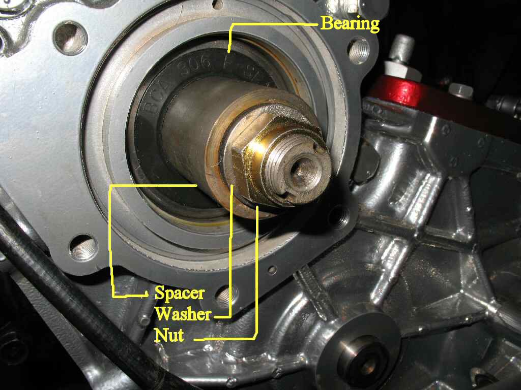
Fig. 26 Installing Bearing |
Fig. 27 Main Shaft Stuff |
Fig. 28 View 1 |
Fig. 29 View 2 |
Fig. 30 View 3 |
Locate the Datsun B210 rear wheel bearing and put in in the deep freeze for about an hour. This will make it a LOT easier to drive it onto the output shaft! Also, unless you have the SST, you will need to fabricate a bearing driver tool from some 2" metal pipe. Retrieve your frozen bearing, put some 90W on the outer and inner race, and start driving the bearing onto the output shaft. Drive it until it's fully seated in the t-case. Sorry no pic of this but you can see the bearing in Fig. 26. You can also see how close the E-Brake drum is to the cross member!
Now install the output shaft spacer/washer and lock nut as shown in Fig. 26. Use some red loctite on the nut. Jam something into the t-case gears as shown in Fig. 6 above, then torque the output shaft retaining nut to 101 - 108 ft lbs. Don't forget to stake the nut so the nut can't back off!
Now you can install covers on the T-case. Use some RTV on both sides of the gaskets and tighten the bolts down in a criss cross manner. Eye Candy in Fig. 28-30...
Hosted by Global Software, Inc.
©1998 - 2023 Mark C. Baker Web Designer
Please: No part of this web site may be used without express permission... email mbaker@globalsoftware-inc.com for permission.