At this time you will need to address rebuilding the mechanical
2WD/4WD shifter housing or the vacuum 2WD/4WD shifter housing. I performed
both rebuilds for your viewing pleasure though I am going to use the Vacuum
shifter as that what it left the factory with. There are links at the bottom
of each page to return you here.
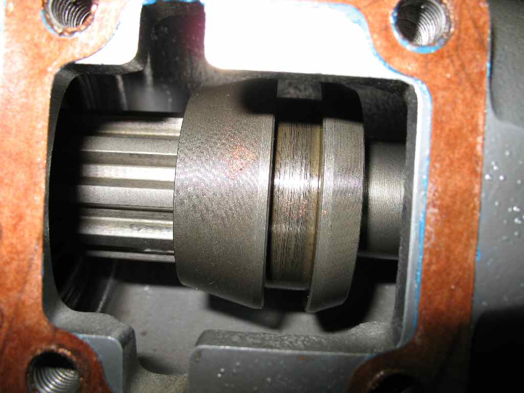
Ok, so which ever shifter you are going to use, find the
square extension housing gasket, coat it with a thin film of silicone , place
it on the housing, then position the clutch sleeve shown in Fig.
1 so that the shift fork will engage the clutch sleeve properly. Note
that on the Vacuum shifter you may have to position the shift fork by applying
vacuum to one port or the other. Just suck on it! :-)
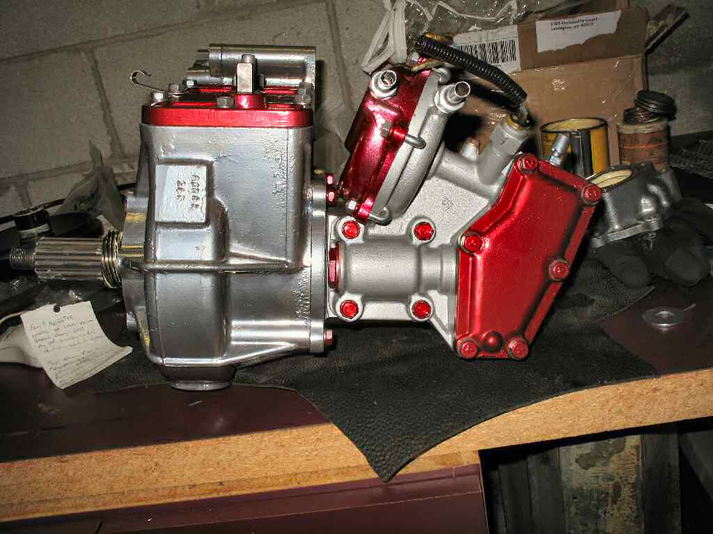
Insert the 4 8mm x 1.25 bolts and washers and tighten in
an alternating fashion. See Fig. 2 for the installed
shifter
Locate the 4Hi/4Lo Shift Lever and bolt for the top cover.
Install this and tighten the bolt. Note the shaft has a shallow divot machined
in it. The bolt sits in this divot. This keeps the lever up off the seal.
Assembling the E-Brake Backing Plate
Fig. 4
Fig. 5
Fig. 6
Fig. 7
Fig. 8
Fig. 9
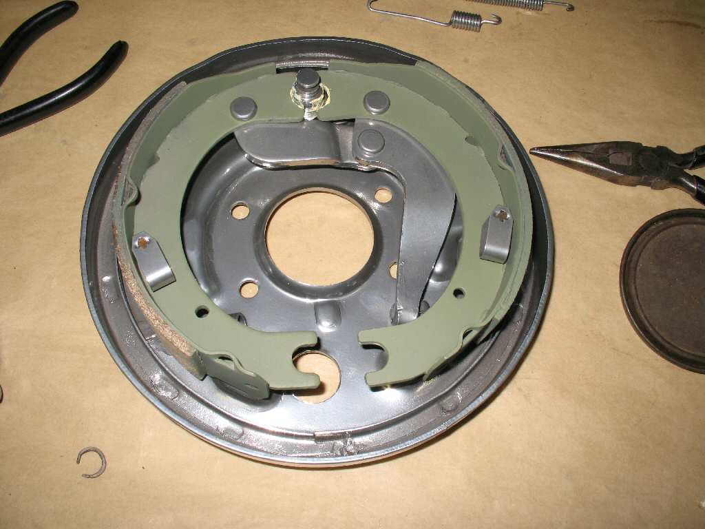
OK gather all the parts as shown in Fig.
4. You will also need some grease. Though the attached cable can be
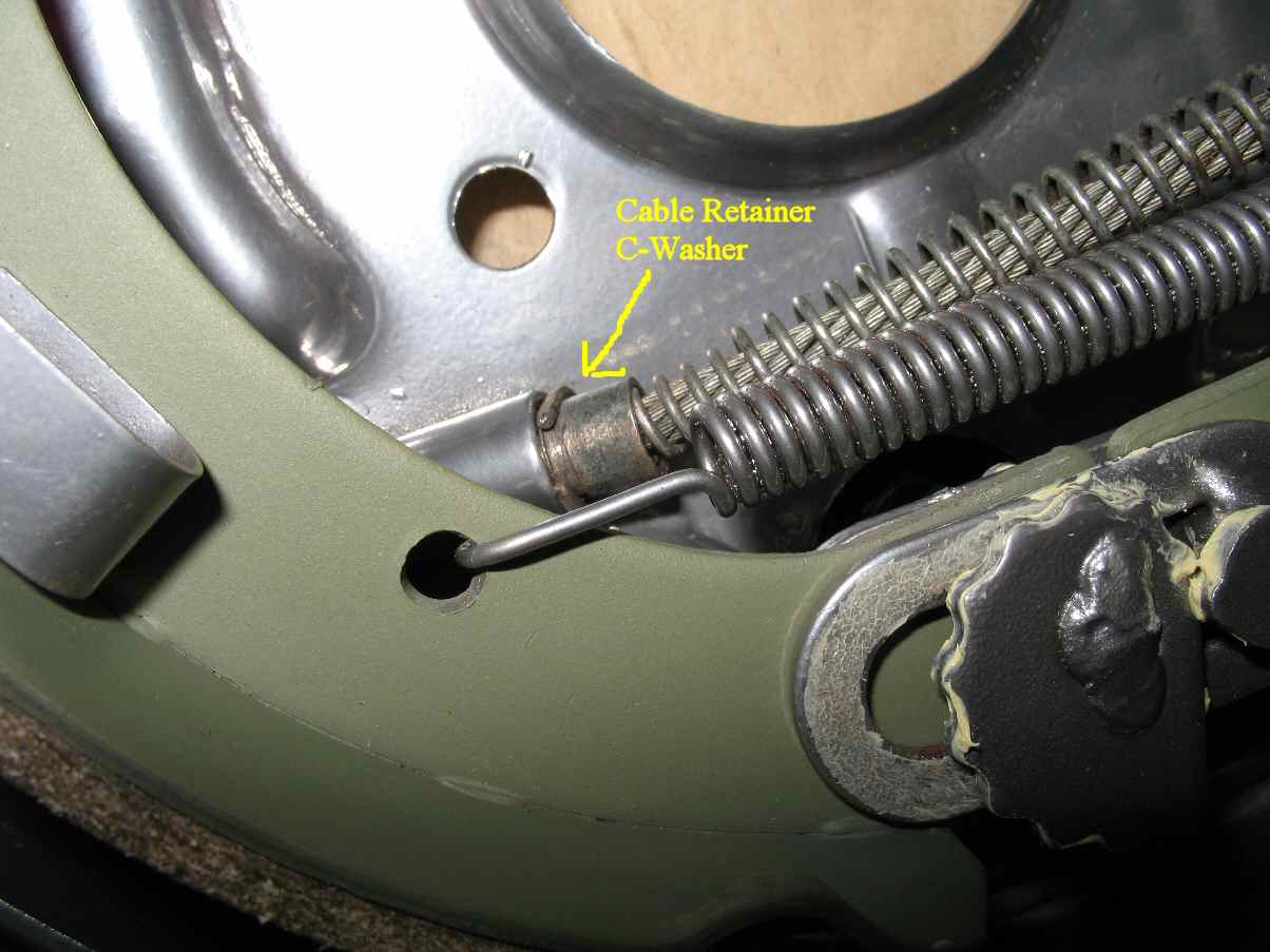
a pain, I highly suggest you connect the e-brake cable NOW. See Fig.
10 for where the retaining C-washer goes. You can do this after the
e-brake is all together as I did. It's just a lot more of a pain.
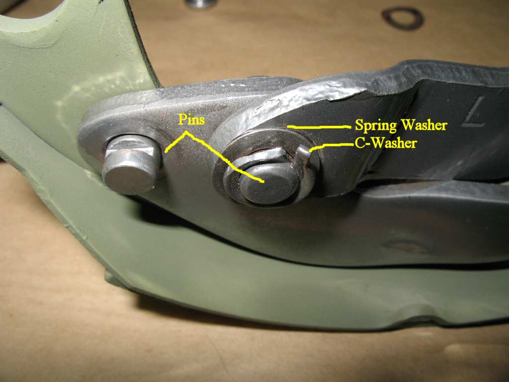
Start by assembling the shoe expander lever. The pins go
through the shoe then into the lever as shown in Fig.
5. Place a spring washer over the pin then place the C-washer in place
in the grooves and crimp it tight.
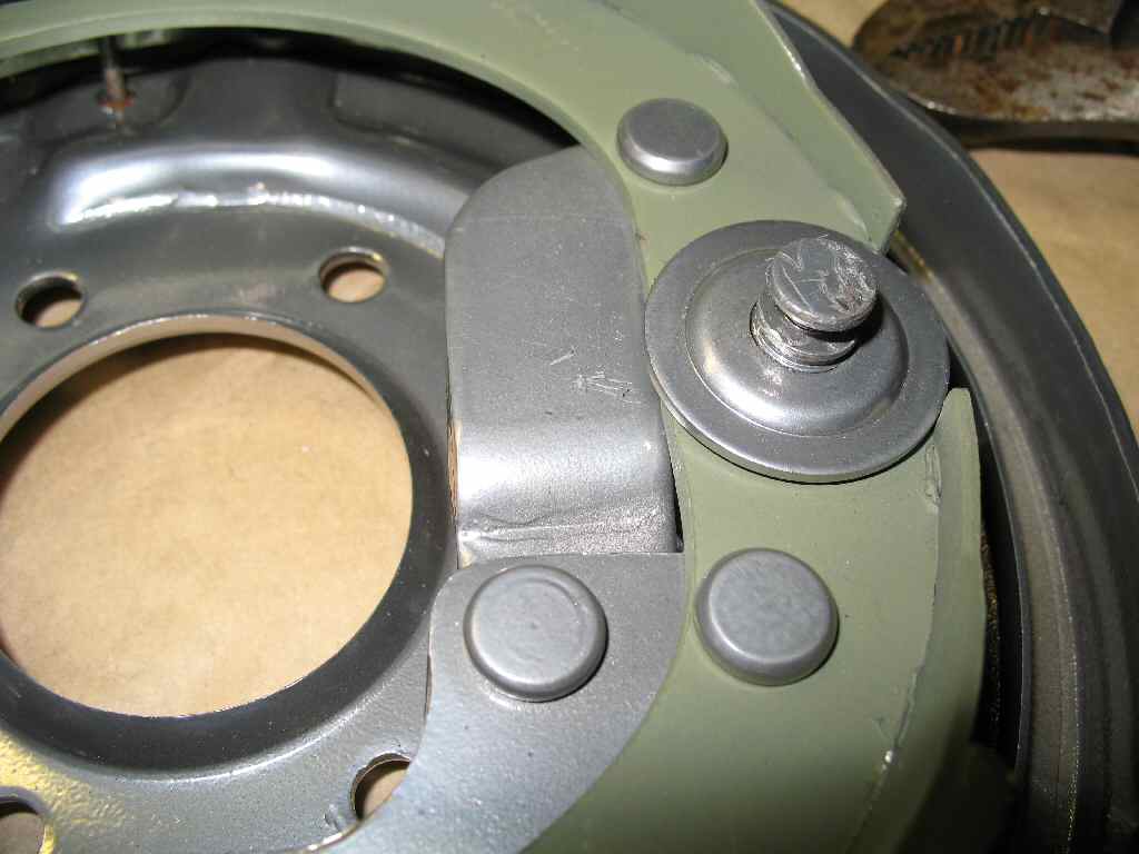
Place the assembly on the brake backing plate and insert
the shoe retainer pins through the back of the housing, through the shoe then
place a retaining clip over it. Compress the clip until the flattened head
of the pin comes through. Using a pair of needle nose pliers, grab the flattened
head and twist it 90 degrees to lock the clip in place. See Fig.
6.
Grease the ends of the shoes as shown in Fig.7.
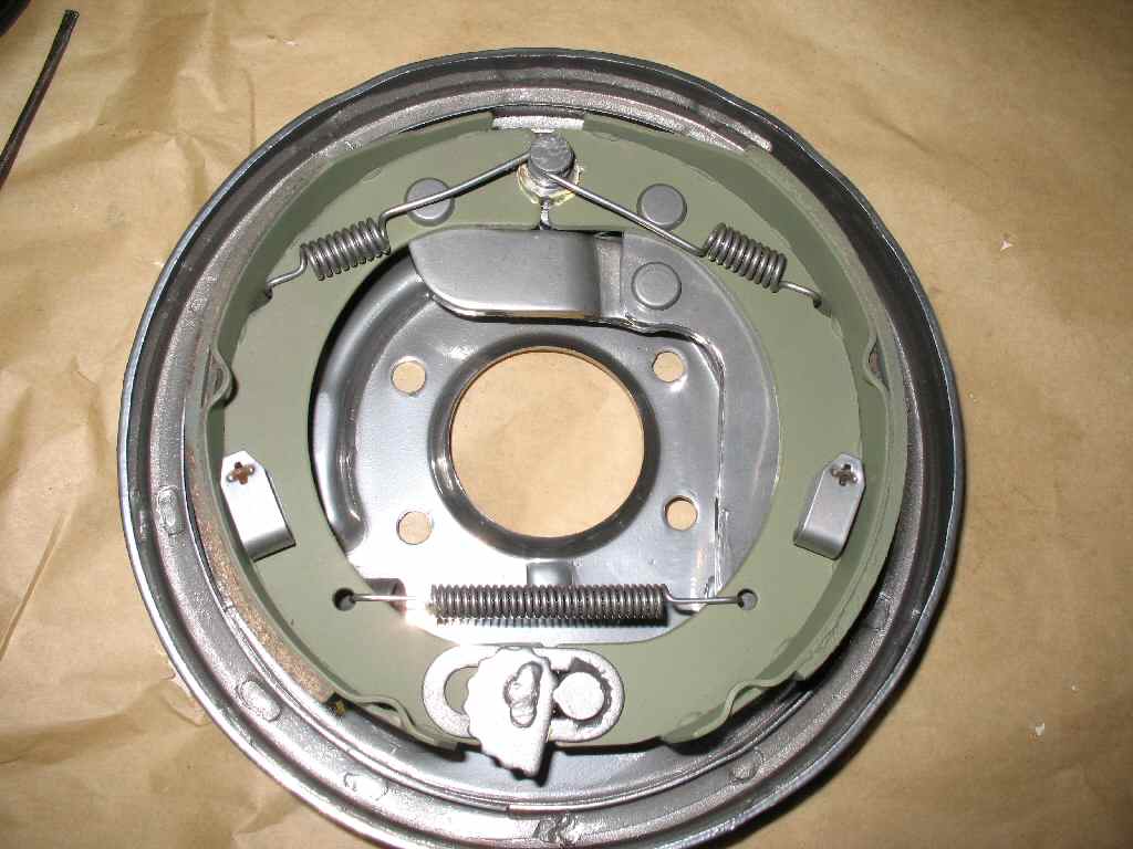
Grease the back of the stepped washer and place it over the pivot pin.
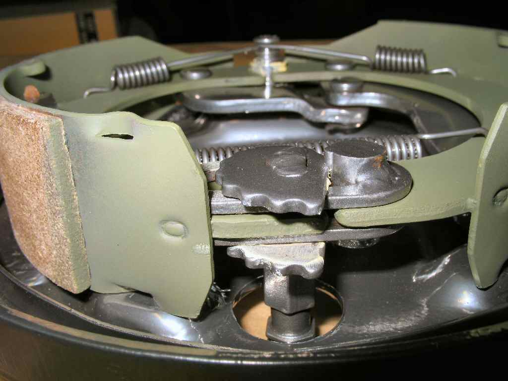
Attach the two top springs to the shoes and pivot pin. Refer
to Fig. 8-9, apply a small amount of grease to
the adjuster assembly and place it between the bottom shoes. Attach the bottom
spring.
Fig. 10
Fig. 11
Fig. 12
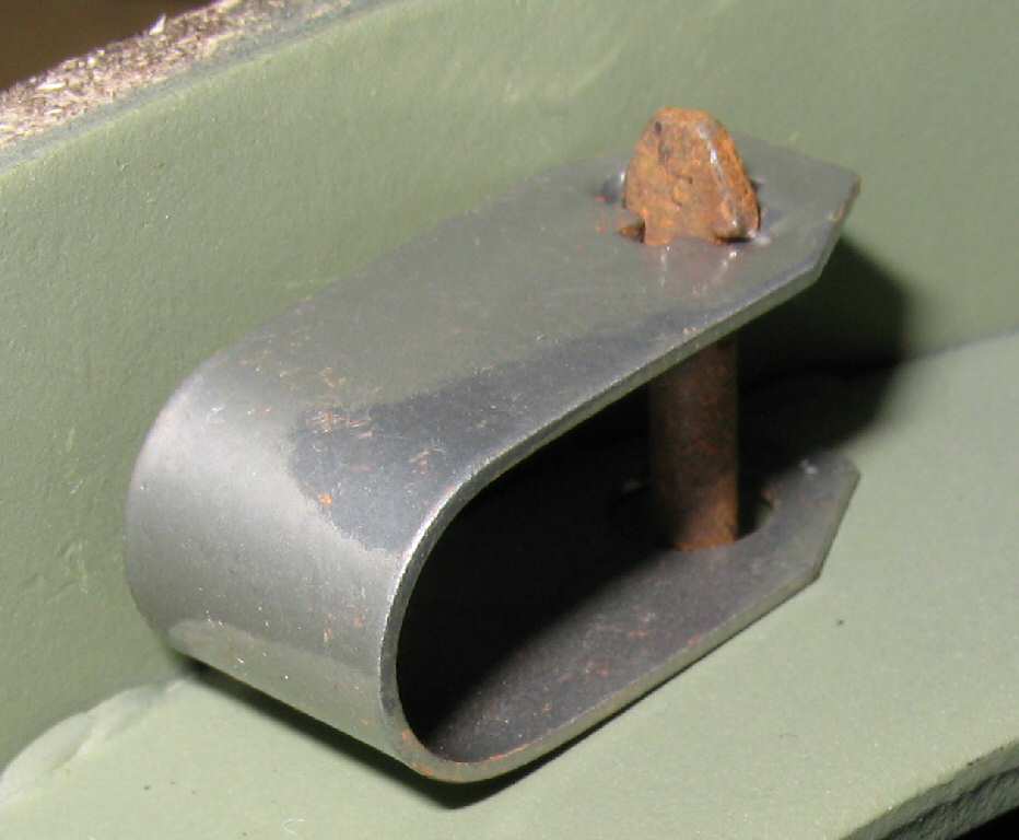
Fig. 10 shows where
the c-washer goes that hold the e-brake cable to the backing plate.
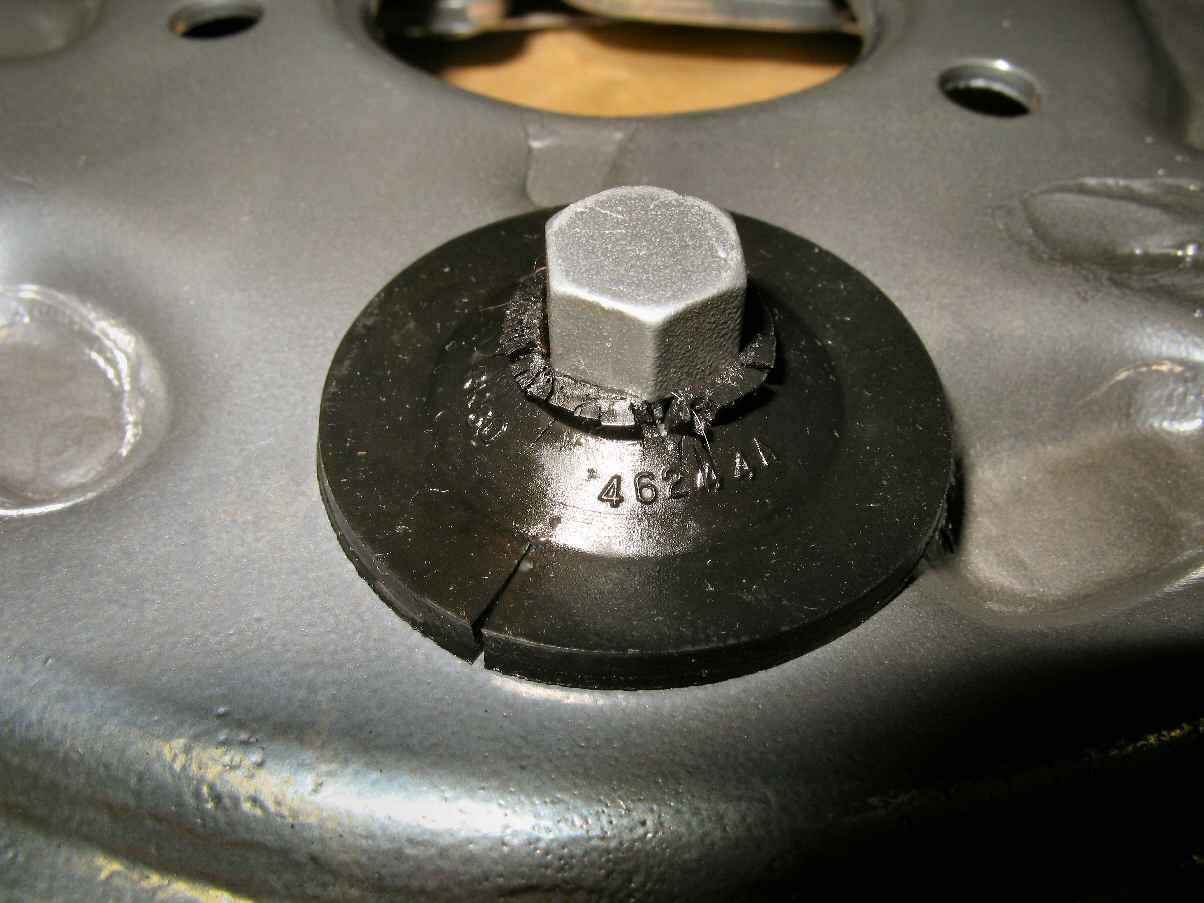
If you have one, place the rubber plug over the adjusting
stud to keep mud out of the parking brake assembly. See Fig.
11.
Just for reference purposes Fig. 12
shows the side view of the plug.
OK all assembled lets bolt it to the t-case. Get 4 8mm x
1.25 x bolts, apply some blue loctite to them, and attach the backing plate
to the speedo housing.