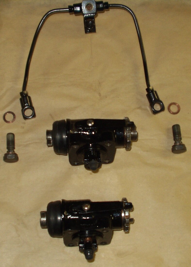
Gather the backing plate, two rebuilt
wheel cylinders, 8 mounting bolts with washers, hard line manifold with mounting
bolt, two hard line to wheel cylinder bolts (union bolts) with four new copper
washers, and a new set of brake shoes and return springs.
Fig. 1
Some of the parts
Ok you have 4 wheel cylinders, 2 with an
L cast in them and two with an R. The ones with an L are for the DRIVERS side,
the ones with the R the PASSENGER side. Separate them now! Work with one side
at a time to prevent mixing them!
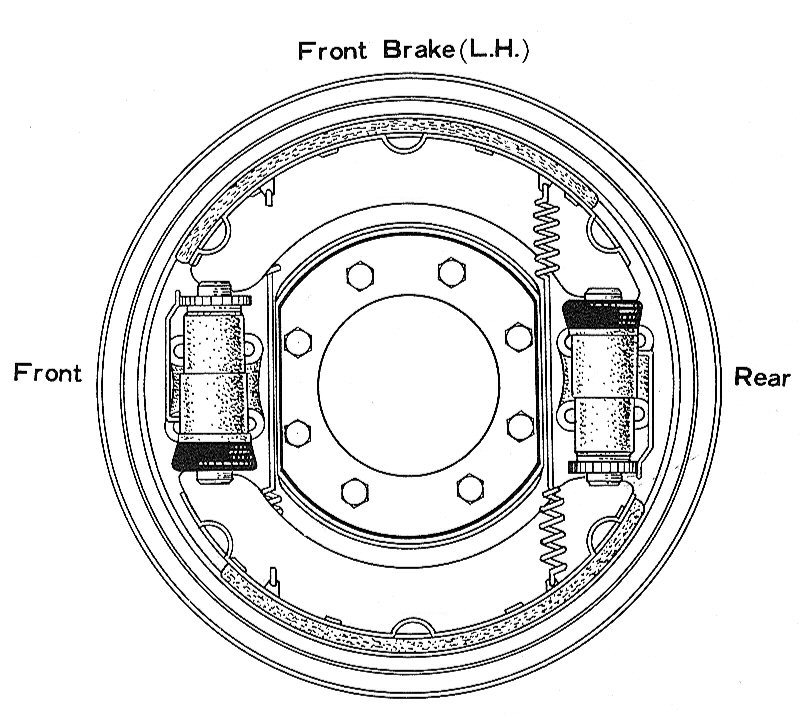
We will start with the Drivers side. Lay
the plate down so that the hard line mounting hole is up as in Fig.
2. Looking at Fig. 2 as a guide attach
the wheel cylinders with an L to the backing plate using 4 8mm x 1.25mm bolts
and lock washers. Pay attention to the orientation of the wheel cylinder brake
adjusters! The left one goes up the right one down.
Now attach the brake hard line manifold to the back of the
plate. Leave the mounting bolt loose.
Attach one end of the manifold union to a wheel cylinder.
You may have to bend the line to line it up, just don't kink it. Remember
one copper washer goes under the union bolt head the other goes between the
wheel cylinder and the manifold union! Leave the union bolt loose.
Attach the other line to the other wheel cylinder. Now go
back and FIRMLY tighten the 17mm union bolts. You are compressing the copper
washer to make a seal for the hydraulic fluid.
Tighten the manifold mounting bolt.
For attaching the shoes you either need a partner or you
can wait to do this once the plate is mounted to the spindle. I had a partner
so I went ahead and mounted the shoes. Lay the shoes out on the bench beside
the backing plate oriented as shown on Fig. 2
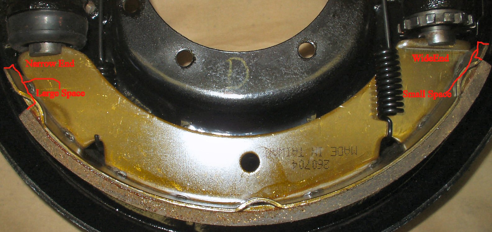
and Fig. 3. You'll notice that the mounting ends
of the shoes have a wide end and a narrow end. The wide end fits into the
adjuster and the narrow end goes into the piston. Also the lining as mounted
on the shoe is offset. The gap is largest on the piston side and smallest
on the adjuster side. Again see Fig. 3.
Fig. 2
Page from Manual
Fig. 3
Mounting Shoes Correctly
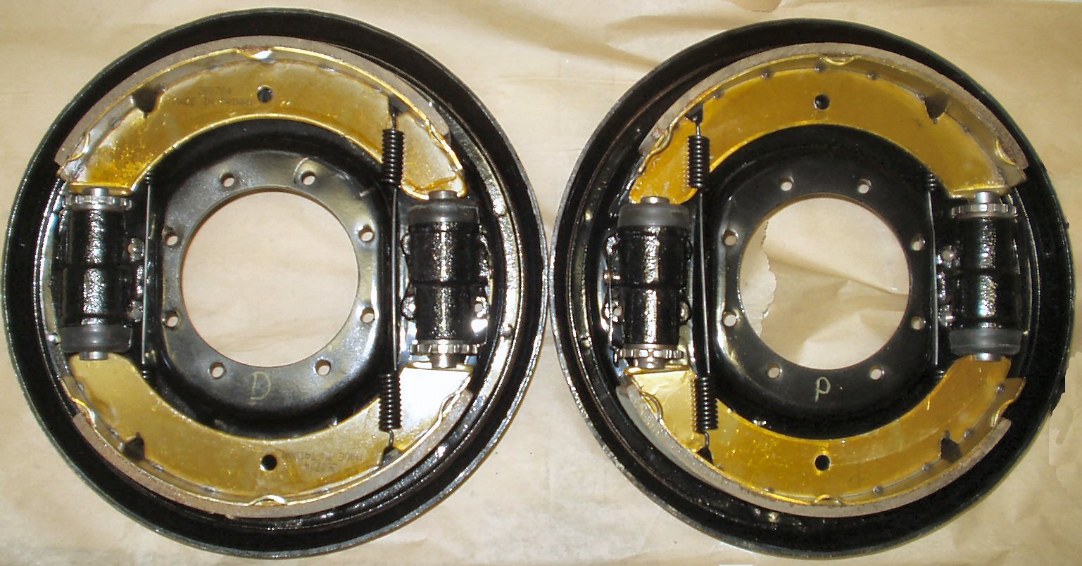
Fig. 4
Completed Set
Using Fig. 2-3
as a guide attach the brake return springs to the shoes. The left spring goes
BEHIND the shoes the right spring goes in FRONT of the shoes.
Get your partner. You grab one shoe and he grabs the other.
Keep the springs attached. Have the partner slide his shoes into the adjuster
and piston on his side.If your truck has the spring hold down pins and clips
then attach them now to that shoe to hold them in position. Now have him firmly
hold the plate while you stretch your springs and slide your shoe ends into
place. Attach the hold down pins and clips if you have them. Note: If you
are by yourself then wait until the backing plate is mounted on the spindle
so you can stretch them yourself.
Repeat for the passenger side. See
Fig. 4 for the completed set.