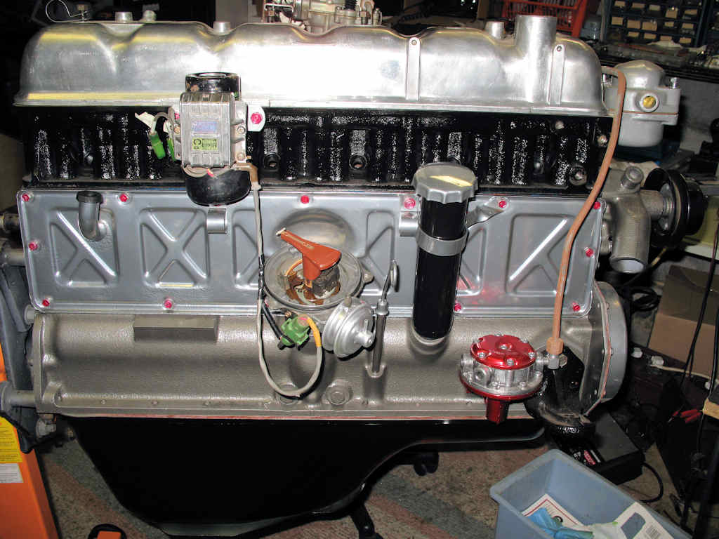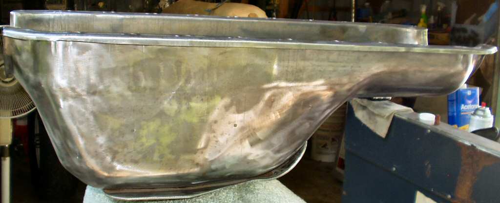
De-Rusted, wire wheeled
Fig. 1
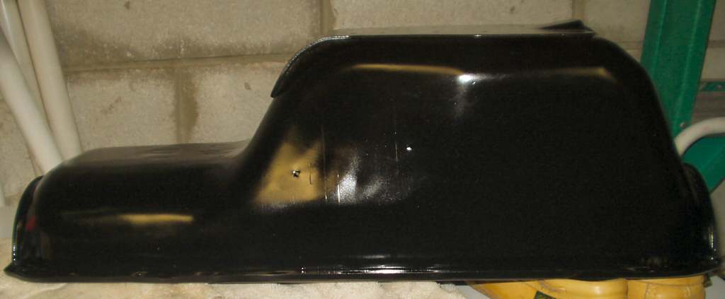
Black Enamel
Fig. 2
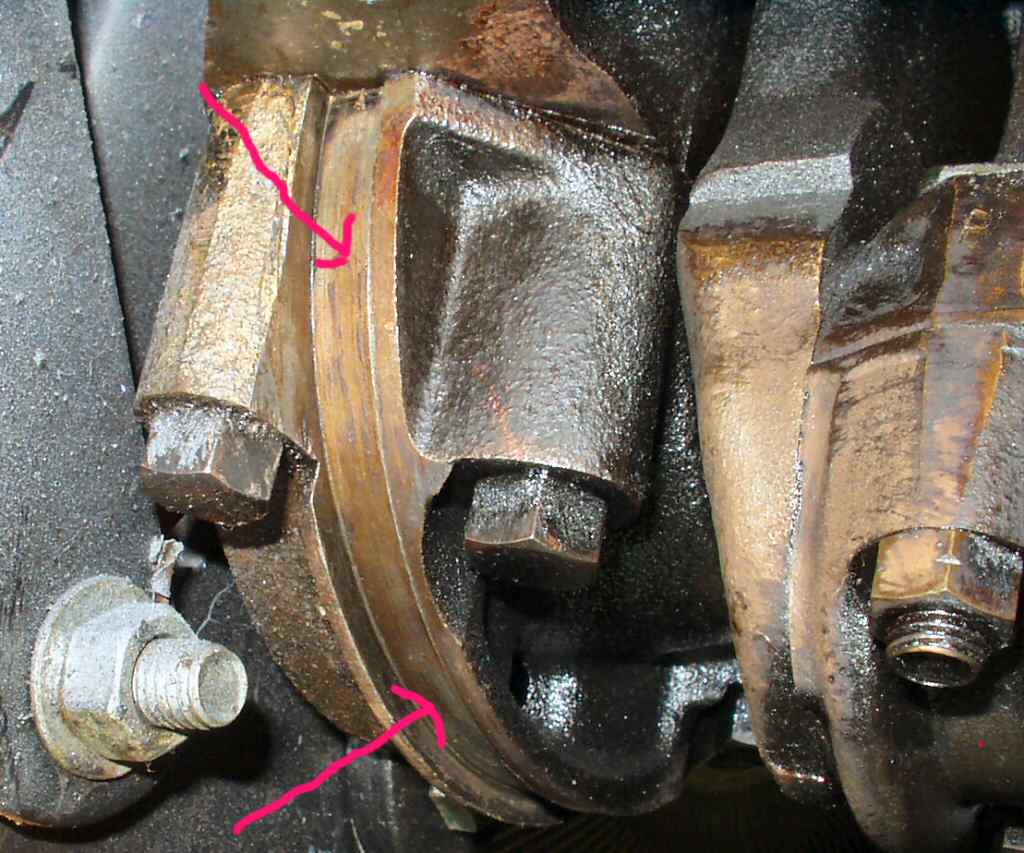
Crank to oil pan seal area
Fig. 3
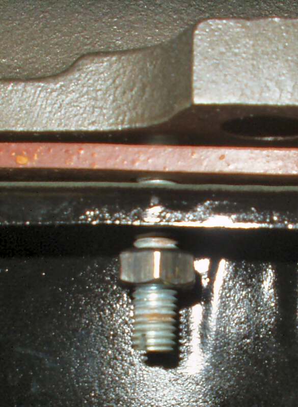
Temporary studs
Fig. 4
Now I can finally start putting it all back together! I started with cleaning up the oil pan. After degreasing in the parts cleaner tank I put it in the de-rust tank for a couple of days then ran a wire wheel over it. It was pitted a bit but not too bad. See Fig. 1. A coat of primer and two coats of black enamel and its ready to put back on. See Fig. 2.
De-Rusted, wire wheeled Fig. 1 |
Black Enamel Fig. 2 |
Crank to oil pan seal area Fig. 3 |
Temporary studs Fig. 4 |
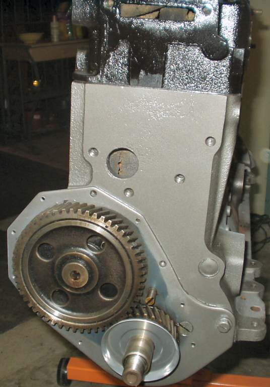
After cleaning off all the dust that had settled on the crank and such using a solvent soaked rag I wiped everything down with an oil soaked rag to get a coat of oil on everything. Following advice from Poser on IH8Mud I thoroughly cleaned the pan and engine block seal areas with acetone, coated both ends of the gasket where it meets the crank with a THIN layer of silicone, let it setup for 5 minutes, laid the gasket on the pan, and tied it at the four corners with small cotton string. Then I coated the area on the crank where the seal rides with a THIN layer of silicone (See Fig. 3) and while that was setting up threaded in 4 50mm long 8mm x 1.25 studs into each corner of the block. See Fig. 4.
The pan was raised onto the studs and 8mm x 1.25 nuts were threaded on just enough to hold the pan close to the block. Using a dental pick I could now move the gasket into place working side to side and inserting the oil pan bolts. Everything was left loose until the final bolt was in position then I removed the strings and studs from each corner and started a cross over pattern of tightening the bolts ending up at about 9 lbs of torque. (Please don't leak....)
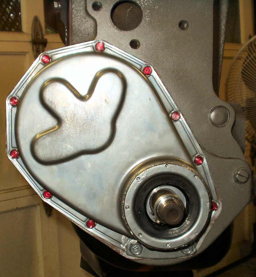
Next was the front timing cover. I powder coated the oil slinger just because I could and installed that. See Fig. 5. I also powder coated the timing cover and need to relate something about it. The crank seal is held in the cover by a separate 'cell' that's held in the cover by SOLDER! When I preheated the cover, the solder melted and dripped from the cover! I had to grind the solder out of the seal area to get it to seat. I'm betting that I will have an oil leak there once I get it running. Anyway I had ordered a new front seal which I installed, then got a wild hair to give the bolts a red anodized powder coat. Anyway see Fig. 6 for how it all turned out.
Fig.5 Oil Slinger |
Fig. 6 Will it leak? |
Fig. 7 Thermostat Housing |
Fig. 8 Powder Coating Parts |
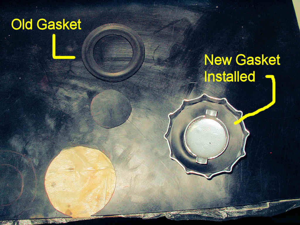
Fig. 9 Making an Oil Cap Gasket |
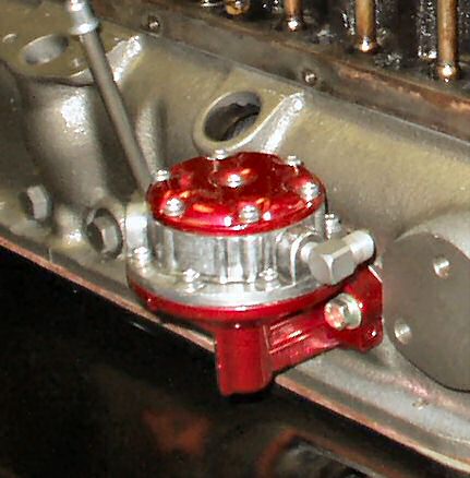
Fig. 10 Installed Fuel Pump |
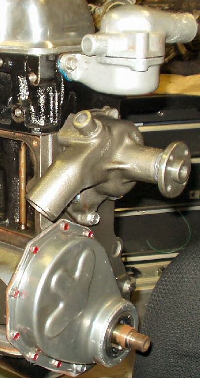
Since you can't powder coat the water pump unless you remove the big bearing, I just primed it and painted it same color as the block. See Fig. 7. I installed the thermostat that came out of the original as it is still good.
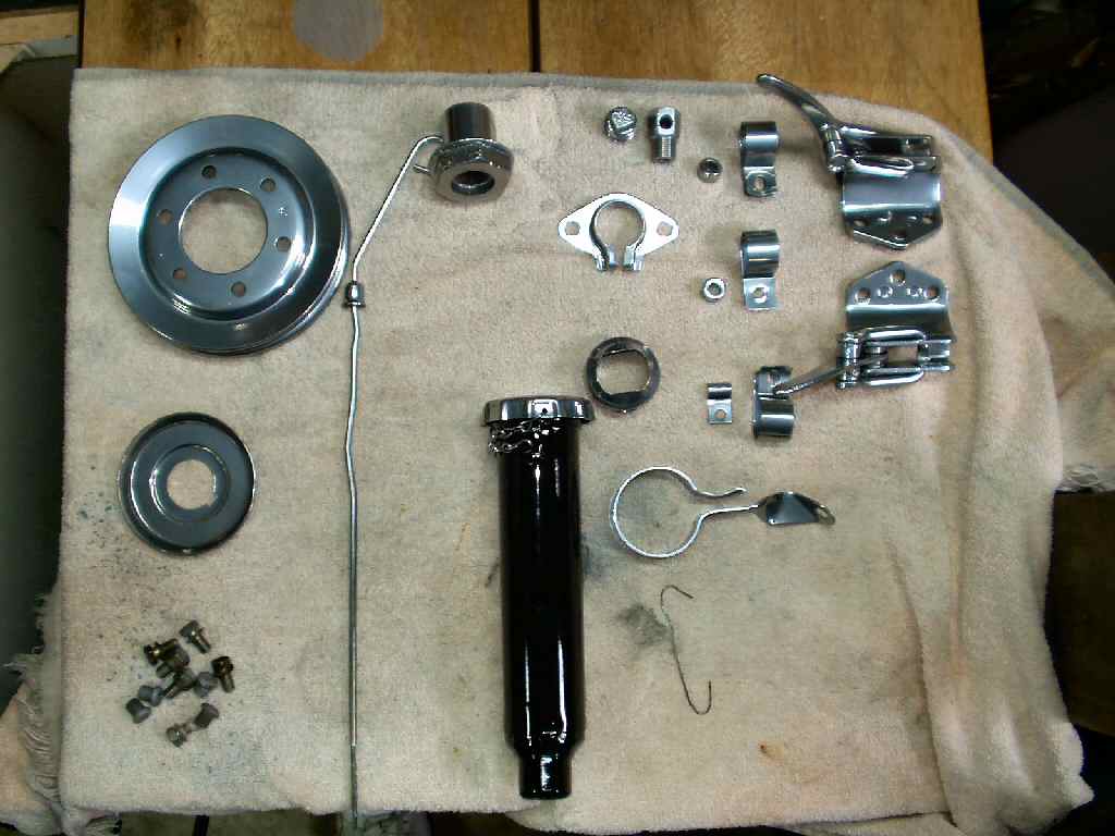
I powder coated the oil fill tube gloss black, the tube cap and oil dip stick extreme chrome. See Fig. 8. The rubber gasket for the cap was a bit worn so I made a new one. I used a compass to lay it out then scissors to cut it out. It came out great! See Fig. 9.
Next I installed the Fuel Pump that I restored. See here for that process. I made my own gasket, coated both sides with a thin coat of blue silicone and bolted it up. See Fig. 10.
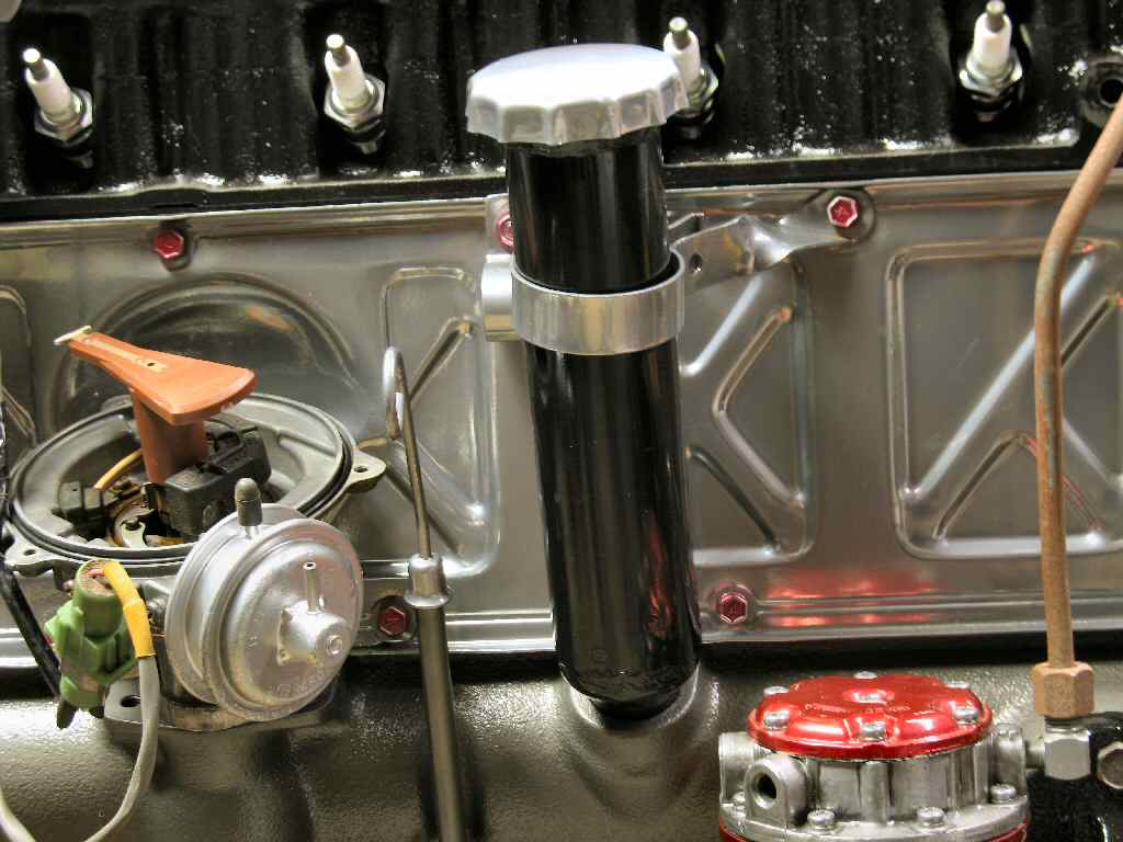
Fig. 12 Oil Filler Tube |
Fig. 13 Heater Hose Clamps |
Fig. 14 Passenger Side Getting Done! |
The engine side cover was powder coated in Extreme Chrome. It barely fit in the oven! I had it painted flat black but it was just too dark. I did the same anodized bolt treatment as the timing cover. I also made sure the bolt holes in the cover were flat by placing it on the anvil and used a body hammer to flatten out the dimples where the PO had over tightened them.
Note: This is a FJ60 side cover with the large 'dent' in it. In order to install it I had to make a couple of mods to it. First I had to cut some clearance in the metal housing that collects the combustion vapors to route to the PCV. Next I had to bend the copper tube that carries oil to the rocker assembly inward a bit as the dent was hitting it. Make sure to get a gap so there will be no rubbing on the push rod which could cause a hole in the line! Finally I coated both sides of the cork gasket with a film of silicone and tried to bolt it down... Hmmm... Gasket not lining up at all? Long story short, you will need to use something like a dental pick to align the holes and stretch the gasket to fit. Start at the top and get all those lined up, then down the sides, and finally across the bottom. Do NOT tighten anything down yet!!! When you have ALL the bolts in place then using a criss/cross pattern start tightening the bolts. Do NOT tighten down all at once! Make a couple of passes tightening a little at a time. Be VERY careful not to over tighten these bolts! You will dimple the cover and it WILL leak...
I temporarily installed the recurved FJ60 dizzy I just got back from Jim C. to get the practice. It slide right in and I love the one bolt mount/adjuster! See Fig. 11. Later it will be pulled so I can prime the oil pump.
Installing the oil tube back in the block was not as hard as I thought it would be. I was concerned that the powder coating would make the fit too tight but it actually will help seal the opening! I used a rubber mallet to start tapping it in, and though it was tight, it finally went all the way down. Attached the stabilizing bracket to a bolt on the side cover and all was good. See Fig. 12.
Next I installed the FJ60 Igniter and coil. It bolts into the same place on the head where my old F stuff was. Man I love a clean install! Just one wire to +12V and that's it! Here is a complete write up of the dizzy.
If you are planning on running a heater then you need to find the heater hose clamps, two longer bolts, and the clamp spacers. Install these as shown in Fig. 13.
Fig. 14 shows the finished work on the passenger side.
Hosted by Global Software, Inc.
©1998 - 2023 Mark C. Baker Web Designer
Please: No part of this web site may be used without express permission... email mbaker@globalsoftware-inc.com for permission.