Fig. 1
Removing the Locking Hub Face
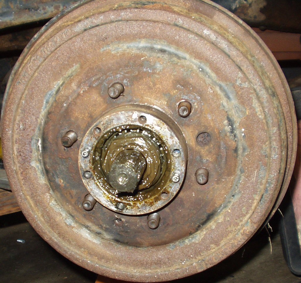
Fig. 2
Removing the Axle Snap Ring and Hub Body
Sooner or later every Cruiser owner will face what at first appears to be a very difficult task: Rebuilding the front knuckles. In fact this job is very easy! I consider it a one banana job but be warned it is VERY messy.
Before doing anything order the knuckle rebuild kit and brake kits for you vehicle. Several companies carry these kits. Have the parts ready to go so you don't have the truck in pieces waiting on the UPS man!
When I started this job I recalled how bad my brother always said the brakes were on this truck. I found out one of the reasons why below!
Tools |
Description/Job |
Snap Ring Pliers |
For removing the snap ring at end of axle |
Tie Rod Separator |
Beg. buy. borrow. steal. or rent this tool! (Unless you are replacing the tie rod ends then just beat them out.) The best tool is the one that presses them out. A pickle fork will of course work but will damage the boots. Get a set of boots if you use a pickle tool! |
Flat ended Brass Drift or Punch |
To persuade the cone washers to come loose and to knock the lower knuckle bearings out. Also to knock the knuckle bearing and wheel bearing races out. |
BFH |
To be used with the drift or punch for the above job plus for removing the tie rod ends and to beat on whatever is handy when neither will come loose! I use a long handled 3 lb sledge. |
17 mm 6 point socket |
For the steering arm and lower knuckle bearing retainer nuts and the tie rod end castle nuts. |
14 mm 6 point socket |
For removing the banjo connector bolt for the brake manifold |
10mm 6 point socket |
For removing the 8 small bolts holding the ball seals on the back of the knuckle. |
12 mm 6 point socket |
To remove the brake line manifold from the brake backing plate and to remove the wheel cylinders from the backing plate. |
17mm and 10mm flare nut wrenches |
For taking the rubber front brake lines loose from the hard lines, removing the brake manifold lines from the wheel cylinders, and removing the bleeder screws. |
17 mm open end wrench |
For Knuckle stud removal. |
52 mm 6 point socket (or a 2 1/16") |
To remove but most importantly to properly torque during installation the wheel bearing retaining nuts. |
Lug nut wrench or 22mm 6 point socket |
To get the wheels off. |
Large Phillips Screwdriver or impact
driver |
To remove the brake hub retaining screws if you still have them. |
Small pick or straight screwdriver |
For digging the lock washers buried in grease from the axle stub. |
Small putty knife |
For grease/dirt removal before and during disassembly and to get the rear ball seal retaining rings loose. |
Needle nose pliers or
cotter pin removing tool |
To get the steering arm tie rod end cotter pins out. |
2 Rolls of heavy duty shop towels |
To wipe off all the grease that will get on EVERYTHING ... |
2 pieces of 2' x 2' cardboard or old
wrapping paper |
Before starting lay this on the floor under each knuckle. As you clean and disassemble the dirt and grease falls on the card board. When done roll it up and throw away. For the more adventuresome stand it up and light it. It makes a hell of a torch when the grease catches ... |
Box of Disposable Latex Gloves |
Unless you like the feel of grease on your hands? |
Parts Cleaner |
Not totally necessary but sure makes it easier to clean all the parts. A large 5 gallon bucket about 1/3 full of kerosene works well also. |
Small boxes or baggies and a permanent
marker |
Use to keep parts separate and sorted. |
Safety Glasses |
When pounding on stuff with the BFH things tend to fly. |
Shop manual for your truck |
Several of these manuals are on line for download. www.birfield.com |
Tap and die set |
For cleaning up the threads on bolts and tapped holes. Note most sets don't include a 12mm x 1.25 (fine thread) die. This is what the tops stud threads are |
Start this job by chocking the rear wheels, placing the front axle securely on jack stands, removing the wheels and then thoroughly scraping off as much of the crud that has accumulated on the knuckle housings as possible. Now dump all the crud off the cardboard/wrapping paper you laid down and put it back in position.
Work on one side at a time from start to finish. You do NOT want to accidentally get parts interchanged side to side! Especially bearings! Be safe when you work, use your safety glasses, gloves and if you drink, don't drink so much that you mess something up! :-) Ok lets get started ...
Note: All pics are of the drivers side ..
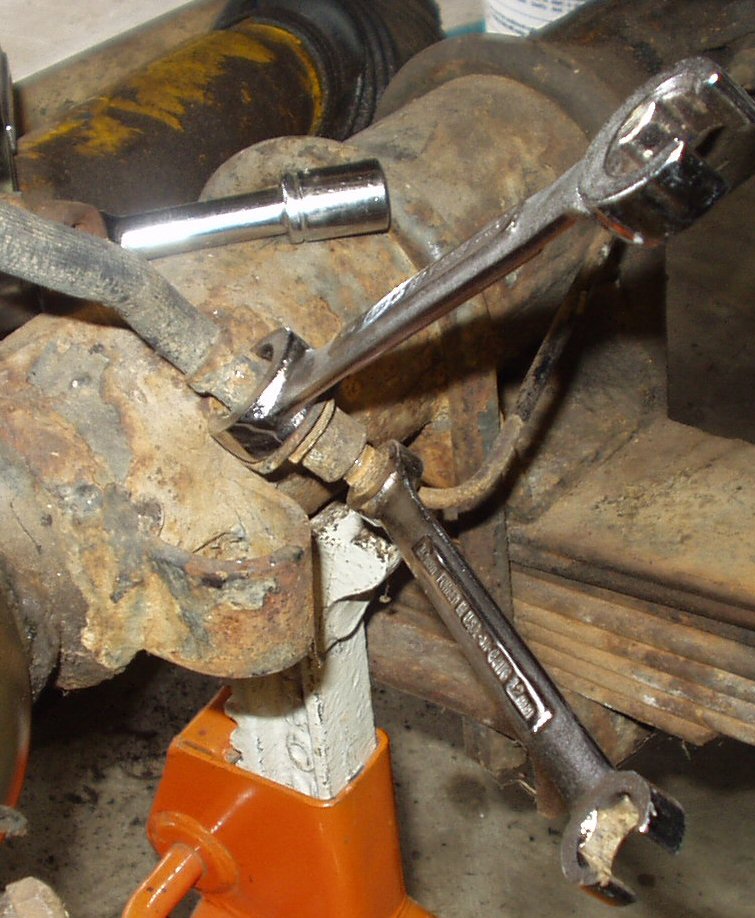
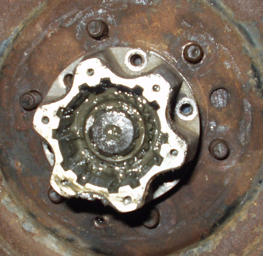
Fig. 1 Removing the Locking Hub Face |
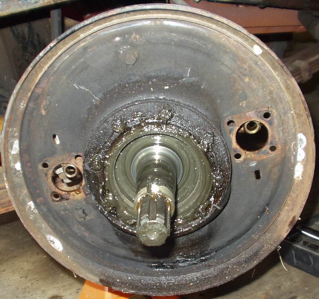
Fig. 2 Removing the Axle Snap Ring and Hub Body |
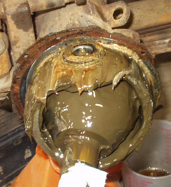
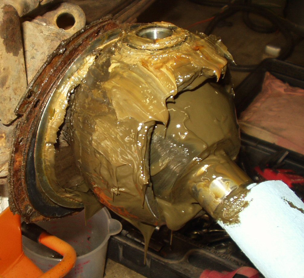
If you vehicle has them make sure the locking hubs are unlocked. Now using a 6 mm allen wrench remove the 6 allen bolts from the hub face. Carefully pull the hub face off and set aside to be degreased. If your axle seal has been leaking you will have a mess like what you see above. Use a paper towel to wipe the grease out so you can see the axle snap ring. Using your snap ring pliers remove the snap ring from the end of the axle. Now remove the 6 12 mm bolts holding the hub body to the spindle working back and forth just like you take lug nuts off. Pull the hub body off and set aside to clean.
Fig. 3 |
Fig. 4 |
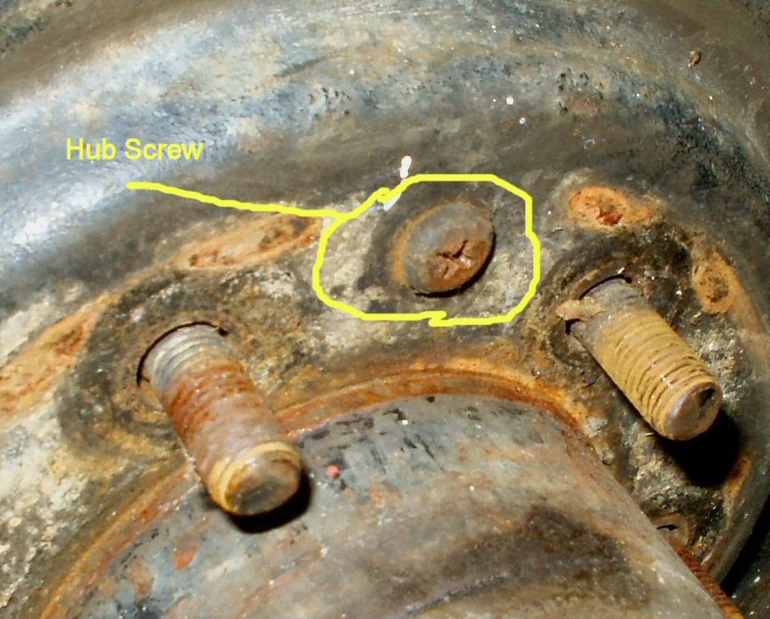
Removing the set screws and Drum Off
Remove the two set screws that hold the drum on if yours still has them. I would highly recommend using the impact driver to remove them if it's been awhile! Next try to slide the drum off the hub. If you feel the brake shoes dragging then use a screwdriver or a brake adjusting tool inserted through the backing plate and alternating back and forth between the wheel cylinders turn the adjusters in to loosen the shoes. Remember for the Driver Side the cylinder facing front needs to be turned counter clockwise and the one facing rear clockwise. For the Passenger Side the front facing cylinder needs to be turned clockwise and the one facing rear is turned counter clockwise. Remove the drum and set aside to be degreased and if need be turned.
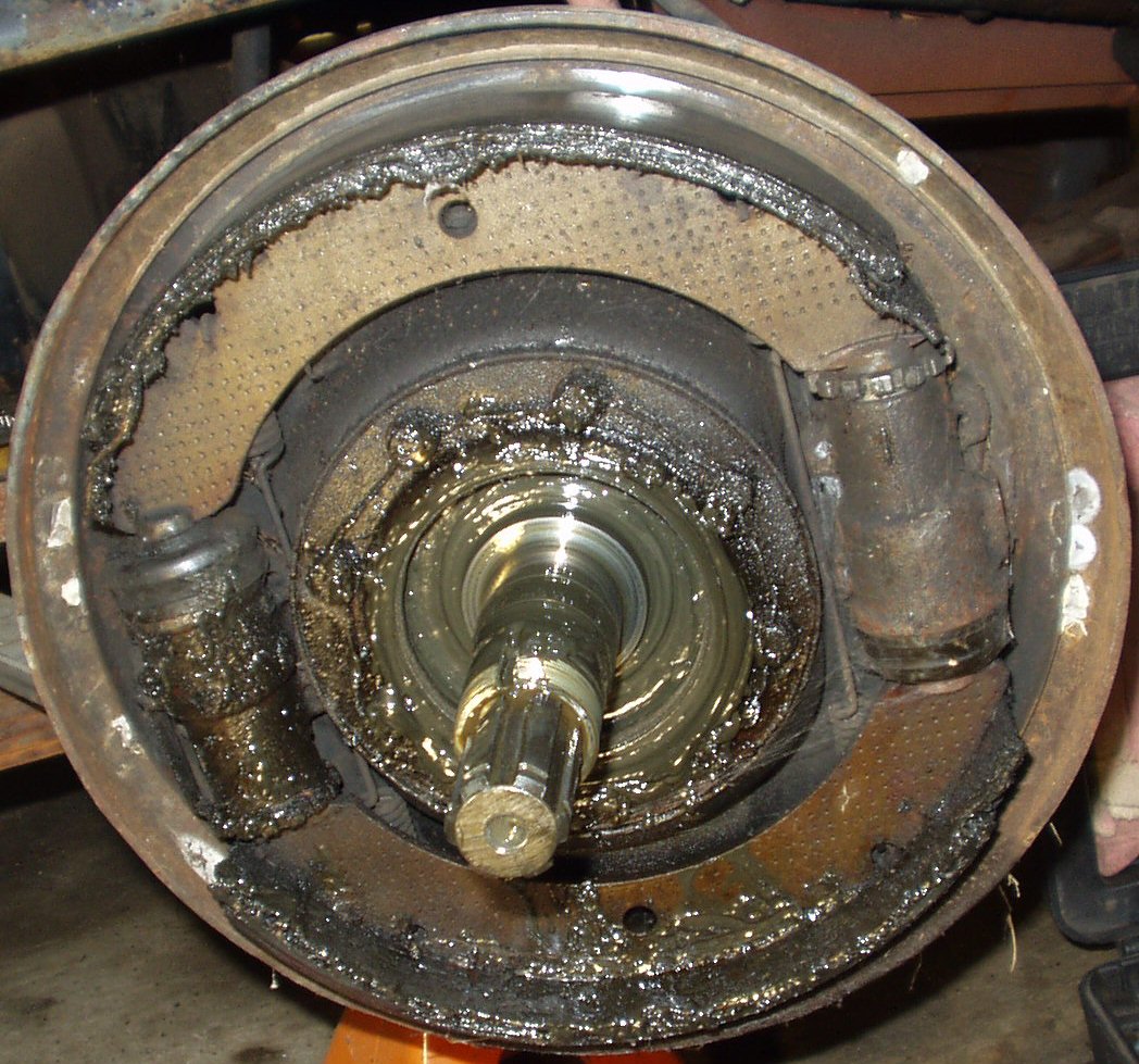
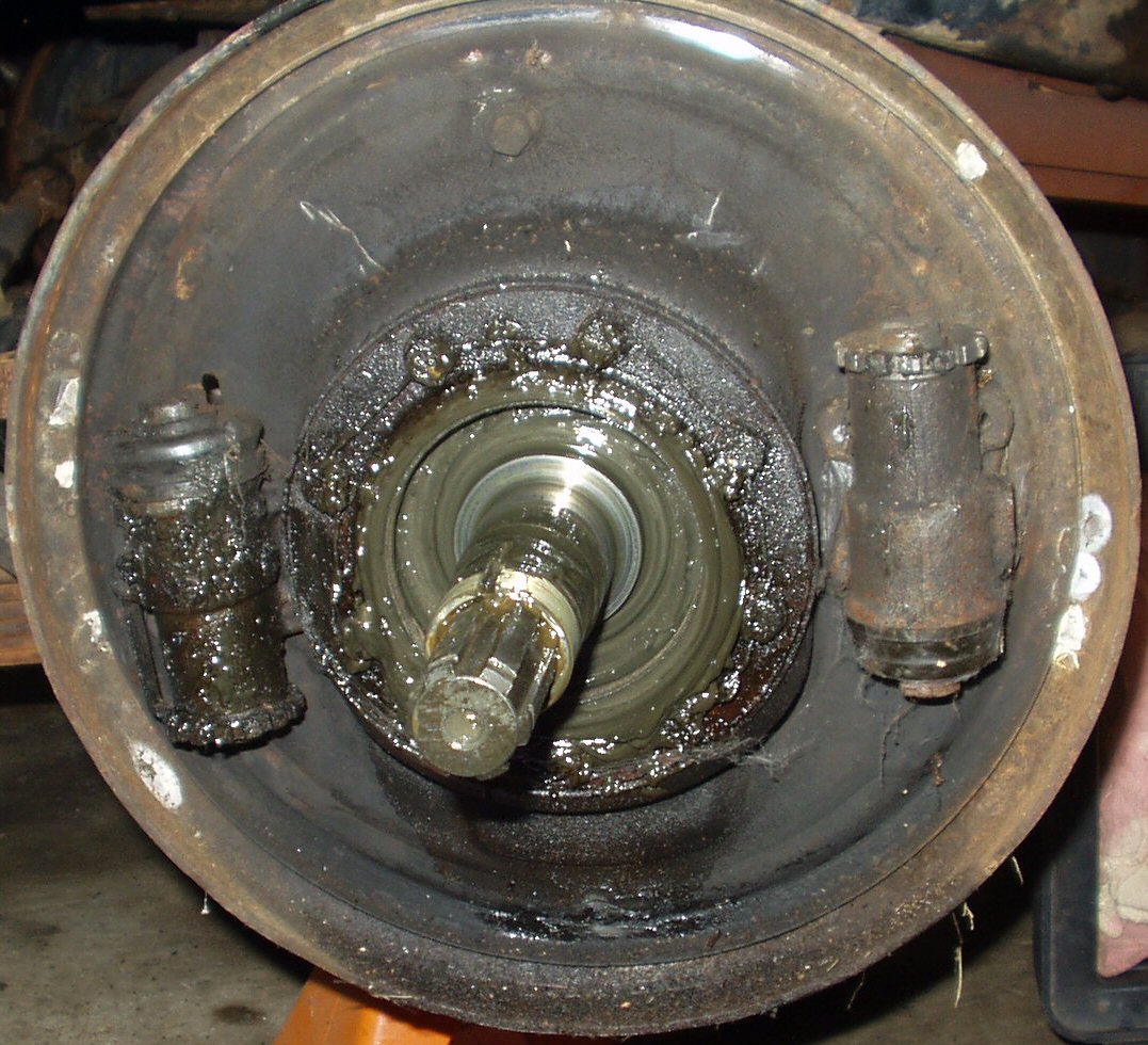
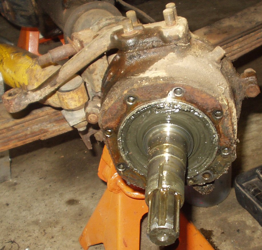
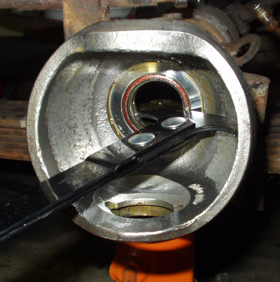
Fig. 5
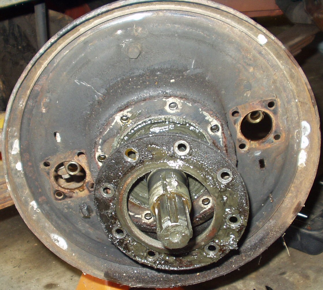
Axle Hub removed
Wipe the grease from inside the axle hub so you can see the lock washer. Use a screwdriver to bend the tab(s) up off the nut. Using a 50 mm socket (2" Deep well), a home made axle nut remover, a set of channel locks or a hammer and chisel (you should know better) remove the outer locking nut, lock washer, inner adjusting nut and claw washer. You can now slide the axle hub complete with wheel bearings off the spindle.
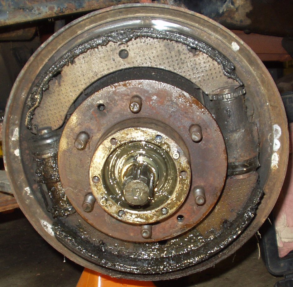
The true, early Cruiser expert will notice one thing very wrong with this picture and two minor things. I did not discover the major thing that was wrong until I started putting the wheel cylinders back on and was using the factory manual as a guide. Brief history of this vehicle. I am the 4th owner. I got the Cruiser from my brother who swears he NEVER did anything but put brake shoes on it. He complained from the day he got it that it would not stop properly. Said it had a bad pull to the right and just took way too much pedal pressure to stop it. So have you figured out what is wrong yet?
The Wheel cylinders are upside down! Before you claim that is not possible read on ...This is the drivers side. The wheel cylinders are for the passenger side! How do I know this? Well a Toyota wheel cylinder is stamped with a BIG R or L to let you know which side they belong on. Who ever had these off put them on the wrong side! This arrangement has the leading edge of the top shoe as the end that moves when you press the brake pedal and the trailing edge of the bottom shoe as the part that moves. According to the factory manual it's supposed to be the other way around ... My brother claims he never touched the wheel cylinders as long as he had it so it's a PO problem of course! The other two things are the shoe hold down pins and springs are missing and the brake shoe return springs are mounted wrong. The front spring should be behind the shoes and the rear spring should be in front of the shoes. It's no wonder this truck had terrible brakes!
Fig. 6 |
Fig. 7 |
Fig. 8 |
Fig. 9 |
If you are going to be replacing or rebuilding the wheel cylinders and /or replacing the shoes then now is the time to remove them. If you are just doing the knuckle rebuild then you can leave these parts in place on the backing plate and remove them as a unit. After removing the rubber brake hose skip to the Spindle removal section.
Ok now remove the brake shoe hold down springs and pins (if your truck has them!) then grasp the top shoe near the rear wheel cylinder and pull up enough to clear the adjustor slot it rests in. Do the same with the front of the top shoe. Now remove the shoes and springs. See Fig. 6.
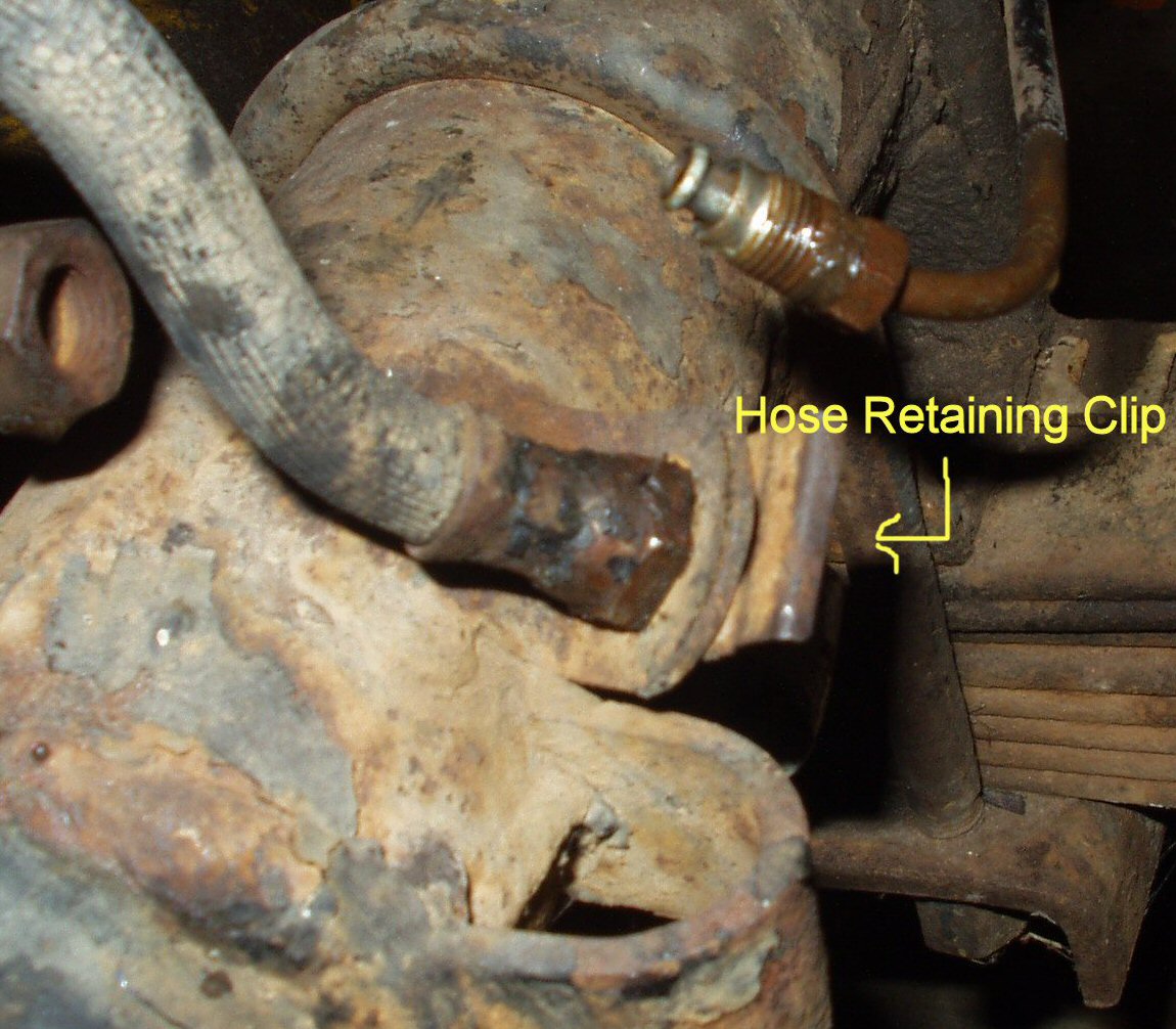
At this point you may want to empty the front master cylinder reservoir of brake fluid so it doesn't leak out on the floor like mine did! Or just have a small container handy to set under the disconnected hard line to catch the fluid. Using the 17 mm and 10 mm flare nut wrenches take the rubber brake hose loose from the hard line. Be VERY careful here! You do not want to round off the nut on the hard line! Once the lines are separated then remove the metal clip holding the hose in place. See Fig. 7-8. Mine was rusted in place and required a bit of 'persuasion'. Next use the 17 mm flare wrench to remove the banjo bolts connecting the wheel cylinders to the hard line manifold on the brake backing plate.
Using the 10 mm flare nut wrench remove the bleed screw from each wheel cylinder. Doing this now while the cylinders are firmly attached is much easier than trying to do it on the bench! Using a 12 mm socket remove the 4 bolts holding each wheel cylinder to the backing plate. It may be necessary to use a hammer and punch to knock the wheel cylinders loose from the backing plate. See Fig. 9. Using a 12 mm socket remove the brake hard line manifold retaining bolt.
Fig. 10 |
Fig. 11 |
Fig. 12 |
Removing Spindle/Brake Backing Plate
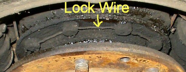
Using wire cutters cut the lock wire threaded through the spindle retaining bolts. See Fig. 10. Remove the pieces of wire. Using the 12 mm socket remove the 8 bolts in a crises cross pattern. Pry the oil retaining ring loose with the putty knife. See Fig. 11. Remove the backing plate. See Fig. 12. Use a rubber hammer to knock the spindle loose. See Fig. 13. You are half way there!
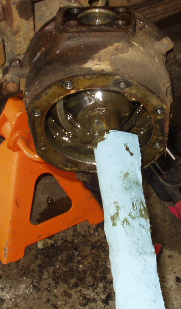
Fig. 13
Spindle off and Backing Plate Removed
Remove the cotter pins from the tie rods and loosen but do not remove the castle nuts. just like the cone washers described below YMMV on how effective the described technique will be in your case.
![]()
Fig. 14
Most auto parts stores like Advanced Auto Parts will let you borrow this tool with a deposit. It works by pressing the tie rod end out of the steering arm or what ever arm it is. If you use this tool then remove the castle nut entirely.
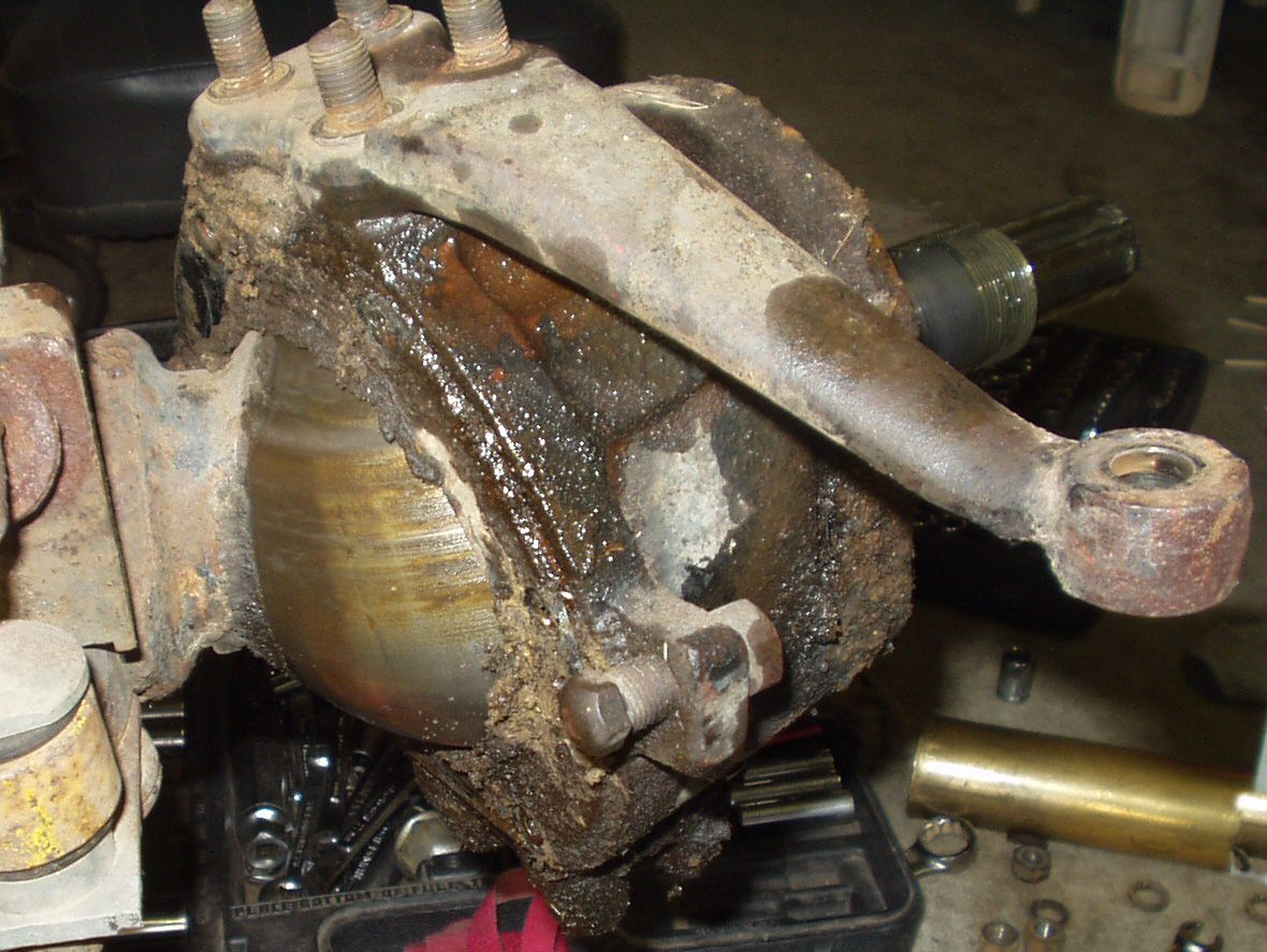
Fig. 15
Removing the Oil Seal Covers
See Fig. 15. Using a 10 mm socket remove the 8 bolts that hold the Oil Seal Covers to the back of the knuckle. Use the putty knife to remove the two half's. Pull the oil seal felt, rubber ring and split metal ring away from the ball and let hang.

Fig. 16
Cone Washer Removal
Ok now we have reached the hardest part of the disassembly: Removing the CONE WASHERS ... ** Update 5-18-2005 ** here is a commercial tool to help remove cone washers: Cone Washer Removal Tool.
Warning! YMMV on these removal techniques! First, using a 17 mm socket, remove the upper and lower stud nuts. Set these close by, you will need them later. Remove the lock washers. Use a wire brush to clean the area on top of the steering arm to expose the cone washers. Thread a stud nuts back on the studs finger tight. these will protect the threads when you miss. Place the punch against the side of one of the cone washers close to the split in the washer. Whack it HARD with the BFG. Repeat this for each stud. Now place the BIG end of the punch against the flat of a stud nut and repeat the whacking. Remove one of the stud nuts and thread it on top of one of the other nuts. Use a 17 mm wrench and a socket to tighten the two nuts against each other as hard as you can. Put the wrench on the bottom nut and try to turn the stud out. If you are lucky the stud will come right out! If you have a buddy helping have him whack with the punch while you turn. I was not lucky on the driver side and had to beat and beat. One technique that worked on one of the cone washers was to use a small chisel placed against the side and angled slightly upward to help loosen the cone washer. Just keep trying different things until you get them loose. Remember, if you mess up the threads on a stud you can get replacements cheaply. www.marlincrawler.com has them.
Whew! You now have the studs out and the cone washers removed! Have a beer! Enjoy life for a moment as we are about to begin the messy part of this disassembly ...
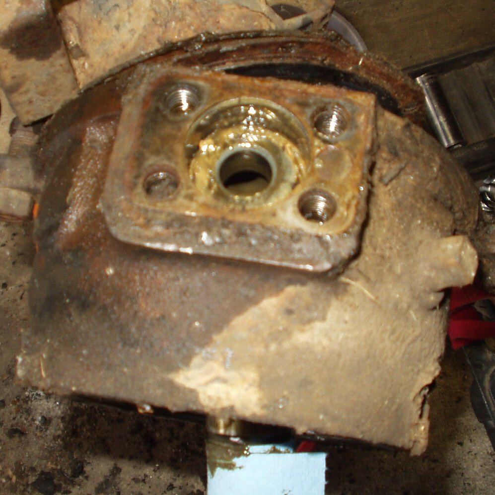
Fig. 17
Steering Arm Removed. See the Knuckle Bearing?
Remove the steering arm by rocking it back and forth. If it won't budge then use a soft faced hammer and tap the bearing stud from the inside until it pops free. Important! Remove ALL the shims and place them in a zip lock bag labeled as to which side they came from and whether they were on the top or bottom! Right now do it! It is critical that you not lose track of the location of these shims! They determine the pre-load on the knuckle bearings. When reassembling you want to put them back where they were as a staring point. Otherwise you will have to do the knuckle alignment which means buying an expensive tool.
Fig. 18 |
Fig. 19 |
Knuckle Housing Removed
Next grab the knuckle housing with both hands and lift straight up then tilt the top toward you. The knuckle will slide right off the ball. Ok you are almost done with the disassemble.
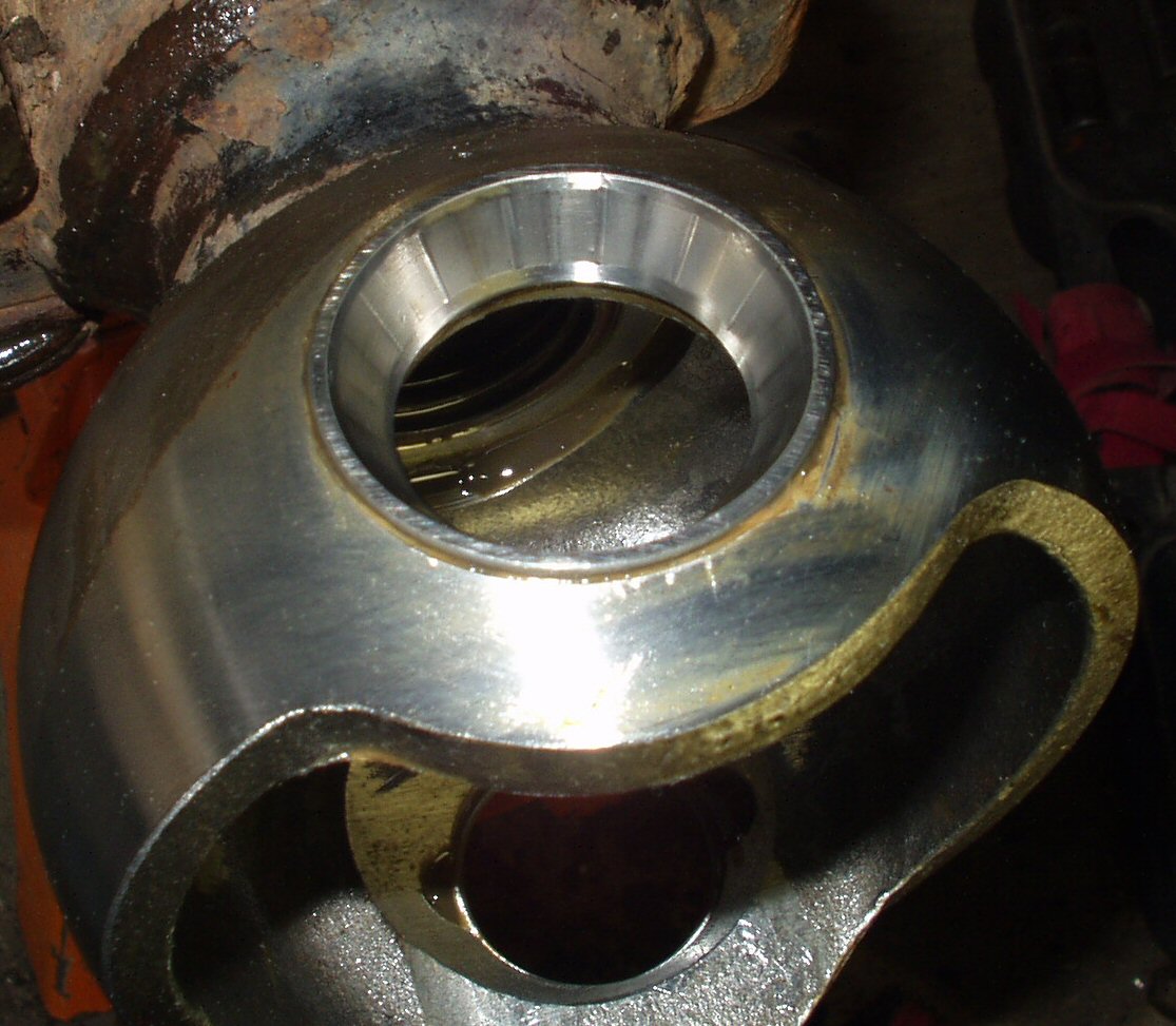
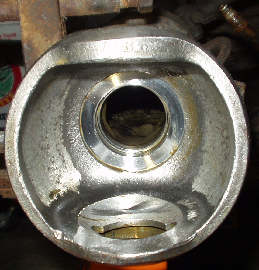
Fig. 20
Bearing removed, Axle out, grease wiped off
Clear out an area where you can safely lay the inner axle. It will be 4' long and slimy so make sure you have a place to put it before removing it. I used some old Christmas gift wrapping paper (don't tell the wife!) rolled out on the garage floor. I placed the axle on it, then rolled it up. Now I could place it anywhere without making a mess.
Grab the end of the axle and rotate it so that the flats of the Birfield joint are pointing up and down. Try to slide it out. If it won't come out then rotate the front drive shaft a bit and try again. Eventually it will line up and slide out.
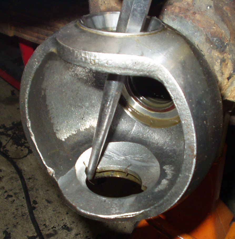
Remove the top bearing. Use a bunch of paper towels and wipe out all the grease from the knuckle inside and out till it looks like Fig. 20.
Carefully remove the metal split ring from the knuckle ball by tilting the top off the ring off the ball then the bottom. Save this ring as you will re-use it! Remove the rubber and felt rings and discard thm. New ones are in the rebuild kit.
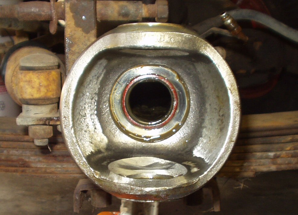
Fig. 21 Axle Seal |
Fig. 22 Removing Seal |
Fig. 23 Axle Seal Removed |
Now, using a seal puller remove the axle seal. See Fig. 21, 22 and 23.
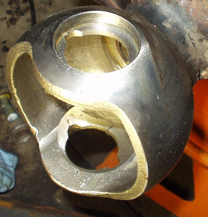
Fig. 24 Driving out race |
Fig. 25 Race Removed |
Last use a flat ended punch drive out the races top and bottom. Place the punch through the top bearing into one of the half moon cut outs in the housing. There is one on each side. See Fig. 24. Working back and forth drive the bottom race out. Repeat for the top race then do the other side. See Fig. 25 for pic of both races removed.
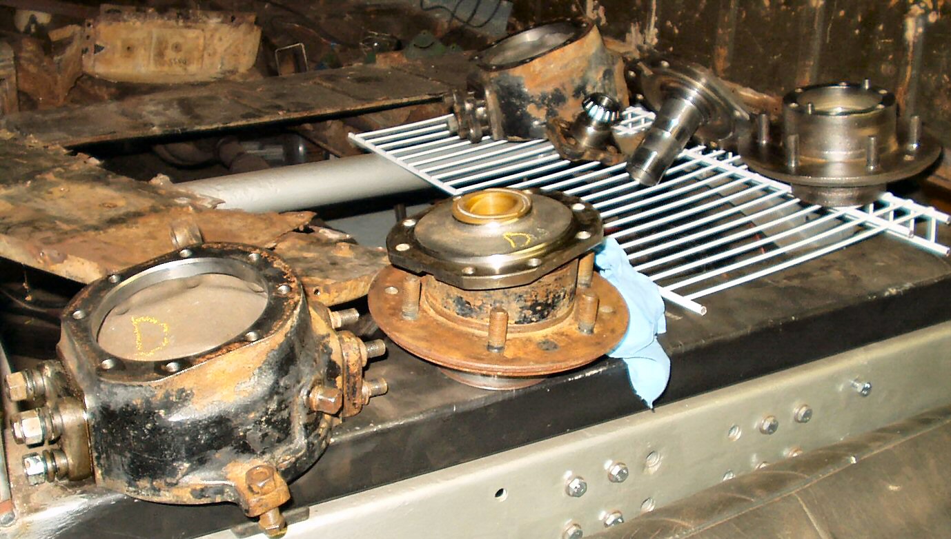
Fig. 26
Parts all degreased ready for Rust Removal
Well now the fun stuff is over. Thoroughly clean all the parts in a parts washer to remove all traces of grease and crud. If you plan on painting the parts, prep them by sand blasting, wire wheeling, or de-rusting using electrolyses. Prime and paint, or do what I did and powder coat.
Hosted by Global Software, Inc.
©1998 - 2023 Mark C. Baker Web Designer
Please: No part of this web site may be used without express permission... email mbaker@globalsoftware-inc.com for permission.